Project Asterales Proposal - NASA University Student Launch Initiative 19 September 2018
←
→
Page content transcription
If your browser does not render page correctly, please read the page content below
1845 Fairmount St.
                                Wichita, KS 67260-0044

Project Asterales
NASA University Student Launch Initiative

                Proposal

           19 September 2018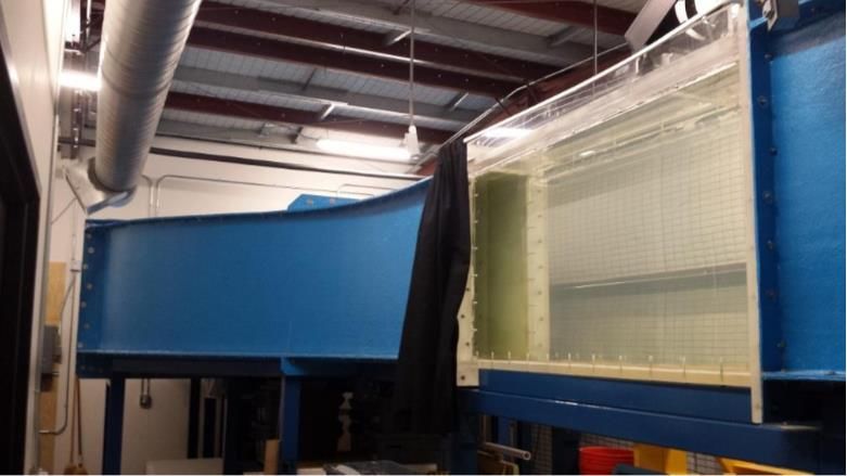
Table of Contents
List of Figures ............................................................................................................................................................ iii
List of Tables ...............................................................................................................................................................iv
Nomenclature ...............................................................................................................................................................v
1 General Information .................................................................................................................................................1
1.1 School Information and Project Title ...................................................................................................................1
1.2 Faculty Advisors and Mentors .............................................................................................................................1
1.3 Student Team Lead ..............................................................................................................................................1
1.4 Safety Officer ......................................................................................................................................................1
1.5 Organizational Structure ......................................................................................................................................1
1.5.1 Team Member Introductions ........................................................................................................................2
1.6 Tripoli Section and Launch Location ..................................................................................................................2
2 Team Mission Statement ..........................................................................................................................................3
3 Facilities and Equipment .........................................................................................................................................4
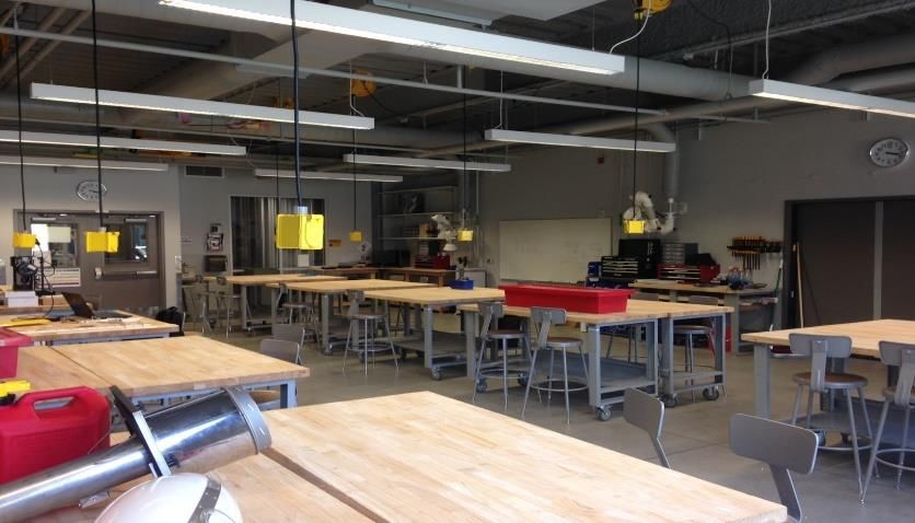
3.1 Aerospace Engineering Project and Prototyping Lab ..........................................................................................4
3.2 Project Innovation Hub ........................................................................................................................................4
3.2.1 Rapid Prototyping Lab ..................................................................................................................................5
3.3 Computational Hub ..............................................................................................................................................5
3.4 3’ by 4’ Low-Speed Wind Tunnel .......................................................................................................................5
3.5 Walter. H. Beech Wind Tunnel ...........................................................................................................................6
3.6 Water Tunnel .......................................................................................................................................................7
3.7 Aerospace Engineering Structures Lab ................................................................................................................7
3.8 Potential Propulsion Testing Apparatus...............................................................................................................7
3.9 Video Conferencing .............................................................................................................................................7
4 Safety .........................................................................................................................................................................8
4.1 Purpose ................................................................................................................................................................ 8
4.2 Regulatory Compliance .......................................................................................................................................8
4.2.1 NAR High Power Rocket Safety Code .........................................................................................................8
4.3 Wichita State Launch Safety Manual ................................................................................................................ 10
4.4 Material Safety .................................................................................................................................................. 10
4.5 Facility Safety .................................................................................................................................................... 10
4.6 Failure Modes and Effects Analysis .................................................................................................................. 10
4.7 Safety Personnel ................................................................................................................................................ 11
4.8 Signed Statement ............................................................................................................................................... 12
5 Technical Design ..................................................................................................................................................... 13
5.1 General Design Process ..................................................................................................................................... 13
5.2 Vehicle and Payload Overview.......................................................................................................................... 14
5.2.1 Launch Vehicle ........................................................................................................................................... 14
5.2.2 Active Drag................................................................................................................................................. 17
5.2.3 Payload ....................................................................................................................................................... 18
5.2.4 Payload Bay: Payload Retention, Orientation, and Deployment System .................................................... 20
5.2.5 Construction Techniques ............................................................................................................................ 21
5.3 Projected Altitude and Method of Calculation .................................................................................................. 21
5.4 Projected Recovery System Design ................................................................................................................... 21
5.5 Projected Motor Brand and Designation ............................................................................................................ 23
5.6 Requirements ..................................................................................................................................................... 24
5.7 Major Technical Challenges and Solutions ....................................................................................................... 24
5.8 Screening and Scoring ....................................................................................................................................... 24
6 Educational Engagement ....................................................................................................................................... 25
7 Project Plan ............................................................................................................................................................. 26
7.1 Development Schedule and Timeline ................................................................................................................ 26
7.2 Budget................................................................................................................................................................ 28
7.3 Funding Plan ...................................................................................................................................................... 30
i
7.4 Project and Team Sustainability ........................................................................................................................ 30
  7.5 Social Media and Website ................................................................................................................................. 30
  7.6 Requirements Verification Plan ......................................................................................................................... 31
8 Appendix A – FMEA Risk Evaluation Matrices .................................................................................................. 56
  8.1 Personnel Risk ................................................................................................................................................... 56
  8.2 Equipment Risk ................................................................................................................................................. 59
  8.3 Environmental Risk ........................................................................................................................................... 69

                                                                                    ii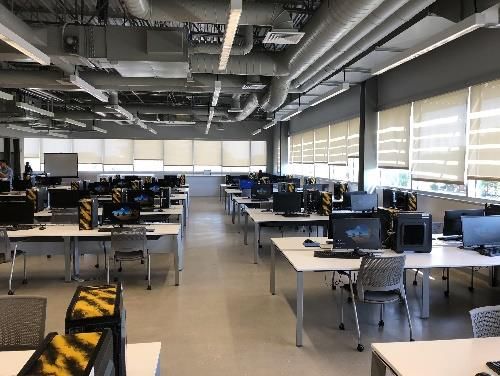
List of Figures

Wichita State Launch Team Organizational Structure ...................................................................................2
Project and Prototyping Lab ...........................................................................................................................4
Project Innovation Hub ..................................................................................................................................4
Rapid Prototyping Lab ...................................................................................................................................5
Computational Hub ........................................................................................................................................5
3’ by 4’ LSWT Overview...............................................................................................................................5
7’ by 10’ Pre-Section .....................................................................................................................................6
3’ by 4’ Main Test Section .............................................................................................................................6
Walter H. Beech Wind Tunnel Test Section ..................................................................................................6
 Flow Visualization Performed in Beech Wind Tunnel ................................................................................6
 Delta Wing Flow Visualization ....................................................................................................................7
 Water Tunnel Test Section ...........................................................................................................................7
 Material Test System....................................................................................................................................7
 Launch Vehicle Overview .......................................................................................................................... 14
 Launch Vehicle Layout .............................................................................................................................. 14
 Traditional Fin Can and Motor Mount ....................................................................................................... 15
 Full-Length Fin Can with Motor Retention................................................................................................ 15
 Short Fin Can ............................................................................................................................................. 15
 Motor Retention via Boattail ...................................................................................................................... 16
 Active Drag Flap Concept .......................................................................................................................... 17
 Active Drag Blades Stowed ....................................................................................................................... 17
 Active Drag Blades Deployed .................................................................................................................... 17
 Quadcopter with Folding Propeller Arms .................................................................................................. 18
 Quadcopter with Arms Folded ................................................................................................................... 19
 Two-Rotor UAV ........................................................................................................................................ 19
 Miniature Airship ....................................................................................................................................... 19
 Payload Sled with Stowed Quadcopter ...................................................................................................... 20
 Bearing Orientation System ....................................................................................................................... 21
 Drogue Deployment ................................................................................................................................... 22
 Main Parachute Deployment ...................................................................................................................... 22
 Project Phase Diagram ............................................................................................................................... 27

                                                                      iii
List of Tables

Minimum Distance Table ..............................................................................................................................................9
Hazard Probability ....................................................................................................................................................... 10
Hazard Severity ........................................................................................................................................................... 11
Risk Level/Assessment ................................................................................................................................................ 11
Launch Vehicle Specifications .................................................................................................................................... 16
Apogee Range due to Average Thrust Variation ......................................................................................................... 23
Major Technical Challenges and Proposed Solutions.................................................................................................. 24
Project Asterales Preliminary Schedule ....................................................................................................................... 26
Project Asterales Preliminary Budget .......................................................................................................................... 28
Proposed Requirement Verification Plan .................................................................................................................... 31
Personnel Risk Assessment ......................................................................................................................................... 56
Equipment Risk Assessment........................................................................................................................................ 59
Environmental Risk Assessment ................................................................................................................................. 69

                                                                                     iv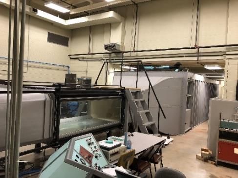
Nomenclature

AGL – Above Ground Level
APCP – Ammonium Perchlorate Composite Propellant
CAD – Computer Aided Design
CDR – Critical Design Review
CG – Center of Gravity
CP – Center of Pressure
FAA – Federal Aviation Administration
FEA – Future Excursion Area
FMEA – Failure Modes and Effects Analysis
FRR – Flight Readiness Review
LCO – Launch Control Officer
LSWT – Low-Speed Wind Tunnel
MSDS – Material Safety Data Sheet
MSFC – Marshall Space Flight Center
MTS – Material Test System
NFPA – National Fire and Prevention Agency
NAR – National Association of Rocketry
NASA – National Aeronautics and Space Administration
NIAR – National Institute of Aviation Research
PDR – Preliminary Design Review
PLAR – Post Launch Assessment Review
POD – Payload Retention, Orientation, and Deployment
PPE – Personal Protective Equipment
PID – Proportional-Integral-Derivative (with respect to controllers)
R&C’s – Requirements and Constraints
REM – Risk Evaluation Matrices
RK4 – Fourth Order Runge-Kutta Method
RSO – Range Safety Officer
SLI – Student Launch Initiative
TRA – Tripoli Rocketry Association
UAV – Unmanned Aerial Vehicle
WSL – Wichita State Launch
WSU – Wichita State University

                                                          v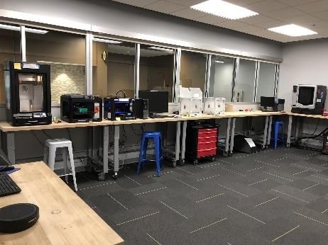
1 General Information

1.1 School Information and Project Title

University: Wichita State University
Team Name: Wichita State Launch
Project Title: Asterales
Launch Vehicle: M63
Payload Vehicle: M51/Little Blue Stem

1.2 Faculty Advisors and Mentors

Faculty Advisors
L. Scott Miller, Ph.D.
Wichita State University Aerospace Engineering Professor and Department Chair
Office: Wallace Hall Rm. 201
Email: scott.miller@wichita.edu
Phone: 316-978-6334

TRA Mentor
Steve Klausmeyer, Ph.D.
Sr. Engineering Specialist, Textron Aviation
Location: Wichita, KS
Email: smklausmeyer@txtav.com
Phone: 316-213-5587
Membership: TRA #8965
Certification: 3

1.3 Student Team Lead

Team Lead
Bryan Cline
2909 N. Oliver
Apt. 11-1122C
Wichita, KS 67220
Email: bccline24@gmail.com
Phone: 319-521-3543
Membership: TRA #18168

1.4 Safety Officer

Safety Officer
Michael Foster
2330 N. Oliver
Apt. 616
Wichita, KS 67220
Email: foster745@gmail.com
Phone: 913-982-6116

1.5 Organizational Structure

    The Wichita State Launch team is in its second year of existence and consists of four members of the Wichita State
University Aerospace Senior Design course. Acknowledging the small size of the team, the team has elected to assign
category leads functionally. All members will be active in each aspect of the project including research, design,
development, construction, and testing. The team will rely on independent work, collaboration, and the ability of each
team member to work within multiple disciplines. The organizational structure of the team is shown in Figure 1.

                                                          1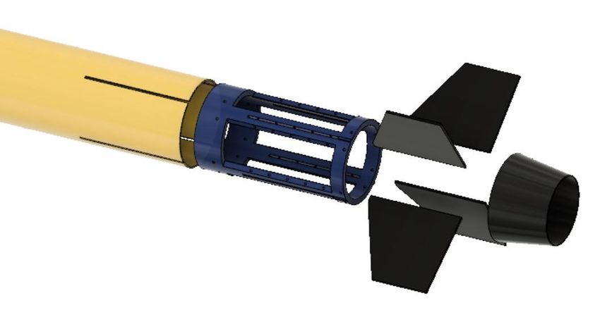
NASA

                                   TRA Mentor                  Faculty Advisors
                                  Dr. Klausmeyer                  Dr. Miller

    Payload and                Aerodynamics and               Stability Lead and               Propulsion and
  Structures Lead                 Team Lead                     Safety Officer                 Recovery Lead
      Jonathan                      Bryan                          Michael                         Skylar

                                    Wichita State Launch Team Organizational Structure

1.5.1 Team Member Introductions

    Jonathan was born and raised in Tampa, Florida. He studied physics at the University of North Georgia for several
years before transferring to Wichita State University in the Fall of 2017 to pursue a degree in aerospace engineering.
Jonathan has always had a strong interest in puzzles, problem solving, and figuring out how things work. He is excited
for the challenges and opportunities that the NASA Student Launch will present. For this project, Jonathan will be the
lead for structural analysis and payload design.
    Bryan is originally from Cedar Rapids, Iowa and studies saxophone performance and aerospace engineering at
Wichita State University. While rockets and saxophones seemingly are an unusual combination, he finds the two
disciplines to be complementary and fit his wide-ranging interests well. It is his long-term goal to work on full-scale
rocketry projects and is excited to get a taste of that through NASA Student Launch. Bryan will be acting as the team
lead and aerodynamics lead for this project.
    Skylar grew up in Pratt, Kansas and attended several colleges and universities before landing at Wichita State
University. He has explored several majors starting with sports administration before changing to mechanical
engineering, then mathematics, and finally aerospace engineering, with a brief stint as a dual major with physics.
Skylar decided on aerospace engineering because flight has always been fascinating to him and he has a particular
interest in outer space. Skylar will be the lead for propulsion, avionics, and recovery.
    Michael was born and raised in Leawood, Kansas, a suburb of Kansas City. After high school, he worked for a
few years doing jobs such as appliance repair, landscaping, and simple home remodeling before deciding to pursue an
engineering degree. Inspired by a lifelong interest in planes and rockets, Michael transferred to WSU to study
aerospace engineering in 2016 following two years of community college. Michael will serve as the team’s safety
officer, stability and fin analysis lead, and lead for coding and simulation.

1.6 Tripoli Section and Launch Location

KLOUDBusters Inc. (Tripoli Kansas #34)
c/o Science Education Center
2730 Boulevard Plaza
Wichita, KS 67211
Email: info@kloudbusters.org

Launch Location
37 deg. 10.070 min. N, 97 deg. 44.385 min. W
(Near Argonia, KS 67004)

                                                          2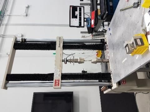
2 Team Mission Statement

    Wichita State Launch is committed to designing, building, and testing a reliable, safe, and reusable launch vehicle
and custom unmanned aerial vehicle (UAV) payload. The launch vehicle shall be designed to reach a target altitude
of 4,100 feet. An active drag system shall be implemented to improve apogee targeting. A dual-deployment recovery
system will be used to ensure a controlled landing of the launch vehicle. Upon landing of the launch vehicle, the UAV
will be deployed. The UAV will be capable of delivering a one cubic inch simulated navigational beacon to a
predetermined landing zone, known as a Future Excursion Area.
    The team is dedicated to safety, reliability, and validation. All design decisions shall be justified. All requirements
set forth by NASA, the FAA, Tripoli Rocketry Association/National Association of Rocketry, the NFPA, and other
authorities having jurisdiction shall be followed.
    Further, the Wichita State Launch team shall engage students and the community via outreach events intended to
inspire a love for science and engineering.

                                                            3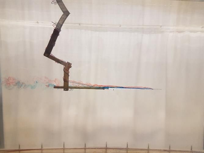
3 Facilities and Equipment
All facilities are staffed with relevant managers or assistants. Unless otherwise noted, each facility is available
upon scheduling a mutually agreeable time for the facility staff and the team.
3.1 Aerospace Engineering Project and Prototyping Lab
The Aerospace Engineering Project and Prototyping Lab is a 1,844 square foot workspace and will serve as one
of the main areas for vehicle construction and assembly. Available equipment includes a drill press, band saw, foam
cutter, spindle and disk sander, multiple CNC mills, laser cutters, and an assortment of hand and power tools. This
lab will also provide space for storage of the launch vehicle and its components. The Project and Prototyping Lab is
open Monday through Friday 9:00 a.m. to 9:00 p.m. and on the weekend by request.
Project and Prototyping Lab
3.2 Project Innovation Hub
Housed within the Experiential Engineering Building on Wichita State University’s Innovation Campus, the
Project Innovation Hub is a 4,114 square foot prototyping space consisting of fabrication, electronics, and 3D printing
and textiles labs. A wide range of equipment is available for use including woodworking tools, CNC routers, and a
manual mill. Project Innovation Hub hours are Monday through Friday from 9:00 a.m. to 10:00 p.m. and Saturday
from 11:00 a.m. to 10:00 p.m. The following list includes specific equipment that may be useful to the team:
Dewalt Compound Miter Saw, DW717
OMAX ProtoMAX Personal Abrasive Waterjet
Forest Scientific CNC Router, HS Router HS 4’ by 8’
Jet Belt Drive Bench Lathe, BD-920W
Langmuir Systems Crossfire Personal CNC Plasma Table
(coming soon)
Project Innovation Hub
43.2.1 Rapid Prototyping Lab
The Rapid Prototyping Lab will provide any 3D printing capabilities the team may require. The lab houses seven
3D printing stations and a 3D scanner. The available printers include the ability to manufacture components with ABS
plastic (up to 8” by 8” by 6”) and PLA plastic (up to 11.8” by 12” by 18”).
Rapid Prototyping Lab
3.3 Computational Hub
Located on the third floor of WSU’s Experiential Engineering Building, the Computational Hub includes several
large computer labs with a wide variety of software capabilities. The relevant software packages the team will have
access to include the Arduino IDE, Catia V5, Femap, Maple, MATLAB/Simulink, MSC Patran/Nastran, SolidWorks,
and ANSYS. The team will greatly benefit from the drafting, simulation, and finite element analysis capabilities
available in the computational hub.
Computational Hub
Additionally, the team has access to the Autodesk Student Suite through their student email accounts. The team
will also utilize OpenRocket and OpenVSP for early conceptual work.
3.4 3’ by 4’ Low-Speed Wind Tunnel
WSU’s 3’ by 4’ low-speed wind tunnel is an open loop tunnel which
includes a three-channel, truncated pyramidal external balance and
integrated data acquisition system. In the eight-foot-long test section,
airspeeds of up to 150 ft/s can be maintained (maximum dynamic
pressure is approximately 25 psf). Also available is the 7’ by 10’ pre-
section of the tunnel (Figure 7), which can provide air speeds of
approximately 20 ft/s. The 3’ by 4’ test section (Figure 8) may be useful
for collecting data on the subscale rocket model, while the 7’ by 10’ pre-
section may provide an ideal area to test the UAV flight under moderate
wind conditions.
3’ by 4’ LSWT Overview
57’ by 10’ Pre-Section 3’ by 4’ Main Test Section
3.5 Walter. H. Beech Wind Tunnel
The Walter H. Beech Wind Tunnel is a state-of-the-art, closed loop, low-speed wind tunnel with a 7’ by 10’ test
section spanning twelve feet in length. Operated by the National Institute of Aviation Research at Wichita State
University, the tunnel can provide air speeds of approximately 330 ft/s in the test section (maximum dynamic pressure
is approximately 125 psf). Force measurement data is recorded using a six-channel external balance. The team hopes
to utilize the Beech Wind Tunnel to carry out aerodynamic testing on the full-scale launch vehicle and to test the
characteristics of an active drag system.
Walter H. Beech Wind Tunnel Test Section
Flow Visualization Performed
in Beech Wind Tunnel1
1
“National Institute for Aviation Research - Walter H. Beech Wind Tunnel,” NIAR Available:
https://www.niar.wichita.edu/researchlabs/ad_overview.asp.
63.6 Water Tunnel
WSU’s Flow Visualization Lab consists of a water tunnel capable of providing a flow rate of up to 0.95 ft/s through
its 2’ by 3’ test section. The water tunnel has an integrated dye injection system and model attitude adjustment system
which allows for visualization of flow over installed aircraft or spacecraft models.
Water Tunnel Test Section2
Delta Wing Flow Visualization
3.7 Aerospace Engineering Structures Lab
The Aerospace Engineering Structures Lab, located in WSU’s Experiential Engineering Building, will allow the
team to determine or verify the material properties of any key components. Lab equipment includes several Material
Test System machines for tension and compression strength testing as well as optical deflection measurement systems.
Material Test System
3.8 Potential Propulsion Testing Apparatus
The Wichita State University Aerospace Engineering Department is currently considering the creation of a solid
rocket propellant motor test stand. Pending its completion, the team may utilize the test stand to verify the properties
of selected motors. The team’s mentor has a basic motor test stand that could be utilized if necessary.
3.9 Video Conferencing
The Wichita State University Media Resources Center will provide the necessary computer system, webcam, and
external microphone required for video conferencing with the review panel. A conference room will be reserved by
the team for the duration of the presentation.
2
Maneth, M., and Kliment, L., “Water Tunnel Operations Manual,” Sep. 2013.
74 Safety
4.1 Purpose
During all events and activities relating to Project Asterales, safety will be considered the highest priority. This
section describes the methods which the team will employ to ensure that all proper safety procedures and protocols
are followed during the project.
4.2 Regulatory Compliance
It is the intention of Wichita State Launch to ensure that all project activities undertaken by team members or
others involved with Project Asterales comply with all local, state, and federal regulations. Each team member has
reviewed and understands the laws and regulations that will apply to the project including Federal Aviation Regulation
14 CFR Part 101, Subpart C: Amateur Rockets, Code of Federal Regulations 27 Part 55: Commerce in Explosives,
and National Fire Protection Agency 1127 “Code for High Power Rocketry.”
4.2.1 NAR High Power Rocket Safety Code3
In addition to following all local, state, and federal regulations, the team will adopt and abide the safety
procedures and guidelines of the National Association of Rocketry. The relevant set of NAR guidelines for Project
Asterales is the High Power Rocket Safety Code, listed below:
1. Certification. I will only fly high power rockets or possess high power rocket motors that are within the scope
of my user certification and required licensing.
2. Materials. I will use only lightweight materials such as paper, wood, rubber, plastic, fiberglass, or when
necessary ductile metal, for the construction of my rocket.
3. Motors. I will use only certified, commercially made rocket motors, and will not tamper with these motors or
use them for any purposes except those recommended by the manufacturer. I will not allow smoking, open
flames, nor heat sources within 25 feet of these motors.
4. Ignition System. I will launch my rockets with an electrical launch system, and with electrical motor igniters
that are installed in the motor only after my rocket is at the launch pad or in a designated prepping area. My
launch system will have a safety interlock that is in series with the launch switch that is not installed until my
rocket is ready for launch, and will use a launch switch that returns to the “off” position when released. The
function of onboard energetics and firing circuits will be inhibited except when my rocket is in the launching
position.
5. Misfires. If my rocket does not launch when I press the button of my electrical launch system, I will remove the
launcher’s safety interlock or disconnect its battery, and will wait 60 seconds after the last launch attempt before
allowing anyone to approach the rocket.
6. Launch Safety. I will use a 5-second countdown before launch. I will ensure that a means is available to warn
participants and spectators in the event of a problem. I will ensure that no person is closer to the launch pad than
allowed by the accompanying Minimum Distance Table. When arming onboard energetics and firing circuits I
will ensure that no person is at the pad except safety personnel and those required for arming and disarming
operations. I will check the stability of my rocket before flight and will not fly it if it cannot be determined to be
stable. When conducting a simultaneous launch of more than one high power rocket I will observe the additional
requirements of NFPA 1127.
3
“High Power Rocket Safety Code,” National Association of Rocketry Available: http://www.nar.org/safety-information/high-
power-rocket-safety-code/.
87. Launcher. I will launch my rocket from a stable device that provides rigid guidance until the rocket has attained
a speed that ensures a stable flight, and that is pointed to within 20 degrees of vertical. If the wind speed exceeds
5 miles per hour I will use a launcher length that permits the rocket to attain a safe velocity before separation
from the launcher. I will use a blast deflector to prevent the motor’s exhaust from hitting the ground. I will ensure
that dry grass is cleared around each launch pad in accordance with the accompanying Minimum Distance table,
and will increase this distance by a factor of 1.5 and clear that area of all combustible material if the rocket motor
being launched uses titanium sponge in the propellant.
8. Size. My rocket will not contain any combination of motors that total more than 40,960 N-sec (9208 pound-
seconds) of total impulse. My rocket will not weigh more at liftoff than one-third of the certified average thrust
of the high power rocket motor(s) intended to be ignited at launch.
9. Flight Safety. I will not launch my rocket at targets, into clouds, near airplanes, nor on trajectories that take it
directly over the heads of spectators or beyond the boundaries of the launch site, and will not put any flammable
or explosive payload in my rocket. I will not launch my rockets if wind speeds exceed 20 miles per hour. I will
comply with Federal Aviation Administration airspace regulations when flying, and will ensure that my rocket
will not exceed any applicable altitude limit in effect at that launch site.
10. Launch Site. I will launch my rocket outdoors, in an open area where trees, power lines, occupied buildings,
and persons not involved in the launch do not present a hazard, and that is at least as large on its smallest
dimension as one-half of the maximum altitude to which rockets are allowed to be flown at that site or 1500 feet,
whichever is greater, or 1000 feet for rockets with a combined total impulse of less than 160 N-sec, a total liftoff
weight of less than 1500 grams, and a maximum expected altitude of less than 610 meters (2000 feet).
11. Launcher Location. My launcher will be 1500 feet from any occupied building or from any public highway on
which traffic flow exceeds 10 vehicles per hour, not including traffic flow related to the launch. It will also be
no closer than the appropriate Minimum Personnel Distance from the accompanying table from any boundary
of the launch site.
12. Recovery System. I will use a recovery system such as a parachute in my rocket so that all parts of my rocket
return safely and undamaged and can be flown again, and I will use only flame-resistant or fireproof recovery
system wadding in my rocket.
13. Recovery Safety. I will not attempt to recover my rocket from power lines, tall trees, or other dangerous places,
fly it under conditions where it is likely to recover in spectator areas or outside the launch site, nor attempt to
catch it as it approaches the ground.
All launch procedures will be in agreement with the following table included in the NAR High Power Rocket
Safety Code:
Minimum Distance Table
High Power Min. Diameter of Min. Personnel Min. Personnel Distance
Total Impulse (N∙s)
Motor Type Cleared Area (ft.) Distance (ft.) (complex rocket) (ft.)
0-320.00 H or smaller 50 100 200
320.01-640.00 I 50 100 200
640.01-1,280.00 J 50 100 200
1,280.1-2,560.00 K 75 200 300
2,560.01-5,120.00 L 100 300 500
5,120.01-10,240.00 M 125 500 1,000
10,240.01-20,480.00 N 125 1,000 1,500
20,480.01-40,960.00 O 125 1,500 2,000
94.3 Wichita State Launch Safety Manual
In an effort to promote and facilitate the practice of safe procedures and precautions during Project Asterales as
well as future NASA USLI projects undertaken by students at Wichita State University, the team will produce and
maintain an official safety manual. The WSL Safety Manual will include material safety data sheets for all relevant
materials, proper safety procedures for handling and storing such materials, proper building procedures and
techniques, required personal protective equipment, facility and tool specific rules and procedures, as well as response
procedures in the case of a safety emergency. Also included in the manual will be launch checklists and procedures.
Safety briefings reminding the team of launch-day rules and procedures will be conducted by the safety officer prior
to all launches. The WSL Safety Manual will be updated as needed throughout the project to include any newly
relevant materials, facilities, or situations. All team members, and any others involved in project activities, will have
access to (electronically and hard-copy) the WSL Safety Manual and are expected to review relevant information
before starting any of the included activities.
4.4 Material Safety
In the process of building, storing, transporting, and launching a high power rocket, team members of Project
Asterales, including the team mentor, will be in close proximity to or in contact with a variety of hazardous
materials. To ensure that these materials are handled and stored in the safest possible way, procedures for the handling
of materials and material safety data sheets (MSDS) for all materials involved will be available in the Wichita State
Launch Safety Manual. Anyone taking part in a project related activity involving said materials must review, in full,
the relevant Safety Manual instructions and MSDS before starting the activity. Proper personal protection equipment
for each activity shall be clearly identified within the WSL Safety Manual.
4.5 Facility Safety
In addition to following all team rules included in the WSL Safety Manual, the team will adopt all facility specific
safety rules. As students at Wichita State University, the team will have access to a number of lab spaces housing a
wide range of tools and machinery. These tools and machinery often require specific rules and safety
guidelines. Facility and tool specific rules and procedures will be included in the WSL Safety Manual, and all such
relevant rules and procedures will be reviewed and understood by team members before starting any building activity.
4.6 Failure Modes and Effects Analysis
As part of Wichita State Launch’s commitment to maintaining an exceptional level of safety throughout the
duration of Project Asterales, a failure mode and effects analysis (FMEA) will be conducted for all project-related
systems and safety hazards. The purpose of this analysis is to provide the team with a systematic method for evaluating
risk and determining which risk areas will require the closest attention.
Failure of systems and safety hazards will be evaluated to determine values based on their probability of occurrence
and the severity of the danger they represent. The probability of occurrence (P) and the severity (S) will be used to
calculate the Risk Level (R) where R = P+S.
The probability of occurrence will be defined as the likelihood of a failure event taking into account the probability
that an issue exists as well as the probability that the issue will be detected by the team prior to launch or testing. Each
failure scenario probability will be evaluated according to the following table:
Hazard Probability
Probability Designation (Value) Probability (%)
Extremely likely to occur (1) Greater than 65
Likely to occur (2) 46 - 65
Moderate chance to occur (3) 26 - 45
Unlikely to occur (4) 6 - 25
Extremely unlikely to occur (5) 0-5
10The severity of each failure scenario will be evaluated based on the level of danger it presents to the safety of
nearby people and property according to the following table:
Hazard Severity4
Severity Designation Description
(Value) Personnel Equipment/Facility Environmental
Loss of life or a Irreversible severe
Loss of facility, systems
Catastrophic (1) permanent-disabling environmental damage that
or associated hardware.
injury. violates law and regulation.
Severe injury or Major damage to Reversible environmental
Critical (2) occupational-related facilities, systems, or damage causing a violation of
illness. equipment. law or regulation.
Mitigatable environmental
Minor injury or Minor damage to damage without violation of
Marginal (3) occupational-related facilities, systems, or law or regulation where
illness. equipment. restoration activities can be
accomplished.
First-aid injury or Minimal damage to Minimal environmental
Negligible (4) occupational-related facility, systems, or damage not violating law or
illness. equipment. regulation.
Each Risk Level value will correspond to a risk assessment according to the following table:
Risk Level/Assessment
Probability / Severity Catastrophic (1) Critical (2) Marginal (3) Negligible (4)
Extremely likely (1) (2) - Unacceptable (3) - Unacceptable (4) - High (5) - Moderate
Likely (2) (3) - Unacceptable (4) - High (5) - Moderate (6) - Moderate
Moderate (3) (4) - High (5) - Moderate (6) - Moderate (7) - Low
Unlikely (4) (5) - Moderate (6) - Moderate (7) - Low (8) - Minimal
Extremely unlikely (5) (6) - Moderate (7) - Low (8) - Minimal (9) - Minimal
Based on the risk assessment for each failure scenario, an appropriate mitigation will be determined and enacted
by the team. This process will be vital for maximizing safety, minimizing risk, and contributing to the overall success
of the team.
All of the information (P, S, R, risk assessment, and mitigations) for particular failure modes and scenarios will be
collected in risk evaluation matrices (REM). Please see Appendix A – FMEA Risk Evaluation Matrices.
4.7 Safety Personnel
Safety Officer
Michael will serve as the Safety Officer for Project Asterales. In this role, his responsibilities include but are not
limited to the following:
1. Managing the creation and maintenance of the WSL Safety Manual
2. Supervising launch day procedures and activities
3. Ensuring team members are following all team safety rules and procedures
4
2018 NASA Student Launch Handbook
114. Ensuring team members and activities are in compliance with all local, state and federal regulations
Michael is determined to help the team achieve its goal of maintaining the highest level of safety possible for
everyone involved in the project.
NAR/TRA Mentor
The team’s mentor, Dr. Steve Klausmeyer has many years of experience working as an engineer in the aerospace
industry and is a long-time model rocket hobbyist. He holds Level 3 Certification with Tripoli Rocketry Association
and has had many successful launches in the Level 3 impulse class. This certification allows him to purchase, handle,
store, and transport any rocket motor within the high power rocket designation, including the ones to be used during
this competition. Dr. Klausmeyer will also be responsible for handling of all necessary black power. All energetic
materials will be stored in Dr. Klausmeyer’s fire safe.
4.8 Signed Statement
The team members of Wichita State Launch participating in Project Asterales as part of the 2018-2019 NASA
University Student Launch Initiative will understand and abide by the following safety regulations:
1. Range safety inspections will be conducted on each rocket before it is flown. Each team shall comply with
the determination of the safety inspection or may be removed from the program.
2. The Range Safety Officer has the final say on all rocket safety issues. Therefore, the Range Safety Officer
has the right to deny the launch of any rocket for safety reasons.
3. The team mentor is ultimately responsible for the safe flight and recovery of the team’s rocket. Therefore, a
team will not fly a rocket until the mentor has reviewed the design, examined the build and is satisfied the
rocket meets established amateur rocketry design and safety guidelines.
4. Any team that does not comply with the safety requirements will not be allowed to launch their rocket.
The following signatures represent acceptance of all relevant safety regulations and procedures.
125 Technical Design
5.1 General Design Process
Project Asterales has adopted the following general design process which closely resembles industry design
practices:
1. Study the mission
2. Study the existing and potential competition
3. Develop initial non-technical Requirements and Constraints (R&C’s)
4. Generate concepts
5. Screen and score concepts – commit to a concept
6. Develop and expand technical R&C’s
7. Complete conceptual design
8. Complete preliminary design
9. Complete detailed design
10. Prototype and build
11. Test
12. Demonstrate
The initial steps undertaken by the team included a detailed study of the 2018 NASA Student Launch competition
as well as a thorough review of the technical documentation submitted by competing teams. The purpose of this
process was for the team to familiarize itself with the considerations necessary for participation in this competition as
well to identify the characteristics of successful teams and projects. This allowed the team to begin to compile an
initial list of key non-technical requirements for the project which include:
Vehicle size must facilitate ease of work
Vehicle must be able to be prepared for launch within two hours
Vehicle must be easily analyzed using traditional methods
Ease of transport
Vehicle must be recovered in a reusable state
Recovery systems must be redundant
Payload must be able to take off from rough terrain
Launch vehicle and payload must comply with all relevant local, state, and federal regulations
Upon the release of the 2019 NASA Student Launch Handbook, the new mission requirements and constraints
were studied in detail. Key technical requirements set by NASA for the selected mission include:
Selected target apogee must be between 4,000 feet and 5,500 feet
Launch vehicle must remain subsonic
Descent time must be under 90 seconds
Impact energy must be under 75 ft∙lb
Must use commercially available rocket motors (maximum total impulse = 1,150 lb∙s)
Rail exit stability margin must be at least 2.0
Payload must be able to carry a 1” x 1” x 1” simulated navigational beacon
Payload must be autonomously oriented and deployed upon landing of rocket
Additionally, the team has noted that uncertainties in launch conditions and variations in motor performance result
in the need for the development of an active drag system to reliably target a specific apogee.
Following the identification of the key technical requirements, a MATLAB 5 simulation of the launch vehicle’s
flight profile using fundamental physics principles was created. The simulation has allowed the team to take the first
steps to identify launch vehicle configurations which satisfy all mandated technical requirements. These initial steps
5 “MATLAB R2018a,” MathWorks.
13included determining a viable launch vehicle weight as well as viable sizes for the drogue and main parachutes. Data
from the team-developed simulation was compared with data from OpenRocket 6.
Knowing some of the key sizing boundaries, the team proceeded to generate concepts and potential configurations
for the launch vehicle and payload. This proposal is designed to document the conceptual and notional designs being
considered and analyzed by the team. A screening and scoring process will be undertaken to further evaluate and
refine said concepts. Upon completing the screening and scoring process, a selection of the final concepts will be
made for further development.
5.2 Vehicle and Payload Overview
5.2.1 Launch Vehicle
Team-imposed design criteria for the launch vehicle include minimizing weight and use of adhesives, facilitating
construction, and allowing for accurate analysis. While only one configuration is discussed in detail here, others,
including larger diameters and configurations with a payload fairing, are being investigated. Several options are being
considered for many of the subsystems and are described in the following sections.
The current proposed launch vehicle configuration, shown in Figure 14, is 4.5 inches in diameter and constructed
primarily of fiberglass. While identification of maximum structural loads and analysis has not yet been performed,
fiberglass is being considered on the recommendation of the team’s mentor and as a response to the 2017-2018 Wichita
State Launch team having persistent problems with zippering. While fiberglass is resistant to zippering, it weighs more
than some other options. The diameter has tentatively been selected to address weight concerns and allow for a
reasonably sized payload. The material selection is subject to change due to the team goal of minimizing weight and
the ongoing processes of sizing, payload design, and structural analysis.
Launch Vehicle Overview
Due to the small team size, an effort will be made to use commercially available components when possible. A
4:1 fiberglass tangent ogive nose cone has been selected due to its availability.
The current lay out of the proposed launch vehicle will consist of three sections and thus two points of separation
(Figure 15). This layout has been selected to minimize weight, facilitate payload deployment, and meet all vehicle
requirements.
Launch Vehicle Layout
The team has currently elected to utilize a cruciform fin configuration. This allows the fins to extend a shorter
distance from the airframe than if a three-fin configuration was used in order to achieve the same level of stability.
Cruciform fin configurations are also commonly used on sounding rockets and missiles and thus may be easily
compared to published information. The current fin shape has been optimized using OpenRocket, but study of clipped
delta, trapezoidal, and swept trapezoidal fins will be completed upon the maturing of the team-developed simulation
to better model drag over those shapes.
6 “OpenRocket v15.04,” OpenRocket
14In an effort to minimize reliance on adhesives during construction, the team is considering several options for the
aft assembly. One proposed aft assembly, shown in Figure 16, would involve traditional centering rings and bulkheads
being screwed into the airframe. A removable fin can system is also under consideration. In one such configuration,
the fin can would also serve as the motor mount (Figure 17). In this design, the fin can spans the entire length of the
motor casing and the fins are mounted to the fin can with screws before being slid into the body. The fin can is then
screwed into the airframe.
Traditional Fin Can and Motor Mount
Full-Length Fin Can with Motor Retention
A variant of this design, depicted in Figure 18, would include a shorter fin can designed only to hold the fins.
Traditional centering rings and bulkheads would also be required. 3D printed ABS is under consideration for both fin
can assemblies. A removable fin can allows for easy repair in case of fin failure and the ability to rapidly test fin
shapes in wind tunnel testing and test flights.
Short Fin Can
15As a means of reducing base drag by minimizing flow separation aft of the motor, the launch vehicle will be
equipped with a boattail. The boattail will also provide active motor retention. Attachment of the boattail depends on
the selected means of mounting the fins and housing the motor casing. The removable fin can may include a threaded
extension that would allow the boattail to be attached to the bottom of the fin can as shown in Figure 19. The boattail
will likely be made of lightweight aluminum so as to be able to withstand the high temperatures that result from motor
burn.
Motor Retention via Boattail
Proposed launch vehicle specifications are summarized below.
Launch Vehicle Specifications
Launch Weight 20.2 lb
Dry Weight 17 lb
Total Length 79 in.
Fore (Payload) Section Length 12 in.
Mid Section Length 18 in.
Aft Section Length 28 in.
Body Diameter 4.5 in.
Nose Cone Geometry 4:1 Ogive
Fin Configuration Cruciform
Body Tube Material Fiberglass
Motor Designation AeroTech K1103X-14A
CG (from nose) 45.7 in.
CP (from nose) 55.4 in.
Rail Exit Stability Margin 2.16 cal.
Rail Exit Velocity 87 ft/s
Drogue Parachute 15 in. Classic Elliptical (Fruity Chutes)
Main Parachute 84 in. Iris Ultra Standard (Fruity Chutes)
Deployment Method Black Powder
Payload UAV
Apogee (without active drag system) 4,325 feet
Maximum Mach Number 0.54
165.2.2 Active Drag
The commercially available rocket motors that are required for use during the competition are permitted to vary
from the stated performance values given by the manufacturer regarding total impulse and average thrust.
Additionally, specific launch day atmospheric conditions are unknown. Therefore, as noted in Section 5.1, the team
has determined that the employment of an active drag system is necessary to achieve a specific apogee.
There are several possible methods for actively varying the drag force experienced by the launch vehicle. The
team is investigating two general methods of varying the exterior profile of the launch vehicle. The first involves an
angled deployment of hinged flaps from the sides of the vehicle in a similar manner to “speed” or “diving” brakes on
some aircraft, as seen in Figure 20. The second method involves rotation of blades from the interior of the launch
vehicle which extend perpendicularly to the flow (Figure 21, Figure 22).
Active Drag Flap Concept
Active Drag Blades Stowed Active Drag Blades Deployed
17Further analysis in terms of required drag and structural loads will be undertaken to select the most promising
concept. Other concept selection concerns include feasibility of construction, reliability, and flow separation. Flow
separation can often be mitigated via a small gap between the airframe and the flap 7 or by perforating the plate8. To
minimize the disturbance of flow over the fins (and thus minimize effects on stability), both designs will make use of
four drag-inducing components (four flaps or blades) which will be deployed at 45 degree offsets from the fins.
The active drag system will likely utilize a PID feedback control system to command the position of the flaps or
blades. In order to determine the required position of the flaps or blades, the system will need to account for the launch
vehicle’s current acceleration, velocity, and altitude. Data filters will be considered to reduce signal noise but may
slow the processing speed of the control system.
5.2.3 Payload
The team carefully considered both payload options for the 2019 challenge. The competitive analysis of last year’s
competition and determined the most successful rovers were quite large in size and weighed upwards of four pounds.
Upon realizing minimizing weight is a key goal to success and meeting the team-imposed requirements, the team has
selected the unmanned aerial vehicle payload option due to the belief that the overall weight of the payload section
(including the UAV) will weigh less than a rover.
Several possible UAV designs are being considered. Key drivers in selecting a payload design involve size, weight,
ease of construction, and reliability of the control scheme.
Multiple quadcopter configurations are being investigated due to their ease of construction, stability, and control.
One potential option is a small quadcopter that could fit within the payload bay in a ready-to-fly configuration. This,
however, will likely result in a very small vehicle which may not handle the potential need to fly a long distance to
the Future Excursion Area. In response, several folding quadcopters are also being considered (Figure 23, Figure 24).
These would permit the team to create a larger UAV and potentially improve long distance flight characteristics.
Quadcopters ability to hover would also be beneficial in terms of accurately releasing the simulated navigational
beacon.9
Quadcopter with Folding Propeller Arms
7
Fuchs, D., “Wind-Tunnel Investigations of Diving Brakes,” NASA Technical Reports Server, Nov. 1942.
8
de Bray, B. G., “Low Speed Wind Tunnel Tests on Perforated Square Flat Plates Normal to the Airstream,” A.R.C. Technical
Report, 1957.
9
Lozano, R., Unmanned Aerial Vehicles Embedded Control, John Wiley & Sons, 2010.
18You can also read