WALK-IN VAN CHASSIS - Maintenance Manual - FCCC Van
←
→
Page content transcription
If your browser does not render page correctly, please read the page content below

WALK-IN VAN
            CHASSIS

                Maintenance Manual
STI-471-6
A24-01451-000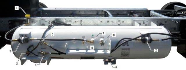
WALK-IN VAN CHASSIS MAINTENANCE MANUAL

Models: MT45
        MT45        G
        MT45        HEV
        MT55
        MT55        G
        MT55        HEV
        MT55        HHV

STI-471-6 (11/15)
                                                 Published by
                            Daimler Trucks North America LLC
                                        4747 N. Channel Ave.
                                          Portland, OR 97217
                                             Printed in U.S.A.
Foreword
Scheduled maintenance provides a key element for safe operation of your vehicle. A proper
maintenance program also helps to minimize downtime and to safeguard warranties. This mainte-
nance manual provides information necessary for years of safe, reliable, and cost-efficient vehicle
operation.
IMPORTANT: The maintenance operations in this manual are not all-inclusive. Also refer to
other component and body manufacturers’ instructions for specific inspection and mainte-
nance instructions.
Perform daily pretrip inspection and maintenance as outlined in the vehicle operator’s manual.
Perform the operations in this maintenance manual at scheduled intervals based upon distance
traveled or months of operation. Your authorized servicing dealer has the qualified technicians and
equipment to perform this maintenance for you. Your dealership can also set up a scheduled
maintenance program tailored specifically to your needs. Optionally, your dealership can assist you in
learning how to perform the maintenance procedures in this manual.
IMPORTANT: Descriptions and specifications in this manual were in effect at the time of
printing. Freightliner Custom Chassis Corporation (FCCC) reserves the right to discontinue
models and to change specifications or design at any time without notice and without
incurring obligation. Descriptions and specifications contained in this publication provide no
warranty, expressed or implied, and are subject to revision and editions without notice.
Refer to www.Daimler-TrucksNorthAmerica.com and www.FreightlinerChassis.com for more
information, or contact Daimler Trucks North America LLC at the address below.
Environmental Concerns and Recommendations
Whenever you see instructions in this manual to discard materials, you should attempt to reclaim and
recycle them. To preserve our environment, follow appropriate environmental rules and regulations
when disposing of materials.
NOTICE: Parts Replacement Considerations
Do not replace suspension, axle, or steering parts (such as springs, wheels, hubs, and steering gears)
with used parts. Used parts may have been subjected to collisions or improper use and have
undetected structural damage.
© 1997–2016 Daimler Trucks North America LLC
All rights reserved. No part of this publication, in whole or in part, may be translated, reproduced,
stored in a retrieval system, or transmitted in any form by any means, electronic, mechanical,
photocopying, recording, or otherwise, without the prior written permission of Daimler Trucks North
America LLC. Daimler Trucks North America LLC is a Daimler company.
Daimler Trucks North America LLC
Service Systems and Documentation (CVI-SSD)
P.O. Box 3849
Portland, OR 97208–3849Introduction
Descriptions of Service Publications
Daimler Trucks North America LLC distributes the following major service publications in paper and electronic
(via ServicePro®) formats.
Workshop/Service Workshop/service manuals contain service and repair information for all vehicle
Manual systems and components, except for major components such as engines, trans-
missions, and rear axles. Each workshop/service manual section is divided into
subjects that can include general information, principles of operation, removal,
disassembly, assembly, installation, and specifications.
Maintenance Manual Maintenance manuals contain routine maintenance procedures and intervals for
vehicle components and systems. They have information such as lubrication
procedures and tables, fluid replacement procedures, fluid capacities, specifica-
tions, and procedures for adjustments and for checking the tightness of fasten-
ers. Maintenance manuals do not contain detailed repair or service information.
Driver’s/Operator’s Driver’s/operator’s manuals contain information needed to enhance the driver’s
Manual understanding of how to operate and care for the vehicle and its components.
Each manual contains a chapter that covers pre-trip and post-trip inspections,
and daily, weekly, and monthly maintenance of vehicle components.
Driver’s/operator’s manuals do not contain detailed repair or service information.
Service Bulletins Service bulletins provide the latest service tips, field repairs, product improve-
ments, and related information. Some service bulletins are updates to informa-
tion in the workshop/service manual. These bulletins take precedence over
workshop/service manual information, until the latter is updated; at that time, the
bulletin is usually canceled. The service bulletins manual is available only to
dealers. When doing service work on a vehicle system or part, check for a valid
service bulletin for the latest information on the subject.
IMPORTANT: Before using a particular service bulletin, check the current
service bulletin validity list to be sure the bulletin is valid.
Parts Technical Bulletins Parts technical bulletins provide information on parts. These bulletins contain
lists of parts and BOMs needed to do replacement and upgrade procedures.
Web-based repair, service, and parts documentation can be accessed using the following applications on the
AccessFreightliner.com website.
ServicePro ServicePro® provides Web-based access to the most up-to-date versions of the
publications listed above. In addition, the Service Solutions feature provides di-
agnostic assistance with Symptoms Search, by connecting to a large knowledge
base gathered from technicians and service personnel. Search results for both
documents and service solutions can be narrowed by initially entering vehicle
identification data.
PartsPro PartsPro® is an electronic parts catalog system, showing the specified vehicle’s
build record.
EZWiring EZWiring™ makes Freightliner Custom Chassis Corporation, Freightliner, Ster-
ling, Western Star, and Thomas Built Buses products’ wiring drawings and float-
ing pin lists available online for viewing and printing. EZWiring can also be ac-
cessed from within PartsPro.
Walk-In Van Chassis Maintenance Manual, January 2011 I–1Introduction
Descriptions of Service Publications
Warranty-related service information available on the AccessFreightliner.com website includes the following
documentation.
Recall Campaigns Recall campaigns cover situations that involve service work or replacement of
parts in connection with a recall notice. These campaigns pertain to matters of
vehicle safety. All recall campaigns are distributed to dealers; customers receive
notices that apply to their vehicles.
Field Service Campaigns Field service campaigns are concerned with non-safety-related service work or
replacement of parts. All field service campaigns are distributed to dealers; cus-
tomers receive notices that apply to their vehicles.
I–2 Walk-In Van Chassis Maintenance Manual, January 2011Introduction
Page Description
For a page example of a Maintenance Manual page, see Fig. 1.
A B C
D E
10/27/98 f020085
A. Maintenance Operation Number consists of the Group Number followed by the Sequence Number
B. Group Title
C. Group Number
D. Release Date
E. Group Number/Page Number
Fig. 1, Example of a Maintenance Manual Page
Walk-In Van Chassis Maintenance Manual, January 2011 I–3Introduction
Maintenance Manual Contents
Group No. Group Title
00 . . . . . . . . . . . . . . . . . . . . . . General Information
01 . . . . . . . . . . . . . . . . . . . . . . . . . . . . . . . . Engine
09 . . . . . . . . . . . . . . . . . . . . . . . . . . . . . . Air Intake
15 . . . . . . . . . . . . . . . . . . . Alternators and Starters
20 . . . . . . . . . . . . . . . . . . . Engine Cooling/Radiator
26 . . . . . . . . . . . . . . . . . . . . . . . . . . . Transmission
31 . . . . . . . . . . . . . Frame and Frame Components
32 . . . . . . . . . . . . . . . . . . . . . . . . . . . . Suspension
33 . . . . . . . . . . . . . . . . . . . . . . . . . . . . . Front Axle
35 . . . . . . . . . . . . . . . . . . . . . . . . . . . . . Rear Axle
40 . . . . . . . . . . . . . . . . . . . . . . . . Wheels and Tires
41 . . . . . . . . . . . . . . . . . . . . . . . . . . . . . . Driveline
42 . . . . . . . . . . . . . . . . . . . . . . . . . . . . . . . . Brakes
46 . . . . . . . . . . . . . . . . . . . . . . . . . . . . . . . Steering
47 . . . . . . . . . . . . . . . . . . . . . . . . . . . . . . . . . Fuel
49 . . . . . . . . . . . . . . . . . . . . . . . . . . . . . . . Exhaust
54 . . . . . . . . . . Electrical, Instruments, and Controls
I–4 Walk-In Van Chassis Maintenance Manual, January 2011General Information 00
Index, Alphabetical
Title of Maintenance Operation (MOP) MOP Number
General Maintenance Schedule Information. . . . . . . . . . . . . . . . . . . . . . . . . . . . . . . . . . . . . . . . . . . . . . . 00–01
Noise Emission Controls Maintenance. . . . . . . . . . . . . . . . . . . . . . . . . . . . . . . . . . . . . . . . . . . . . . . . . . . 00–03
Vehicle Maintenance Schedule Table . . . . . . . . . . . . . . . . . . . . . . . . . . . . . . . . . . . . . . . . . . . . . . . . . . . 00–02
Verification of Inspections Log. . . . . . . . . . . . . . . . . . . . . . . . . . . . . . . . . . . . . . . . . . . . . . . . . . . . . . . . . 00–04
Walk-In Van Chassis Maintenance Manual, November 2015General Information 00
General Maintenance Schedule Information: 00–01
General Maintenance Schedule
Information
Performing regular maintenance on your vehicle will
help ensure that your vehicle delivers safe reliable
service and optimum performance for years to come.
Failure to follow a regular maintenance program can
result in inefficient operation and unscheduled down
time.
When the vehicle reaches the distance given for a
maintenance interval, see the Vehicle Maintenance
Schedule Table for a list of the maintenance opera-
tions to be performed at that maintenance interval.
Use the maintenance operation reference numbers to
find detailed instructions in the manual for each op-
eration.
NOTE: Maintenance instructions in this manual
are based on average vehicle use and normal
operating conditions. Unusual vehicle operating
conditions may require service at more frequent
intervals.
For specific engine maintenance information, see the
Cummins or Mercedes-Benz Operation and Mainte-
nance Manual.
IMPORTANT: Maintenance operations appearing
in italics in the following table are for noise
emission control components. Numbers in the
table are reference numbers matching those in
the text of this manual.
Walk-In Van Chassis Maintenance Manual, November 2015 00/100 General Information
Vehicle Maintenance Schedule Table: 00–02
Vehicle Maintenance Schedule
Maintenance Interval in Miles x 1000
Maintenance Operation Number 5 10 15 20 25 30 35 40 45 50 55 60 65 70 75 80 85 90 95 100
and Description Maintenance Interval in Kilometers x 1000
8 16 24 32 40 48 56 64 72 80 88 96 104 112 120 128 136 144 152 160
01–01 Engine-Support Fasteners
• • • • •
Checking
01–02 Engine Drive Belt Inspecting • • • • •
01–03 Engine Oil Checking and
Replace the engine oil every 3000 miles (4827 km).
Changing, Gasoline Engines
01–04 Spark Plugs and Wires Inspecting Inspect the spark plugs and wires every 12 months. Replace spark plugs and
and Replacing, Gasoline Engines wires every 100,000 miles (160 900 km).
01–05 Evaporative Control System
• • • • • • • • • •
Inspecting, Gasoline Engines
Inspect the air filter every six months. Replace the air filter every 12 months, or
09–01 Air Cleaner Element Inspecting when filter restriction reaches 25 inH20 for diesel engines OR when the air
and Replacing restriction indicator is completely red for gasoline engines (if equipped with an
air restriction indicator).
09–02 Air Cleaner Filter Minder Gauge
• • • • • • • • • • • • • • • • • • • •
Checking, Diesel Engines
09–03 Air Intake System Inspecting • • • • • • • • • • • • • • • • • • • •
09–04 Charge Air Cooler Checking • • • • • • • • • • • • • • • • • • • •
13–01 Air Compressor Inspection • • • • • • • • • •
15–01 Alternator, Battery, and Starter
• • • • •
Connections Check
20–01 Coolant Replacement • •
20–02 Cooling Fan Inspection (Noise
• • • • •
Emission Control)
20–03 Coolant Heater Check, Webasto Inspect the coolant heater every 12 months.
26–01 Transmission Breather Checking • • • • • • •
26–02 Allison Transmission Fluid Level
For fluid level check intervals, see the applicable Allison Operator’s Manual.
Checking
26–03 Allison Transmission Fluid and
For oil and filter change intervals, see the applicable Allison Operator’s Manual.
Filter Changing
26–04 Hydraulic Hybrid Maintenance Contact Parker Hannifin at 1-866-858-5600 for instructions concerning all
Operations hydraulic hybrid maintenance items listed under this heading.
31–01 Interlube Chassis Lubrication
• • • • • • • • • • • • • • • • • • • •
System Inspecting
32–01 Suspension Inspecting • • • • • • • • • • • • • • • • • • • •
32–02 Freightliner Suspension Inspecting • • • • • • • • • • • • • • • • • • • •
32–03 Component Inspecting and
• • • • • • • • • • • • • • • • • • • •
Operation Checking, Freightliner AirLiner
00/2 Walk-In Van Chassis Maintenance Manual, November 2015General Information 00
Vehicle Maintenance Schedule Table: 00–02
Vehicle Maintenance Schedule
Maintenance Interval in Miles x 1000
Maintenance Operation Number 5 10 15 20 25 30 35 40 45 50 55 60 65 70 75 80 85 90 95 100
and Description Maintenance Interval in Kilometers x 1000
8 16 24 32 40 48 56 64 72 80 88 96 104 112 120 128 136 144 152 160
32–04 Suspension U-Bolt Torque
• • • • • • • • • • • • • • • • • • • •
Checking
33–01 Grease-Lubricated Wheel Bearing
Cleaning, Inspecting, Repacking, and • • • •
Adjusting, Front Axle
33–02 Knuckle Pin Lubricating* • • • • •
33–03 Tie-Rod End Lubricating and Lubricate twice each month. Lubricate the tie-rod ends each time the chassis is
Inspecting† power-washed.
33–04 All-Axle Alignment Checking • •
33–05 Oil-Filled Hubs Oil Level Checking • • • • • • • • • • • • • • • •
33–06 Oil-Filled Hubs Oil Changing • • • •
For Detroit™rear axles with petroleum-based oil, change the lubricant every
100,000 miles (160 900 km) or every 12 months, whichever comes first; if
synthetic oil is used, change the lubricant every 250,000 miles (402 250 km) or
every 36 months, whichever comes first. For Meritor rear axles with petroleum-
35–01 Axle Lubricant Changing
based oil, change the lubricant at 100,000 miles (160 900 km) or at 12 months
of service, whichever comes first, and every 24 months thereafter; if synthetic oil
is used, change the lubricant every 250,000 miles (402 250 km) or every 36
months, whichever comes first.
35–02 Axle Lubricant Checking • • • • • • • • • • • • • • • • • • • •
35–03 Axle Breather Checking • • • • • • • • • • • • • • • • • • • •
40–01 Wheel Nut Checking‡ • • • • • • • • • • • • • • • • • • • •
41–01 Driveline Inspection and
• • • • • • • • • • • • • • • • • • • •
Lubrication
42–01 Bendix Hydro-Max® Brake System
• • • • •
Inspection
42–02 Brake Lines Check, Hydraulic Disc
• • • • • • • • • • • • • • • • • • • •
Brakes
42–03 Brake Lining Wear Check,
• • • • •
Hydraulic Disc Brakes§
42–04 Brake Caliper Slide Pin No specific lubrication interval. See the Bosch Pin Slide Disc Brakes Service
Lubrication, Bosch Brakes Manual for more information.
42–05 Brake Inspection • • • • • • • • • • • • • • • • • • • •
42–06 Slack Adjuster Lubrication • • • • • • • • • • • • • • • • • • • •
42–07 Air Dryer Desiccant and Replace the Bendix AD9 filter and the Haldex PURest air dryer filter kit every 36
Coalescent Filter Replacement months.
42–08 Air Dryer Check Perform the air dryer check every six months.
42–09 Versajust Slack Adjuster Inspection Complete this procedure every 25,000 miles (40 225 km), 3 months, or 500
and Lubrication operating hours, whichever comes first.
Walk-In Van Chassis Maintenance Manual, November 2015 00/300 General Information
Vehicle Maintenance Schedule Table: 00–02
Vehicle Maintenance Schedule
Maintenance Interval in Miles x 1000
Maintenance Operation Number 5 10 15 20 25 30 35 40 45 50 55 60 65 70 75 80 85 90 95 100
and Description Maintenance Interval in Kilometers x 1000
8 16 24 32 40 48 56 64 72 80 88 96 104 112 120 128 136 144 152 160
Lubricate twice each month. Lubricate the drag link ends each time the chassis
46–01 Drag Link Lubricating
is power-washed.
46–02 Power Steering Hose Checking • • • • •
46–03 Steering Driveline Lubricating • • • • •
46–04 Steering Gear Bolts Torque
• • •
Checking
46–05 Power Steering Reservoir Fluid
•
and Filter Changing
47–01 CNG High-Pressure Fuel Filter
• • • • • • • • • • • • • • • • • • • •
Replacement
47–02 CNG Fuel Leak Test • • • • • • • • • • • • • • • • • • • •
47–03 CNG High-Pressure Fuel Filter
Drain the high-pressure fuel filter every 2500 miles (4023 km).
Draining
47–04 CNG Fuel Block Housing Draining • • • •
47–05 CNG Low-Pressure Fuel Filter
• • • •
Replacement
47–06 CNG Low-Pressure Fuel Filter
• • • • • • • • • • • • • • • •
Draining
Inspect the fuel tank every 25,000 miles (40 225 km) OR every 6 months,
47–07 CNG Fuel Tank Visual Inspection
whichever comes first. The fuel tank must be replaced every 15 years.
47–08 Diesel Fuel Filter Replacement • • • • • • • • • •
Replace the fuel filter every five years or 150,000 miles (241 350 km),
47–09 Gasoline Fuel Filter Replacement
whichever comes first.
47–10 Fuel Tank and Line Inspection,
• • •
Propane Engine
47–11 Fuel Rail Fitting and Injector
• • •
Inspection, Propane Engine
47–12 Fuel Filter Replacement, Propane
• • •
Engine
49–01 Exhaust System Inspecting (Noise
• • • • • •
Emission Control)
54–01 Lighting System Checking • • • • • • • • • • • • • • • • • • • •
54–02 Battery, Battery Box, and Cable
• • • • • • • • • • • • • • • • • • • •
Checking and Cleaning
54–03 Ground Cables Checking and
• • • • • • • • • • • • • • • • • • • •
Cleaning
54–04 Electrical System Checking • • • • •
00/4 Walk-In Van Chassis Maintenance Manual, November 2015General Information 00
Vehicle Maintenance Schedule Table: 00–02
Vehicle Maintenance Schedule
Maintenance Interval in Miles x 1000
Maintenance Operation Number 5 10 15 20 25 30 35 40 45 50 55 60 65 70 75 80 85 90 95 100
and Description Maintenance Interval in Kilometers x 1000
8 16 24 32 40 48 56 64 72 80 88 96 104 112 120 128 136 144 152 160
54–05 Battery Voltage Checking • • • • • • • • • • • • • • • • • • • •
* Lubricate knuckle pins at first 5000 miles (8000 km); thereafter, at indicated intervals OR every 12 months, whichever comes first. For vehicles with Detroit
axles, complete this procedure once a year or every 5000 miles (8000 km), whichever comes first.
† For vehicles with Detroit axles, complete this procedure once per year or at 5000 miles (8000 km), whichever comes first.
‡ Wheel nuts must be retightened to torque specifications at 50 and 500 miles (80 and 900 km), OR at new vehicle operation, and at any wheel change or any
time the nuts have been loosened; thereafter, at indicated intervals.
§ Check brake lining at first 5,000 miles (8045 km); thereafter, at indicated intervals OR every 12 months, whichever comes first.
Table 1, Vehicle Maintenance Schedule
Walk-In Van Chassis Maintenance Manual, November 2015 00/500 General Information
Noise Emission Controls Maintenance: 00–03
Noise Emission Controls of design incorporated into any new vehicle for
the purpose of noise control, prior to its sale or
Maintenance delivery to the ultimate purchaser, or while it is in
use.
Federal Law, Part 205: 2. The use of the vehicle after such device or ele-
ment of design has been removed or rendered
Transportation Equipment Noise inoperative by any person.
Emission Controls Among those acts presumed to constitute tam-
Part 205, Transportation Equipment Noise Emission pering are the acts listed below:
Controls, requires the vehicle manufacturer to fur- A. Removal of, or rendering inoperative, the en-
nish, with each new vehicle, such written instructions gine speed governor so as to allow engine
for the proper maintenance, use, and repair of the speed to exceed manufacturer’s specifica-
vehicle by the ultimate purchaser to provide reason- tions.
able assurance of the elimination or minimization of
noise-emission-control degradation throughout the B. Removal of, or rendering inoperative, the fan
life of the vehicle. In compliance with the law, the clutch, including bypassing the control on
noise emission controls maintenance information in any thermostatic fan drive to cause it to op-
each applicable group of this manual, in conjunction erate continuously.
with the vehicle workshop manual, provides these
instructions to owners. C. Removal of the fan shroud.
D. Removal of, or rendering inoperative, ex-
Recommendations for haust components, including exhaust pipe
clamping.
Replacement Parts
E. Removal of air intake components.
Replacement parts used for maintenance or repair of
noise emission controls should be genuine Freight-
liner Custom Chassis Corporation (FCCC) parts. If Maintenance Instructions
other than genuine FCCC parts are used for replace-
ment or repair of components affecting noise emis- Scheduled intervals are in the maintenance table in
sion control, the owner should be sure that such this group. A "Verification of Inspections Log (Groups
parts are warranted by their manufacturer to be 20 and 49)" follows, and should be filled in each time
equivalent to genuine FCCC parts in performance noise emission controls on the vehicle are main-
and durability. tained or repaired.
Freightliner Noise Emission
Controls Warranty
See the vehicle owner’s warranty information book
for warranty information concerning noise emission
controls.
Tampering With Noise Controls is
Prohibited
Federal law prohibits the following acts or the caus-
ing thereof:
1. The removal or rendering inoperative by any per-
son (other than for purposes of maintenance,
repair, or replacement) of any device or element
00/6 Walk-In Van Chassis Maintenance Manual, November 2015General Information 00
Verification of Inspections Log: 00–04
Verification of Inspections Log
Verification of Inspections Log, Groups 20 and 49
Date Mileage Item Cost Maintenance Facility
Group 20 — Fan Clutch
Group 49 — Exhaust System Components
Walk-In Van Chassis Maintenance Manual, November 2015 00/7Engine 01
Index, Alphabetical
Title of Maintenance Operation (MOP) MOP Number
Engine Drive Belt Inspecting. . . . . . . . . . . . . . . . . . . . . . . . . . . . . . . . . . . . . . . . . . . . . . . . . . . . . . . . . . 01–02
Engine Oil Checking and Changing, Gasoline Engines . . . . . . . . . . . . . . . . . . . . . . . . . . . . . . . . . . . . . . 01–03
Engine-Support Fasteners Checking . . . . . . . . . . . . . . . . . . . . . . . . . . . . . . . . . . . . . . . . . . . . . . . . . . . . 01–01
Evaporative Control System Inspecting, Gasoline Engines. . . . . . . . . . . . . . . . . . . . . . . . . . . . . . . . . . . . 01–05
Safety Precautions . . . . . . . . . . . . . . . . . . . . . . . . . . . . . . . . . . . . . . . . . . . . . . . . . . . . . . . . . . . . . . . . . 01–00
Spark Plugs and Wires Inspecting and Replacing, Gasoline Engines . . . . . . . . . . . . . . . . . . . . . . . . . . . . 01–04
Walk-In Van Chassis Maintenance Manual, July 2015Engine 01
01–00 Safety Precautions 01–02 Engine Drive Belt
Saftey Precautions in this section apply to all
Inspecting
procedures within this group.
WARNING
DANGER
The engine and the belt must be cool before you
When working on the vehicle, shut down the en- check the belt. Handling a hot belt can cause per-
gine, set the parking brake, and chock the tires. sonal injury.
Before working under the vehicle, always place Worn or loose drive belts may cause premature
jack stands under the frame rails to ensure the bearing failure or engine overheating. Excessive ten-
vehicle can not drop. Failure to follow these steps sion, or too little tension on the belt may result in ex-
could result in serious personal injury or death. cessive and premature belt wear. Poly-V belts, or
serpentine belts, are retained by a belt tensioner that
01–01 Engine-Support requires no tension adjustment. Replace the engine
drive belt if any conditions described in the visual
Fasteners Checking description are found. V-belts are installed as indi-
vidual belts, and as matched sets. When replacing a
Check the front and the rear engine-support fasten- matched set of belts, always replace both belts at the
ers for tightness. See Fig. 1. See Chapter 15 of the same time. Matched belts must be from the same
Walk-In Van Chassis Operator’s Manual for torque manufacturer. To inspect a belt, gently twist the belt
specifications, or take the vehicle to an authorized to view the belt sidewalls and bottom. Visually in-
Freightliner dealer. spect all drive belts for the following conditions, then
perform the belt tension inspection.
2 Visual Inspection
1. Inspect the belt for glazing. See Fig. 2, Ref. A.
6
Glazing is represented by shiny sidewalls, and is
caused by friction created when a loose belt slips
in the pulleys. It can also be caused by oil or
grease contamination on the pulleys.
1
2. Check the belt for ply separation. See Fig. 2,
Ref. B. Oil, grease, or belt dressing can cause
2 the belt to fall apart in layers. Repair any oil or
5 4 3 coolant leaks that are affecting the belts before
replacing the drive belts. Do not use belt dress-
ing on any belt.
10/05/94 f220047a 3. Check the belt for a jagged or streaked sidewall.
1. Lower Isolator 4. Hexnut
See Fig. 2, Ref. C. Jagged or streaked sidewalls
2. Engine Support 5. Engine Mount are the result of foreign objects, such as sand or
Washer 6. Upper Isolator gravel in the pulley, or a rough pulley surface.
3. Capscrew 4. Check for tensile breaks (breaks in the cord
Fig. 1, Engine Mount (rear) body). See Fig. 2, Ref. D. Cuts in a belt are usu-
ally caused by foreign objects in the pulley, or by
prying or forcing the belt during removal or instal-
lation.
5. Check for uneven ribs on serpentine (poly-V)
belts. See Fig. 2, Ref. E. Foreign objects in the
Walk-In Van Chassis Maintenance Manual, July 2015 01/101 Engine
A D
B E
C F
11/21/94 f150010a
A. Glazing C. Streaked Sidewalls E. Uneven Ribs
B. Separating Layers D. Tensile Break F. Cracks
Fig. 2, Drive Belt Replacement Conditions
pulley will erode the undercord ribs, causing the
belt to lose its gripping power.
Belt Tension Inspection
6. Check the drive belts for cracks. See Fig. 2, Ref. Spring-Tension Type
F. Small irregular cracks are usually the signs of On belts equipped with a spring tensioner, the belt
an old belt. tension is automatically adjusted. Check that the ten-
7. Visually inspect the pulleys for excessive play or sioner is holding tension on the belt by inserting the
wobble. Excessive play or wobble indicates a end of a breaker bar in the 1/2-inch square hole on
failure of the pulley bearing. Check for belt the forward face of the tensioner, and rotating the
squealing or squeaking. Replace the bearings as tensioner down, away from the belt. When the
necessary. breaker bar is slowly released, the tensioner should
return to its original position.
NOTE: If it is difficult to distinguish the location
of a supposed bearing noise, obtain a stetho-
scope and place it on the component being 01–03 Engine Oil Checking and
checked, not the pulley, to isolate the area from Changing, Gasoline
outside interference.
8. Inspect all pulleys for foreign objects, oil, or
Engines
grease in the grooves.
Checking
It is important to check the oil regularly and keep it at
the proper level. In order to get an accurate reading,
01/2 Walk-In Van Chassis Maintenance Manual, July 2015Engine 01
the oil must be warm and the vehicle must be on
level ground.
01–04 Spark Plugs and Wires
1. Turn off the engine and give the oil several min-
Inspecting and
utes to drain back into the oil pan. If this is not Replacing, Gasoline
done, the oil dipstick may not show the actual
level.
Engines
2. Pull out the dipstick and clean it with a paper
towel or cloth, then push the dipstick back in all Visual Inspection
the way. Remove it again, keeping the tip down, 1. Lift the four latches and remove the engine ac-
and check the level. cess cover. See Fig. 4.
3. If the oil is below the cross-hatched area at the
tip of the dipstick, add at least one quart (liter) of
the recommended oil. See Fig. 3.
2
08/05/2010 f012186
1
NOTE: Oil should be within the cross-hatched area of
the dipstick.
3
Fig. 3, Oil Dipstick
09/08/2010 f012188
Changing 1. Bottom Latch (two latches at the front)
2. Top Latch (one on each side)
1. Park the vehicle on a level surface, apply the 3. Access Cover
park brake, and shutdown the engine.
Fig. 4, Engine Access Cover
2. Place a drain pan under the oil pan.
3. Remove the oil drain plug and let the oil drain 2. Inspect the spark plug wires for cracks and chaff-
into the drain pan. ing.
4. Clean the drain plug and set aside. 3. If the spark plug wires need to be replaced, see
the instructions under Replacement. If replace-
5. Remove the oil filter and clean the rim of the oil ment is not needed, install the engine access
filter housing. cover and lock the four latches.
6. Lubricate the O-ring of the new oil filter, then in-
stall the oil filter. Tighten the filter by hand until Replacement
snug, being careful not to overtighten.
IMPORTANT: When replacing spark plugs and
7. Install the oil drain plug. Tighten the plug 18 lbf·ft wires, remove and replace one plug and wire at
(24 N·m).
a time. This will eliminate the possibility of incor-
8. Fill the engine with 6 quarts (5.6 L) of oil. rectly installing the wires and having a misfire
9. Pull out the dipstick, clean it and put the dipstick issue.
all the way back in. Remove the dipstick again to 1. Hold both ends of the spark plug wire, and gently
check that the correct amount of oil has been pull one end of the wire off at a time.
added.
Walk-In Van Chassis Maintenance Manual, July 2015 01/301 Engine
NOTE: Do not discard the insulation shields.
The shields will be needed for the new wires.
2. Use a spark plug socket, a 3-inch extension, and
ratchet to remove the spark plug.
3. Install the new spark plug(s) and tighten just until
snug.
4. Take a new spark plug wire and put the insula-
tion shield at the plug-end of the wire.
5. Put a small amount of dielectric grease on each
end of the spark plug wire electrode, then install
the wire. 1
6. Repeat the above steps for the remaining spark
plugs and wires.
7. Install the engine access cover and lock the four
latches. 2
01–05 Evaporative Control 09/07/2010 f200737
System Inspecting, 1. Evaporative Control System Canister
Gasoline Engines 2. Solenoid
Fig. 5, Evaporative Control System
Inspect the solenoid, evaporative control system can-
ister, and lines. See Fig. 5. Look for damaged lines,
leaking fuel, or any damage to the canister itself.
Make certain the electrical connections are properly
connected.
01/4 Walk-In Van Chassis Maintenance Manual, July 2015Air Intake 09
Index, Alphabetical
Title of Maintenance Operation (MOP) MOP Number
Air Cleaner Element Inspecting and Replacing . . . . . . . . . . . . . . . . . . . . . . . . . . . . . . . . . . . . . . . . . . . . 09–01
Air Cleaner Filter Minder Gauge Checking, Diesel Engines . . . . . . . . . . . . . . . . . . . . . . . . . . . . . . . . . . . 09–02
Air Intake System Inspecting. . . . . . . . . . . . . . . . . . . . . . . . . . . . . . . . . . . . . . . . . . . . . . . . . . . . . . . . . . 09–03
Charge Air Cooler Checking . . . . . . . . . . . . . . . . . . . . . . . . . . . . . . . . . . . . . . . . . . . . . . . . . . . . . . . . . . 09–04
Safety Precautions . . . . . . . . . . . . . . . . . . . . . . . . . . . . . . . . . . . . . . . . . . . . . . . . . . . . . . . . . . . . . . . . . 09–00
Walk-In Van Chassis Maintenance Manual, July 2015Air Intake 09
09–00 Safety Precautions Inspecting
Saftey Precautions in this section apply to all NOTICE
procedures within this group.
Use the air intake restriction gauge rather than
DANGER visual inspection to determine if servicing the air
filter element is necessary. Removal of the air fil-
When working on the vehicle, shut down the en- ter element can cause damage to the primary seal,
gine, set the parking brake, and chock the tires. which may allow contaminants into the engine,
Before working under the vehicle, always place potentially causing engine damage.
jack stands under the frame rails to ensure the IMPORTANT: Removal and visual inspection of
vehicle can not drop. Failure to follow these steps
the air filter should only occur if the vehicle is
could result in serious personal injury or death.
not equipped with an air restriction indicator.
Remove and visually inspect the air filter for holes,
09–01 Air Cleaner Element tears, cracks, or other damage at the recommended
Inspecting and interval. Remove loose debris, such as leaves or
pine needles, from the filter housing. If the air filter is
Replacing damaged, replace it. See Group 09 of the Walk-In
Van Workshop Manual for removal and installation
instructions, or take the vehicle to an authorized
NOTICE Freightliner dealer.
All air intake components and connections must Engine damage can occur if the air intake system is
be air- and water-tight. Dirt or dust entering the not properly maintained. Use the air intake restriction
engine can cause internal engine damage. Most of indicator to check for air intake system damage or
the dirt and dust particles are silicates, which fuse leaks. See Fig. 1 and Fig. 2. Make sure the engine
into abrasive glass-like particles when exposed to is off and note the existing reading on the indicator.
engine combustion. These particles can grind pis- Reset the indicator by pushing it down. See Fig. 1
ton rings, pistons, and cylinder liners. Do not op- and Fig. 2. Start the engine and take a short test
erate the engine with the air filter element or any drive. Check the indicator again and note the level of
air intake component removed. restriction on the indicator. A decrease from the pre-
vious level of restriction or a very low air restriction
IMPORTANT: Due to the variety of possible driv- indicator reading (0 to 4 inH2O) could indicate an
ing conditions (dirt roads, paved roads, etc.), it air intake system problem such as a damaged
is critical to check the air restriction indicator, if air filter, loose or disconnected air intake piping,
so equipped. If the vehicle is not equipped with or a disconnected or damaged air restriction
an air restriction indicator, inspect all compo- indicator.
nents of the air intake system and air filter every
six months. Replace the air filter every 12 Replacing
months, or when filter restriction reaches 25
inH2O for diesel engines, or when the air restric- NOTICE
tion indicator is completely red for gasoline en-
gines (if equipped with an air restriction indica- Do not use aftermarket air-cleaner elements. After-
tor). More frequent inspections and/or filter market air-cleaner elements may not seal the
replacement may be needed if the vehicle is housing correctly, which can lead to engine dam-
being operated in a dusty environment, to age and potentially the loss of warranty. When re-
avoid damaging the vehicle. placing an air-cleaner element, use only the part
listed in PartsPro for the serial number of the
vehicle.
Walk-In Van Chassis Maintenance Manual, July 2015 09/109 Air Intake
H O VACUUM IN H O VACUUM H O VACUUM IN H O VACUUM
2 2 2 2
25 25
20 20
15 15
10 10
7 7
PUSH TO RESET PUSH TO RESET
A B
08/21/96 f090165
A. Partial Restriction B. Full Restriction
Fig. 1, Air Restriction Indicator, Diesel Engines
installation instructions, or take the vehicle to an
authorized Freightliner dealer.
09–02 Air Cleaner Filter Minder
Gauge Checking, Diesel
Engines
The filter minder gauge measures the amount of air
A B
restriction (in inches or millimeters of water vacuum)
12/02/2011 f090495
in the air intake system. It is connected to the air in-
take tube by a vacuum hose and a small vacuum
A. Partial Restriction B. Full Restriction filter. The gauge takes its measurements when the
Fig. 2, Air Restriction Indicator, Gasoline Engines engine is running at full load, and then locks in place
until reset. See Fig. 1 for depictions of how the
gauge appears when the air intake is partially re-
NOTICE stricted and when it is fully restricted and should be
replaced.
Do not clean or reuse the air filter. Cleaning and
reusing the the air filter increases the chances of
dirt entering the engine. Always replace with a 09–03 Air Intake System
new air filter.
Inspecting
Replace the air filter every 12 months, or when filter
restriction reaches 25 inH2O for diesel engines, or Check the air intake system for damaged or cracked
when the air restriction indicator is completely hoses, and for loose clamps. Also check the air filter.
red for gasoline engines (if equipped with an air
restriction indicator). See Group 09 of the
Walk-In Van Workshop Manual for removal and
09/2 Walk-In Van Chassis Maintenance Manual, July 2015Air Intake 09
09–04 Charge Air Cooler
Checking
Good airflow through the radiator and charge air
cooler core is essential for proper engine cooling.
The cores allow air passage, but form a barrier that
tends to collect insects and airborne debris.
If the charge air cooler core fins are bent, use a
small pair of needle-nose pliers or a small screw-
driver to straighten them. If the fins are clogged, use
compressed air or water directed from the fan side of
the radiator core to backflush any material restricting
airflow.
Ensure that the hoses are not chafing and that the
system is closed with no air leaks.
Walk-In Van Chassis Maintenance Manual, July 2015 09/3Air Compressor 13
Index, Alphabetical
Title of Maintenance Operation (MOP) MOP Number
Air Compressor Inspection . . . . . . . . . . . . . . . . . . . . . . . . . . . . . . . . . . . . . . . . . . . . . . . . . . . . . . . . . . . 13–01
Safety Precautions . . . . . . . . . . . . . . . . . . . . . . . . . . . . . . . . . . . . . . . . . . . . . . . . . . . . . . . . . . . . . . . . . 13–00
Walk-In Van Chassis Maintenance Manual, July 2015Air Compressor 13
13–00 Safety Precautions
Saftey Precautions in this section apply to all
procedures within this group.
DANGER
When working on the vehicle, shut down the en-
gine, set the parking brake, and chock the tires.
Before working under the vehicle, always place
jack stands under the frame rails to ensure the
vehicle can not drop. Failure to follow these steps
could result in serious personal injury or death.
13–01 Air Compressor
Inspection
1. Inspect the air compressor intake hoses and
connections at the air intake and air compressor
for physical damage. If needed, change the
hoses, and/or tighten or replace the connections.
2. Inspect the coolant supply and return lines for
tight connections. Tighten the connections and
replace the lines and fasteners if needed.
3. For the air governor, inspect the piping and con-
nections for leaks. Replace gaskets and faulty
components as needed.
Walk-In Van Chassis Maintenance Manual, July 2015 13/1Alternators and Starters 15
Index, Alphabetical
Title of Maintenance Operation (MOP) MOP Number
Alternator, Battery, and Starter Connections Check . . . . . . . . . . . . . . . . . . . . . . . . . . . . . . . . . . . . . . . . . 15–01
Safety Precautions . . . . . . . . . . . . . . . . . . . . . . . . . . . . . . . . . . . . . . . . . . . . . . . . . . . . . . . . . . . . . . . . . 15–00
Walk-In Van Chassis Maintenance Manual, July 2015Alternators and Starters 15
15–00 Safety Precautions Trace and inspect all wiring and cables con-
nected to:
Saftey Precautions in this section apply to all • alternator
procedures within this group. • starter and depopulation studs
• batteries
DANGER
• magnetic switch
When working on the vehicle, shut down the en- • cab
gine, set the parking brake, and chock the tires.
Before working under the vehicle, always place • jump-start studs
jack stands under the frame rails to ensure the • battery isolation relays
vehicle can not drop. Failure to follow these steps
could result in serious personal injury or death. • battery shutoff switches
4. Check wires and cables for wear, chafing, kinks,
discolored insulation, or loose clamps or ties.
15–01 Alternator, Battery, and Find the cause of any problems and repair, re-
Starter Connections place, and reroute wires and clamps as neces-
sary.
Check
IMPORTANT: Ensure that wires and cables are
not near any heat sources; if they are, reroute
WARNING them.
Batteries release explosive gas as a by-product of 5. Clean all circuit breakers and relays.
their chemical activity. Do not smoke when work- 6. Check the alternator wiring for missing insulation,
ing around batteries. Put out all flames and re- kinks, and heat damage. Replace or repair as
move any source of sparks or intense heat. Make needed.
sure the battery compartment is completely
vented before disconnecting or connecting the 7. On the bundled cable that runs from the batteries
battery cables. to the starter, ensure that tie straps are installed
at least every 12 inches (30 cm). Replace any
Battery acid is extremely harmful if splashed in missing tie straps, and add tie straps where
the eyes or on the skin. Always wear a face shield spacing between them exceeds 12 inches (30
and protective clothing when working around bat- cm).
teries.
8. Ensure that all cables have sufficient slack to
Damaged, chafed, or kinked wiring can cause allow for engine movement, and that there is no
electrical short-circuits and lead to fires, causing force on any wiring connectors.
property damage, injury, or death. Clean, inspect,
and maintain wiring and connections carefully. 9. If any convoluted tubing is damaged, check the
wiring inside it. Replace any damaged or missing
1. Disconnect the batteries. convoluted tubing.
2. Check the tightness of the alternator bracket fas- 10. Inspect the battery cables for wear, and replace
teners and alternator mounting fasteners; tighten as needed. Clean the cable connector terminals
the fasteners as needed. For torque values, see with a wire brush. See Group 54 of the vehicle
Group 15 of the vehicle Workshop Manual, or Workshop Manual for troubleshooting instruc-
take the vehicle to an authorized Freightliner tions, and for adjustment, repair, or replacement
dealer. instructions, or take the vehicle to an authorized
3. Check that all electrical connections at the alter- Freightliner dealer.
nator and starter are clean. Clean and tighten all 10.1 Clean and tighten the battery ground
charging system electrical connections as cable, terminal, and clamps.
needed. Spray each electrical connection at the
alternator and starter with dielectric red enamel.
Walk-In Van Chassis Maintenance Manual, July 2015 15/115 Alternators and Starters
10.2 Inspect the retainer assembly (or battery
hold-downs) and the battery box. Replace
worn or damaged parts. Remove any cor-
rosion with a wire brush, and wash with a
weak solution of baking soda and water.
Rinse with clean water, then dry. Paint
the retainer assembly, if needed, to pre-
vent rusting.
10.3 Check that foreign objects, such as
stones, bolts, and nuts, are removed from
the battery box.
10.4 After cleaning, connect the cables to the
batteries, and tighten them to the torque
specifications listed on the battery, gener-
ally 10 to 15 lbf·ft (14 to 20 N·m).
10.5 Coat the battery terminals with dielectric
grease.
11. Check the terminals on the battery shut-off
switch and the starter relay. Make sure that the
terminal connections are clean and tight. Coat
the terminal connections with dielectric red
enamel after cleaning.
15/2 Walk-In Van Chassis Maintenance Manual, July 2015Engine Cooling/Radiator 20
Index, Alphabetical
Title of Maintenance Operation (MOP) MOP Number
Coolant Heater Check, Webasto. . . . . . . . . . . . . . . . . . . . . . . . . . . . . . . . . . . . . . . . . . . . . . . . . . . . . . . 20–03
Coolant Replacement. . . . . . . . . . . . . . . . . . . . . . . . . . . . . . . . . . . . . . . . . . . . . . . . . . . . . . . . . . . . . . . 20–01
Cooling Fan Inspection. . . . . . . . . . . . . . . . . . . . . . . . . . . . . . . . . . . . . . . . . . . . . . . . . . . . . . . . . . . . . . 20–02
Safety Precautions . . . . . . . . . . . . . . . . . . . . . . . . . . . . . . . . . . . . . . . . . . . . . . . . . . . . . . . . . . . . . . . . . 20–00
Walk-In Van Chassis Maintenance Manual, November 2015Engine Cooling/Radiator 20
20–00 Safety Precautions NOTICE
Saftey Precautions in this section apply to all During filling, air must be vented from the engine
procedures within this group. coolant passages. Any air trapped in the system
can cause severe engine damage.
DANGER 4. Connect the lower radiator hose and install the
plug in the bottom of the water inlet. Add water
When working on the vehicle, shut down the en- until the system is filled and run the engine until
gine, set the parking brake, and chock the tires. the upper radiator hose is hot again. The system
Before working under the vehicle, always place must be filled slowly to prevent air locks. Wait 2
jack stands under the frame rails to ensure the to 3 minutes to allow air to be vented, then add
vehicle can not drop. Failure to follow these steps water to bring the level to the top.
could result in serious personal injury or death.
5. Repeat the last two steps several times until the
drained liquid is nearly colorless.
20–01 Coolant Replacement 6. Drain the system, then close the radiator and
block the drain valves.
At the intervals specified in the maintenance sched-
ule, or whenever the coolant becomes dirty, flush 7. Disconnect all hoses from the coolant surge
and refill the cooling system as follows, based on the tank. Remove the surge tank and pour out any
type of engine installed in the vehicle. fluid. Scrub and clean the inside of the surge
tank with soap and water. Flush it thoroughly
Diesel Engine with clean water, then drain it. Reinstall the surge
tank and hoses.
WARNING IMPORTANT: On vehicles with EPA07-compliant
engines, the coolant capacity varies depending
Never remove the surge tank cap while the engine on the engine and the accessory installation.
is operating or while the engine and radiator are After servicing the cooling system, always verify
still hot. Scalding fluid and steam can blow out that the coolant level is between the MIN and
under pressure if the cap is taken off too soon. MAX lines on the surge tank.
Failure to follow these precautions could result in
serious personal injury from heated coolant spray. 8. Using an approved coolant, fill the system with a
50/50 mixture of antifreeze and water to the base
1. When the engine is cool, remove the surge tank of the filler neck. See Table 1.
cap.
Turn the cap slowly counterclockwise until it Approved Coolants
reaches a "stop." Do not press down while turn- Coolant
ing the cap. Wait until any remaining pressure Engine Type Coolant Manufacturer
Designation*
(indicated by a hissing sound) is relieved, then
press down on the cap and continue turning it Old World Industries Fleet Charge®
counterclockwise. Shell HD/N
Shell
Antifreeze
2. When the cap is removed, run the engine until Diesel
the upper radiator hose is hot. This shows that Texaco JC04 Antifreeze
the thermostat is open and that the coolant is Van Waters and Diesel Antifreeze
flowing through the system. Rogers Ltd. (Canada) No. 6038
3. Shut down the engine. Remove the lower radia-
tor hose and drain the coolant. Draining may be
speeded up by removing the plug from the bot-
tom of the water inlet.
Walk-In Van Chassis Maintenance Manual, November 2015 20/120 Engine Cooling/Radiator
Approved Coolants
Coolant
Engine Type Coolant Manufacturer
Designation*
Gasoline GM DEX- 1
GM
Propane COOL®†
* Freightliner-approved antifreeze must meet one of the following condi-
tions: A. Ethylene glycol solution that meets GM 6038–M Engineering Stan- 3
dards. B. Ethylene glycol solution that has less than 0.1% anhydrous so- 2
dium metasilicate and meets either GM 1825–M or GM 1899–M
Engineering Standards.
† GM DEX-COOL is approved for use in gasoline and propane engines
only.
Table 1, Approved Coolants
9. With the surge tank cap removed, start the en-
gine and run it at low idle for 60 seconds. In-
crease engine speed to 1200 rpm for 60 sec-
onds, then decrease engine speed to low idle for
60 seconds. Top off the coolant level to the MAX
line on the surge tank. Install the surge tank cap,
making sure that the arrows on the cap line up
with the overflow tube on the surge tank. Shut
down the engine.
07/07/2015 f200861
Alternative Fuel Engine, 6.0 L 1. Overflow Bottle
Refer to Fig. 1 when performing the following 2. Overflow Bottle Fill Neck
procedure. 3. Radiator Fill Neck
Fig. 1, Overflow Bottle
WARNING speeded up by removing the plug from the bot-
Never remove the radiator cap while the engine is tom of the water inlet.
operating or while the engine and radiator are still
hot. Scalding fluid and steam can blow out under NOTICE
pressure if the cap is taken off too soon. Failure
to follow these precautions could result in serious During filling, air must be vented from the engine
personal injury from heated coolant spray. coolant passages. Any air trapped in the system
can cause severe engine damage.
1. When the engine is cool, remove the radiator
cap. NOTE: The maximum fill rate of a 6.0L engine
Turn the cap slowly counterclockwise until it radiator is 2 gallons per minute.
reaches a "stop." Do not press down while turn- 4. Connect the lower radiator hose and install the
ing the cap. Wait until any remaining pressure plug in the bottom of the water inlet. Add water
(indicated by a hissing sound) is relieved, then until the system is filled and run the engine until
press down on the cap and continue turning it the upper radiator hose is hot again. The system
counterclockwise. must be filled slowly to prevent air locks. Wait 2
2. When the cap is removed, run the engine until to 3 minutes to allow air to be vented, then add
the upper radiator hose is hot. This shows that water to bring the level to the top.
the thermostat is open and that the coolant is 5. Repeat the last two steps several times until the
flowing through the system. drained liquid is nearly colorless.
3. Shut down the engine. Remove the lower radia- 6. Drain the system, then close the radiator and
tor hose and drain the coolant. Draining may be block the drain valves.
20/2 Walk-In Van Chassis Maintenance Manual, November 2015Engine Cooling/Radiator 20
7. Disconnect the hose from the coolant overflow 3. Check the air intake port for obstructions. Care-
bottle. Remove the bottle and pour out any fluid. fully check the air intake tube for any restrictions
Scrub and clean the inside of the overflow bottle or damage, and repair or replace the tube if nec-
with soap and water. Flush it thoroughly with essary.
clean water, then drain it. Reinstall the overflow 4. Check the exhaust system for restrictions or cor-
bottle and hoses. rosion. Replace any damaged parts.
NOTE: The maximum fill rate of a 6.0L engine 5. Change the fuel filter, if so equipped. Inspect the
radiator is 2 gallons per minute. fuel line for damage, restrictions, or loose con-
8. Using an approved coolant, fill the system with a nections. Repair or replace the line if it is dam-
50/50 mixture of antifreeze and water to the base aged.
of the filler neck. See Table 1. 6. Inspect all coolant lines and clamps for leakage,
9. With the radiator cap removed, start the engine restrictions, or damage. Replace the lines as
and run it at low idle for 60 seconds. Increase needed. Inspect the coolant circulation pump for
engine speed to 1200 rpm for 60 seconds, then leakage. Repair or replace the pump if it is dam-
decrease engine speed to low idle for 60 sec- aged.
onds. Top off the coolant level to the base of the 7. Run the heater at least once a month for 10 min-
radiator fill neck. Install the radiator cap. Fill the utes.
coolant overflow bottle to the COLD MAX line.
Install the cap on the overflow bottle. Shut down 8. Check the water and fuel connections for leak-
the engine. age. Tighten the hose clamps if needed.
20–02 Cooling Fan Inspection
WARNING
Never pull or pry on the fan. This can damage the
fan blade(s) and cause fan failure. Fan failure can
cause personal injury.
A visual inspection of the cooling fan is required
daily. Check for cracks, loose rivets, and bent or
loose blades. Check the fan to make sure that it is
securely mounted. Tighten the capscrews if neces-
sary. Replace any fan that is damaged. Also check
the fan recirculation shield, if so equipped.
20–03 Coolant Heater Check,
Webasto
1. Using compressed air, clean any accumulated
debris or dust from the heater and enclosure
box. Inspect all components for wear or damage.
2. Check that the batteries are in good condition. If
the voltage is too low or too high, the heater will
automatically shut down. Check the wiring har-
nesses for damage. Replace the harnesses if
necessary.
Walk-In Van Chassis Maintenance Manual, November 2015 20/3Transmission 26
Index, Alphabetical
Title of Maintenance Operation (MOP) MOP Number
Allison Transmission Fluid Level Checking . . . . . . . . . . . . . . . . . . . . . . . . . . . . . . . . . . . . . . . . . . . . . . . 26–02
Allison Transmission Fluid and Filter Changing . . . . . . . . . . . . . . . . . . . . . . . . . . . . . . . . . . . . . . . . . . . . 26–03
Hydraulic Hybrid Maintenance Operations. . . . . . . . . . . . . . . . . . . . . . . . . . . . . . . . . . . . . . . . . . . . . . . . 26–04
Safety Precautions . . . . . . . . . . . . . . . . . . . . . . . . . . . . . . . . . . . . . . . . . . . . . . . . . . . . . . . . . . . . . . . . . 26–00
Transmission Breather Checking. . . . . . . . . . . . . . . . . . . . . . . . . . . . . . . . . . . . . . . . . . . . . . . . . . . . . . . 26–01
Walk-In Van Chassis Maintenance Manual, July 2015Transmission 26
26–00 Safety Precautions 26–02 Allison Transmission
Saftey Precautions in this section apply to all
Fluid Level Checking
procedures within this group.
NOTICE
DANGER
Operating a transmission with the fluid level
When working on the vehicle, shut down the en- higher or lower than recommended can result in
gine, set the parking brake, and chock the tires. transmission damage. Do not overfill the transmis-
Before working under the vehicle, always place sion. Overfilling will force fluid out of the case
jack stands under the frame rails to ensure the through the main shaft openings.
vehicle can not drop. Failure to follow these steps Do not mix types and brands of fluid, because of
could result in serious personal injury or death. possible incompatibility. Do not use fluid addi-
tives, friction modifiers, extreme-pressure gear
26–01 Transmission Breather fluids, or multiviscosity lubricants.
Checking IMPORTANT: For oil and filter change intervals,
see the applicable Allison Operator’s Manual.
Transmission housing breathers must remain clear. A
plugged breather could result in pressure build-up, Cold Check
which could cause lubricant leakage.
IMPORTANT: After replacing the transmission
If the breather is plugged, clean or replace it. See fluid or changing the filter(s), it is important to
Fig. 1. Check more often if the vehicle is operating check the fluid level cold to determine if the
under very dusty conditions. transmission has a sufficient amount of fluid to
be safely operated until a hot check can be
performed.
1. A cold check may be made when the sump tem-
perature is 60 to 104°F (15 to 40°C).
2. Run the engine for at least one minute to clear
the fluid system of air.
NOTICE
Do not allow foreign matter to enter the transmis-
sion. Dirt or foreign matter in the hydraulic system
may cause undue wear of transmission parts,
make valves stick, and clog passages.
3. Clean all dirt away from around the end of the
05/27/93 f260007a fluid fill tube before removing the dipstick. With
the engine running, wipe the dipstick clean and
Fig. 1, Transmission Breather check the fluid level. Any level within the COLD
RUN (lower) band is satisfactory for operating
the vehicle. If the level is not within the COLD
RUN band, add or drain fluid until it reaches the
middle of the COLD RUN band. See Fig. 2.
4. Perform a hot check at the first opportunity after
normal operating temperature, 160 to 200°F (71
to 93°C), is reached.
Walk-In Van Chassis Maintenance Manual, July 2015 26/1You can also read