Flexible and Interactive Navigation in Synthesized Environments
←
→
Page content transcription
If your browser does not render page correctly, please read the page content below
FACULDADE DE E NGENHARIA DA U NIVERSIDADE DO P ORTO

Flexible and Interactive Navigation in
      Synthesized Environments

          Vítor Emanuel Fernandes Magalhães

         Master in Informatics and Computing Engineering

                   Supervisor: Luís Corte-Real
                 Co-Supervisor: Pedro Carvalho
              External Supervisor: Américo Pereira

                          22 July, 2020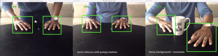
Flexible and Interactive Navigation in Synthesized
                        Environments

                     Vítor Emanuel Fernandes Magalhães

                Master in Informatics and Computing Engineering

Approved by:

President: Prof. Dr. Jorge Alves da Silva
External Examiner: Prof. Dra. Paula Maria Marques Moura Gomes Viana
Referee: Prof. Dr. Pedro Miguel Machado Soares Carvalho
22 July, 2020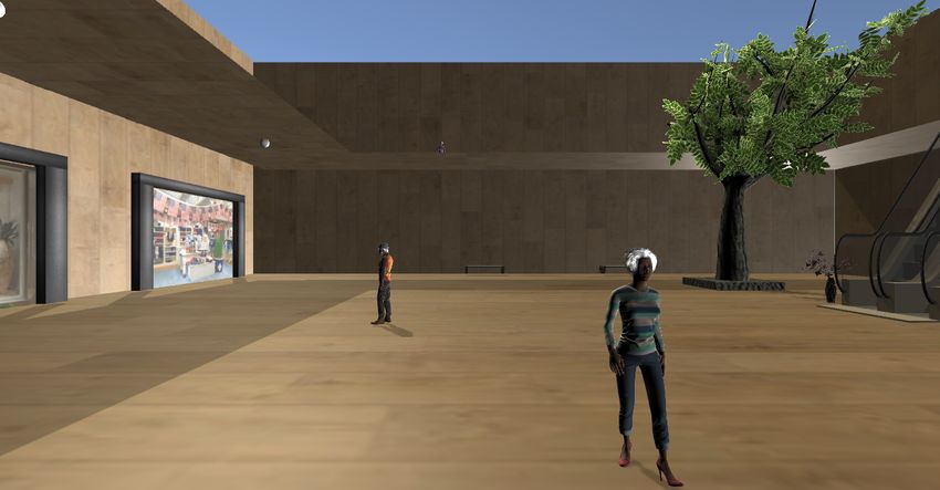
Resumo

    Tradicionalmente, o teclado e o rato são considerados as principais interfaces entre um uti-
lizador e um computador para a interação com ambientes 3D. No entanto, a sua utilização está
limitada à superfície em que é usada, como uma mesa. Este tipo de interação é invasivo, pois
restringue a liberdade que o utilizador tem para interagir e pode tornar-se repetitivo, portanto,
adaptar formas existentes de interação permitirá novas experiências para o utilizador. Além disso,
estes ambientes 3D estão cheios de conteúdo interativo, mas este é feito à mão e os ambientes são,
normalmente, criados sem qualquer tipo de descrição que facilita a sua criação.
    Esta dissertação visa a desenvolver um sistema flexível e não invasivo, capaz de interagir e vi-
sualizar uma cena sintetizada, que inclui descrições do seu conteúdo, focando no fornecimento de
mecanismos para interação com uma cena com restrições reduzidas. Para este fim, uma solução
que abrange Reconhecimento Gestual e Estimação de Poses é apresentada: O sistema captura
o gesto do utilizador utilizando uma câmara RGB, que é, de seguida, processado e, após ser
identificado corretamente, é enviado para a cena 3D, que gere a ação correspondente, permitindo
interação e navegação pelo ambiente. Ao interagir com determinados objetos, os utilizadores con-
seguem obter informações acerca destes objetos. Além disso, os diferentes ângulos das câmaras
interna permitem que os utilizadores vejam diferentes perspectivas da cena, alternando entre as
câmaras.
    Os principais desafios consistiram em garantir flexibilidade na captura de input do utilizador
usando uma câmara RGB e na definição e desenvolvimento de um conjunto de mecanismos de
interação que pudessem ser perfeitamente incorporados em cenas visuais sintetizadas, assim como
fazer a respetiva ligação de modo eficiente, garantindo o menor atraso possível no sistema.
    Diferentes técnicas de Reconhecimento Gestual e Estimação Pontual são examinadas, assim
como os tipos de câmaras que permitem capturar os movimentos do utilizador. Software variado
para sintetizar a cena 3D também é apresentado e a arquitetura do sistema, além de alguns detalhes
de implementação, são discutidos, com especial ênfase no primeiro.
    Um método de avaliação foi criado para voluntários poderem testar e fornecer comentários.
Os resultados dessa avaliação mostraram que os voluntários gostaram da imersão causada durante
a navegação no ambiente 3D, tornando-os mais interessados em explorar e interagir com a cena.
Apesar de o sistema por vezes misturar alguns gestos, nenhum atraso foi sentido assim que o
sistema identificasse o gesto.
    Apesar da rara identificação incorreta dos gestos, o sistema desenvolvido oferece uma inter-
ação não invasiva com ambientes 3D. Associado às descrições dentro destes ambientes, o sistema
estabelece uma forma cativante para utilizadores navegarem e interagirem com uma cena virtual e
o seu conteúdo disponível.

                                                 i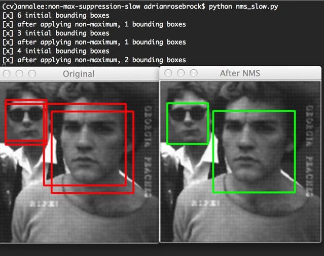
ii
Abstract

     The keyboard and mouse are considered the main interface between a user and a computer,
when interacting with 3D environments. However, their use is limited as they’re applied to a
surface, such as a table. This type of interaction is considered invasive, due to restricting the
user’s freedom to interact, and can become monotonous, therefore, adjusting existing ways to
interact will increase user experience. Moreover, these 3D environments are filled with interactive
content, but this content is hand made and the environments are usually built without any kind of
description which can facilitate the creation process.
     This dissertation aims to develop a flexible and non-invasive system capable of interaction and
visualization of a synthesized scene, which includes descriptions for its content, with focus on
providing mechanisms for interacting with a scene with reduced constraints. To achieve this, a
solution involving Gesture Recognition and Pose Estimation is presented: The developed system
captures the user gesture using an RGB camera, which is then processed and, after correct identi-
fication, is sent to the scene, which handles the corresponding action, allowing for interaction and
navigation of the environment. By interacting with certain objects, users can obtain information
regarding these objects. Furthermore, different camera angles inside the virtual scene allow users
to analyse different perspectives, by switching between the virtual cameras.
     The main challenges comprised in guaranteeing flexibility in capturing the user input using
an RGB camera and the definition and development of a set of interaction mechanisms that can
be seamlessly incorporated into synthesised visual scenes, as well as connecting the previous two
efficiently, guaranteeing the smallest amount of delay in the system.
     Different Gesture Recognition and Pose Estimation techniques are examined, in addition to
the types of cameras that allow capturing of the user movements. Different software for the Scene
Synthesis is also presented and the architecture of the system, as well as some implementation
details, are also discussed, with a specialized focus on the former.
     An evaluation methodology was created so that volunteers could test and provide feedback.
The results of the evaluation showed that the volunteers were engaged when navigating in the 3D
environment, making them more engrossed and attentive to explore and interact with the environ-
ment further. Despite the system occasionally intermingling a few gestures, no delays were felt as
soon as the system correctly identified the gesture.
     In spite of the rare incorrect identification of the gestures, the system offers a non-restricted
interaction with 3D environments. Combined with the descriptions of the scene, it establishes an
alluring way for users to navigate and interact with a virtual scene and its content.

   Keywords: Computer Vision, 3D, Interaction, Game Engines
   Areas: CCS - Computing methodologies - Artificial intelligence - Computer vision;
   CCS - Human-centered computing - Human-centered computing - Interaction techniques -
Gestural input;

                                                 iii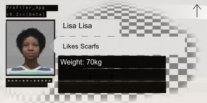
iv
Acknowledgements

    I would like to thank my supervisors, Professor Luís Côrte-Real, Pedro Carvalho and Américo
Pereira, from INESC TEC, for guiding me during the internship preceding this dissertation, and
for all the help and support throughout its planning and realization.
    My internship colleague, Ricardo Carvalho, with whom I spent many hours discussing the
nature of our dissertations, was instrumental in the improvement of the developed system.
    I wish to express my deepest gratitude to my parents, Cidália and Aníbal, and my brother
Pedro, for their continued support throughout the years, and to my friends and colleagues, in
particular to Antero Gandra, Alexandre Martins, Bernardo Leite, Diogo Teixeira, Fábio Azevedo,
João Esteves, José Pedro Martins, José Crisanto Magalhães, José Diogo Martins, Mariana Dias,
Mariana Neto, Ricardo Lopes, Tiago Santos and Xénia Lazera, which had to endure my nonsense
but made sure I was entertained and happy. Last but not least, I’d like to acknowledge Luke
Lafayette, whose encouragement and kindness was the foundation for the writing of this document.
    To all the mentioned entities, I am very grateful. Thank you.

Vítor Magalhães

                                               v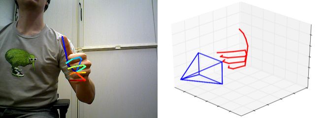
vi
‘No Cost Too Great”
      Pale King, Hollow Knight

vii
viii
Contents

1   Introduction                                                                                                                                                  1
    1.1 Context and Motivation . . . . . . . . . . . . . . . . . . . . . . . . . . . . . . .                                                                      1
    1.2 Objectives . . . . . . . . . . . . . . . . . . . . . . . . . . . . . . . . . . . . . .                                                                    2
    1.3 Dissertation Structure . . . . . . . . . . . . . . . . . . . . . . . . . . . . . . . .                                                                    3

2   Literature Review                                                                                                                                              5
    2.1 Introduction . . . . . . . . . .              .   .   .   .   .   .   .   .   .   .   .   .   .   .   .   .   .   .   .   .   .   .   .   .   .   .   .    5
    2.2 Input Capture . . . . . . . . .               .   .   .   .   .   .   .   .   .   .   .   .   .   .   .   .   .   .   .   .   .   .   .   .   .   .   .    5
         2.2.1 RGB Cameras . . . .                    .   .   .   .   .   .   .   .   .   .   .   .   .   .   .   .   .   .   .   .   .   .   .   .   .   .   .    6
         2.2.2 RGB-D Cameras . . .                    .   .   .   .   .   .   .   .   .   .   .   .   .   .   .   .   .   .   .   .   .   .   .   .   .   .   .    6
         2.2.3 Stereo Cameras . . . .                 .   .   .   .   .   .   .   .   .   .   .   .   .   .   .   .   .   .   .   .   .   .   .   .   .   .   .    6
    2.3 Gesture Recognition . . . . .                 .   .   .   .   .   .   .   .   .   .   .   .   .   .   .   .   .   .   .   .   .   .   .   .   .   .   .    7
         2.3.1 Hand Detection . . . .                 .   .   .   .   .   .   .   .   .   .   .   .   .   .   .   .   .   .   .   .   .   .   .   .   .   .   .    7
         2.3.2 Tracking . . . . . . .                 .   .   .   .   .   .   .   .   .   .   .   .   .   .   .   .   .   .   .   .   .   .   .   .   .   .   .    8
         2.3.3 Classification . . . . .               .   .   .   .   .   .   .   .   .   .   .   .   .   .   .   .   .   .   .   .   .   .   .   .   .   .   .    8
         2.3.4 Hand Pose Estimation                   .   .   .   .   .   .   .   .   .   .   .   .   .   .   .   .   .   .   .   .   .   .   .   .   .   .   .    9
    2.4 Interaction Synthesis . . . . .               .   .   .   .   .   .   .   .   .   .   .   .   .   .   .   .   .   .   .   .   .   .   .   .   .   .   .   11
    2.5 Discussion . . . . . . . . . . .              .   .   .   .   .   .   .   .   .   .   .   .   .   .   .   .   .   .   .   .   .   .   .   .   .   .   .   12

3   Proposal and Implemented System                                                                                                                               13
    3.1 Problem and Proposed Solution .                   .   .   .   .   .   .   .   .   .   .   .   .   .   .   .   .   .   .   .   .   .   .   .   .   .   .   13
    3.2 System Architecture . . . . . . .                 .   .   .   .   .   .   .   .   .   .   .   .   .   .   .   .   .   .   .   .   .   .   .   .   .   .   15
        3.2.1 Input Capture . . . . . .                   .   .   .   .   .   .   .   .   .   .   .   .   .   .   .   .   .   .   .   .   .   .   .   .   .   .   15
        3.2.2 Gesture Classification .                    .   .   .   .   .   .   .   .   .   .   .   .   .   .   .   .   .   .   .   .   .   .   .   .   .   .   19
        3.2.3 Action Correspondence .                     .   .   .   .   .   .   .   .   .   .   .   .   .   .   .   .   .   .   .   .   .   .   .   .   .   .   23
        3.2.4 Scene Processing . . . .                    .   .   .   .   .   .   .   .   .   .   .   .   .   .   .   .   .   .   .   .   .   .   .   .   .   .   26
        3.2.5 Scene Synthesis . . . . .                   .   .   .   .   .   .   .   .   .   .   .   .   .   .   .   .   .   .   .   .   .   .   .   .   .   .   26
    3.3 Implementation . . . . . . . . .                  .   .   .   .   .   .   .   .   .   .   .   .   .   .   .   .   .   .   .   .   .   .   .   .   .   .   28
        3.3.1 Development Tools . . .                     .   .   .   .   .   .   .   .   .   .   .   .   .   .   .   .   .   .   .   .   .   .   .   .   .   .   28
        3.3.2 Definitions . . . . . . .                   .   .   .   .   .   .   .   .   .   .   .   .   .   .   .   .   .   .   .   .   .   .   .   .   .   .   28
        3.3.3 Modules . . . . . . . .                     .   .   .   .   .   .   .   .   .   .   .   .   .   .   .   .   .   .   .   .   .   .   .   .   .   .   29
        3.3.4 Descriptions Files . . .                    .   .   .   .   .   .   .   .   .   .   .   .   .   .   .   .   .   .   .   .   .   .   .   .   .   .   31

4   Experiments and Results                                                                                                                                       33
    4.1 Experiments . . . . .     .   .   .   .   .   .   .   .   .   .   .   .   .   .   .   .   .   .   .   .   .   .   .   .   .   .   .   .   .   .   .   .   34
    4.2 Evaluation . . . . . .    .   .   .   .   .   .   .   .   .   .   .   .   .   .   .   .   .   .   .   .   .   .   .   .   .   .   .   .   .   .   .   .   35
    4.3 Results . . . . . . . .   .   .   .   .   .   .   .   .   .   .   .   .   .   .   .   .   .   .   .   .   .   .   .   .   .   .   .   .   .   .   .   .   35
    4.4 Observations . . . .      .   .   .   .   .   .   .   .   .   .   .   .   .   .   .   .   .   .   .   .   .   .   .   .   .   .   .   .   .   .   .   .   38

                                                                  ix
x CONTENTS 5 Conclusions and Future Work 39 A Versions of development tools 41 B Modules Code 43 B.1 Input Capture . . . . . . . . . . . . . . . . . . . . . . . . . . . . . . . . . . . . 43 B.2 Gesture Classification . . . . . . . . . . . . . . . . . . . . . . . . . . . . . . . . 43 B.3 Action Correspondence . . . . . . . . . . . . . . . . . . . . . . . . . . . . . . . 44 B.4 Scene Processing . . . . . . . . . . . . . . . . . . . . . . . . . . . . . . . . . . 45 B.5 Socket Messages . . . . . . . . . . . . . . . . . . . . . . . . . . . . . . . . . . 47 C 3D Scene content 49 C.1 3D Models . . . . . . . . . . . . . . . . . . . . . . . . . . . . . . . . . . . . . 49 C.2 Textures . . . . . . . . . . . . . . . . . . . . . . . . . . . . . . . . . . . . . . . 49 D Volunteer Test Results 51 References 59
List of Figures
1.1 Usage of VR on military training (adapted from Robots.net [4]) . . . . . . . . . . 2
2.1 Example of RGB, RGB-D and Stereo Cameras, respectively . . . . . . . . . . . 5
2.2 Detector in action (adapted from Victor Dibia’s HandTracking [24]) . . . . . . . 8
2.3 Leap Motion Controller (adapted from Ultraleap [30]) . . . . . . . . . . . . . . . 9
2.4 3D hand pose (adapted from ColorHandPose3D [36]) . . . . . . . . . . . . . . . 11
3.1 Abridged Dissertation Scheme . . . . . . . . . . . . . . . . . . . . . . . . . . . 14
3.2 Visual Representation of the System . . . . . . . . . . . . . . . . . . . . . . . . 15
3.3 Non-Maximum Suppression (adapted from PyImageSearch [54]) . . . . . . . . . 16
3.4 SSD Architecture (adapted from Medium [55]) . . . . . . . . . . . . . . . . . . 17
3.5 Feature Pyramid Networks architecture (adapted from TowardsDataSciene [57]) . 18
3.6 21 detected Keypoints of a gesture . . . . . . . . . . . . . . . . . . . . . . . . . 20
3.7 Example of Curl Difference on the Index Finger . . . . . . . . . . . . . . . . . . 20
3.8 Example of Direction calculation in the Thumb . . . . . . . . . . . . . . . . . . 22
3.9 Example of Direction calculation in the Ring Finger . . . . . . . . . . . . . . . . 23
3.10 Example of Direction calculation in the Index Finger . . . . . . . . . . . . . . . 24
3.11 User Interface of Decision . . . . . . . . . . . . . . . . . . . . . . . . . . . . . 26
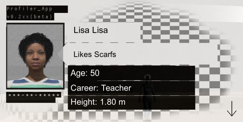
3.12 Information UI . . . . . . . . . . . . . . . . . . . . . . . . . . . . . . . . . . . 27
3.13 Human Head Degrees of Freedom (adapted from Luzardo et al. [71]) . . . . . . . 29
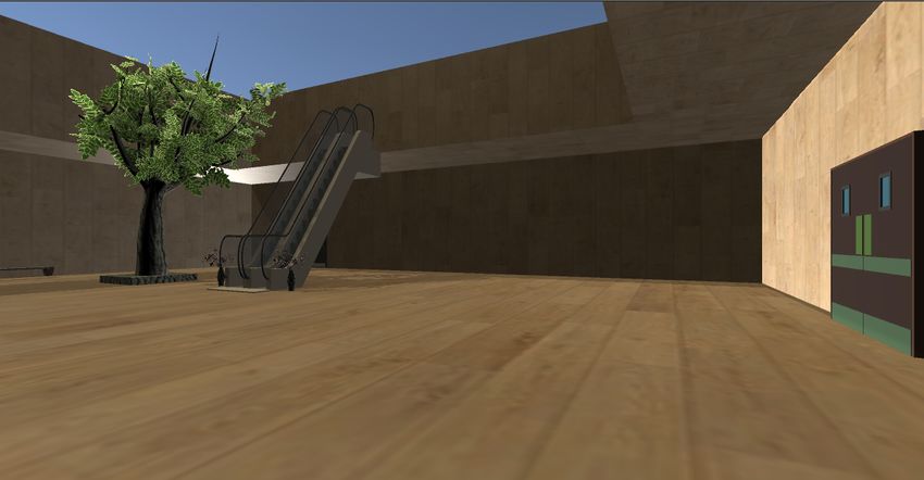
4.1 Scene visualized through the perspective of the first two cameras . . . . . . . . . 33
4.2 Viewing of the stores and some of the animated people . . . . . . . . . . . . . . 34
4.3 Form example filled by volunteers . . . . . . . . . . . . . . . . . . . . . . . . . 36
D.1 Results of the Going Forwards question . . . . . . . . . . . . . . . . . . . . . . 51
D.2 Results of the Going Backward question . . . . . . . . . . . . . . . . . . . . . . 52
D.3 Results of the Looking Right question . . . . . . . . . . . . . . . . . . . . . . . 53
D.4 Results of the Looking Left question . . . . . . . . . . . . . . . . . . . . . . . . 54
D.5 Results of the Going Up question . . . . . . . . . . . . . . . . . . . . . . . . . . 55
D.6 Results of the Going Down question . . . . . . . . . . . . . . . . . . . . . . . . 56
D.7 Results of the Interaction question . . . . . . . . . . . . . . . . . . . . . . . . . 57
D.8 Results of the Free Roam question . . . . . . . . . . . . . . . . . . . . . . . . . 58
xixii LIST OF FIGURES
List of Tables

 2.1   Game Engines Table . . . . . . . . . . . . . . . . . . . . . . . . . . . . . . . .     12

 3.1   Actions and Gestures Table . . . . . . . . . . . . . . . . . . . . . . . . . . . . .   25

                                             xiii
xiv LIST OF TABLES
Abbreviations and Symbols

2D       Two Dimensional
3D       Three Dimensional
API      Application Programming Interface
COCO     Common Objects in Context
CNN      Convolutional Neural Network
FPN      Feature Pyramid Network
FSM      Finite State Machine
GAN      Generative Adversarial Networks
GR       Gesture Recognition
HPG      Hand Pose Discriminator
HPG      Hand Pose Estimator
HPG      Hand Pose Generator
HTML     Hypertext Markup Language
JS       JavaScript
JSON     JavaScript Object Notation
N/D      Not Disclosured
PS       Playstation
PWA      Progressive Web App
RANSAC   Random Sample Consensus
RGB      Red Green Blue
RGB-D    Red Green Blue - Depth
SDK      Software Development Kit
SSD      Single Shot Detector
VGG16    Visual Geometry Group 16
VR       Virtual Reality

                                       xv
Chapter 1
Introduction
1.1 Context and Motivation
Computer-generated environments have been developed for many different uses, including
designing three dimensional buildings and videogame scenarios, as well as reconstructing monu-
ments, such as the Notre Dame. With new technologies, modelling lets creators build inanimate
objects, life-like creatures or even full-scaled dynamic environments, like a football match and a
shopping centre, whether they exist in reality or not.
3D environments are important as they permit users to immerse themselves in an assortment
of scenarios through navigation and exploration, such as Virtual Museums, which are a concept
primarily used to enhance the experience through interactivity, as explored by Geser and Nic-
colucci [1]. For example, Google has a collection of virtual museums which can be explored by
anyone for free [2]. However, the way we generally interact with these environments has been
the same for some time, which discourages any new form of interaction or adaptations of already
existing means of interaction. In 3D scenes, interaction is mostly based on the movement of the
mouse and keyboard or with touchscreens. Not only are these types of interactions becoming
repetitive, since the actions aren’t usually varied, but they also tend to belong to systems with
invasive interactions. This downgrades the experience of the user, due to restricting their freedom.
For example, the mouse and keyboard can be considered restrictive since they are limited to a
surface’s functionality. Juxtaposed with these are systems with non-invasive interactions which
are advantageous due to their refinement and advancement of user experience as they minimize
intrusions during any interaction. A hands free system is the most notable example, such as the
one developed by Horvitz and Shwe [3], which allows for the user to have a more relaxed and
stimulated interlinkage, due to not being bound to a surface. To surmise, adapting existing non-
invasive mechanisms to improve interactions with virtual scenes will grant users new and more
diverse opportunities to connect to the environment, making it more entertaining and engaging to
anyone.
Developments on Gesture Recognition and Virtual Reality have helped to cement new ways to
be immersed in virtual scenarios and these technologies can be used to enhance interaction with
12 Introduction
Figure 1.1: Usage of VR on military training (adapted from Robots.net [4])
scenarios by removing limitations of the keyboard and mouse. For example, since its creation, Vir-
tual Reality allows this type of immersion for military usage, as seen in Figure 1.1. It also helps
managing anxiety levels [5] or designing intricate products, such as aircrafts [6], with its most
popular application being video games. In another example, Gesture Recognition allows synergy
between humans and robots, by making gestures for robots to perform through programmable
actions communicated through mirroring and mimicry. Using these tools acts as an asset to the
enrichment and betterment of the user’s experience and permits the user more fulfilling and im-
mersive interactions. There are also multiple scenarios where users can use these tools, such as
security, monitoring and representing information. For example, during a football match, these
tools can function to provide information about the players, while administering and monitoring
spectators.
1.2 Objectives
The objective of this dissertation is to provide a flexible and non-invasive mechanism to in-
teract with and visualise a 3D virtual scene. To reach this end, the following sub-objectives were
achieved:
• Definition and implementation of a module for the automatic recognition of a set of gestures
using captured visual information in less restricted scenarios;1.3 Dissertation Structure 3
• Implementation of mechanisms for associating interaction points with an automatically syn-
thesised visual scene, filled with information;
• Integration of gesture recognition with the visual scene to enable an interactive navigation.
The main challenges consisted in guaranteeing the flexibility of capturing the user’s hand ges-
tures using video cameras and defining the mechanisms that allowed the hand pose to be translated
into input, in order to interact with the virtual environment. Correctly capturing the user input and
translating it into actions was a difficulty, since the action must be correct according to the user’s
gesture. Moreover, when making a gesture, the user expects the visualization of the actions as soon
as possible; ergo, any latency between making a gesture, processing it, sending it to the scene and
then executing the corresponding action can decrease the user’s experience. Because these ac-
tions interact with the scene, the generation of 3D content must be precise in order to maintain
immersivity and consistency. The mentioned method of Gesture Recognition and Interpretation
worked as an interface between the user and the virtual scene. A setup scene based on a shopping
center was created to test all functionalities, which includes basic 3D objects and free 3D models
to enrich the environment. The proposed solution allows a greater immersion on exploring a 3D
environment and, most importantly, motivate users to experience new ways to connect with the
objects in the scene, since the users’ interactions aren’t restricted to a surface, as is the case of the
keyboard and mouse, thus being much more relaxed.
1.3 Dissertation Structure
In addition to the introduction, this document contains six other chapters. Chapter 2 explores
the state of the art and presents related works. In Chapter 3, the main problem that is approached
in this dissertation is more fundamentally explored and the proposed solution is presented, fol-
lowed by the architecture of the developed system which is presented alongside all implementa-
tion details as well as definitions related to the created system are explained. In Chapter 4, exper-
iments made throughout development and obtained results are discussed, alongside the evaluation
methodology for said results. Finally, in Chapter 5, conclusions and future work are presented.4 Introduction
Chapter 2

Literature Review

2.1     Introduction
    The usage of non-invasive interactions requires tools that minimize any restriction for the user.
These tools should capture user input, process it and then present its result in the scene; ergo, they
must be discussed and identified in order to understand what can be used for each objective. This
chapter is divided into Input Capture, Gesture Recognition and Interaction Synthesis: each section
dwells into tools explored and articles read that fit into the scope of the dissertation.

2.2     Input Capture
    This section covers the necessary tools to capture user input. Due to the requirement for
reducing the usage of invasive input mechanisms, the usage of cameras is investigated for gesture
recognition application, by capturing the input made by the user. After the input is properly
captured by a video camera, it must be processed via Gesture Recognition.
    There are three categories of cameras that will be discussed due to their capability of capturing
user input information: RGB, RGB-D and Stereo Cameras. For each, the type will be described,
with their pros and cons discussed with some application examples. Fig. 2.1 presents an example
of each type. The first one is a Logitech RGB camera [7], whereas the second one is a RGB-D
camera from Microsoft called Kinect [8]. The latter is the Intel Realsense Stereo camera from
Intel [9].

             Figure 2.1: Example of RGB, RGB-D and Stereo Cameras, respectively

                                                   5
6 Literature Review
2.2.1 RGB Cameras
An RGB Camera is able to capture colored digital frames and they have no dedicated sensor
to perceive depth. These cameras are easily obtainable in the market, since they are cheap, and
most laptops have one. In order to obtain the sense of depth, one can identify a marker for the
camera to track, by calibrating the camera, or one can use two RGB Cameras and compare the
captured frames [10] by calculating triangulation between them. Saxena et al. [11] were able to
generate depth maps from still images with a learning approach and then apply those maps to
create 3D models. Regazzoni et al. [10] developed a system using six Sony PS Eye RGB Cameras
and concluded that, while they are able to capture a large environment, it required a uniform and
light color background.
2.2.2 RGB-D Cameras
An RGB-D Camera has a sensor that is able to obtain the color image and depth perception.
These cameras aren’t as cheap as generic RGB cameras, for example, the Microsoft Kinect Sensor
costs around 150 euros whereas RGB cameras can cost as low as 30 euros. Spinello and Arras [12]
used a Microsoft Kinect Sensor and, according to them, the sensor has an infrared camera, an
infrared projector and a standard RGB camera. To measure the depth, it follows the principle of
structured infrared light. This process [13] involves projecting a pattern, such as grids or horizontal
bars, and the way they deform when striking the surfaces allows the calculation of depth.
Regazzoni et al. [10]’s system also included two Microsoft Kinect for Windows Cameras and
concluded that the setup time is smaller compared to the PS Eye cameras, but Kinect isn’t as
sensible to light as the PS Eye and the captured information files are larger.
2.2.3 Stereo Cameras
A Stereo Camera has two or more lenses and allows the simulation of human binocular/stereo
vision, thus, it is more expensive than the previously discussed cameras. For example, the Intel Re-
alsense costs around 320 euros. O’Riordan et al. [14] identify three types of stereo vision: Passive,
which captures static objects; Active, which shares principles with the prior but allows dynamic
motion of the cameras and objects and Multiple-Baseline, which uses various cameras to capture
several images that are matched together to improve accuracy. Kim et al. [15] used a Bumblebee
Stereo for 3D range data acquisition, which is calculated after the two sensors are rectified. They
experimented by capturing images of an irregular surface and calculating the range data via stereo
system of the camera. The data was used for the neural network they were applying for a multiple
plane area detection. Liu and Kehtarnavaz [16] created a system to recognize gestures using stereo
images captured by a stereo webcam to achieve robustness under realistic lighting conditions. By
comparing the accuracy between a single image and two stereo images, both achieved a similar
frame rate, but, when merging both stereo images, the average detection rate improved by almost
60 %.2.3 Gesture Recognition 7
2.3 Gesture Recognition
Gesture Recognition is described as the process of identifying the gesture performed by a user
and usually has the aim of interpret certain commands [17].
Gestures are expressive body motions which include the movement parts of the body such
as the fingers, hands, arms, head, face or even the whole body in order to transmit information
or interact with an environment. Gesture recognition has a wide range of possible applications,
including recognizing sign language, teaching young children to interact with computers and lie
detection.
Since gestures are ambiguous, there is a challenge in defining the same meaning for the dif-
ferent gestures and vice-versa, for example, a hand facing forward slightly above the head can
represent a greeting ( "Hello") or an appreciation ("Thank you").
Gestures can be static or dynamic. As the name indicates, static gestures are simply poses and
dynamic gestures have prestroke, stroke and poststroke phases, in order to represent the complete
gesture.
To detect and determine these aspects, tracking devices are required. These can be attached
to the user, like gloves, or they can be cameras which use computer vision techniques in order to
detect and recognize the gestures [18]. This dissertation will focus on the latter as it is less invasive
and does not require users to have very specific devices.
Gesture Recognition typically has three different phases: Hand Detection, where the hand is
recognized, Tracking, where the hand is tracked and its movement is processed and Classifica-
tion, where the gesture is classified. Besides these phases, Hand Pose Estimation is also discussed.
2.3.1 Hand Detection
Image segmentation is the operation of partitioning an image into several segments, in order
to simplify the original image [19]. The objective is to simplify or change the representation of
an image into something more meaningful and easier to analyze. Patrick de Sousa [20] analised
several methods in order to recognize gestures for Human-Robot interaction. According to him,
the most popular type of segmentation is skin-color based. The downside of this method is that the
user cannot use gloves and skin colored objects can’t appear in background as well as some being
susceptible to light variation. Park and Lee [21] developed a system where the hand was detected
based on the color of the face, but not all users would like to have their face detected. Cerlinca
and Pentiuc made a real time 3D hand detection and assumed the hands were always closer to
sensor than the head [22]. Despite being based on head location, one can also assume that the
hands will always closer to the sensor in order to navigate and interact with the scene. The use of
skin-color and depth information for a real-time 3D hand recognition has also been used by Bergh
and Gool [23]. By using a Time of Flight and an RGB camera, they were able to detect the face of
the user and the distance between them and the camera. With the calculated distance, the system
is able to discard background objects.8 Literature Review
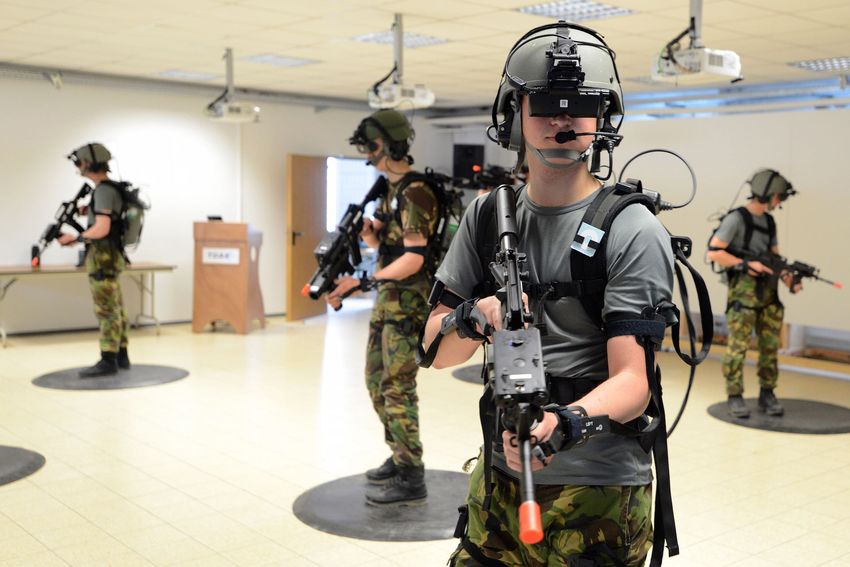
Figure 2.2: Detector in action (adapted from Victor Dibia’s HandTracking [24])
Victor Dibia [24] developed a real-time Hand Detection and Tracking system using Neural
Networks, as they are trained to perform on several environments with challenges such as poor
lighting, occlusion and noisy backgrounds, as seen in Fig. 2.2. He also published the code as
Open Source, available online on Github.
2.3.2 Tracking
After segmenting the image, the next step is to track the hand and to detect the corresponding
gesture. This is used so the system knows the location of the hand and to avoid further segmenta-
tion costs.
Markov models have been used to identify a number of gestures to control an application [25].
Ramey et al. [26] classified a gesture of a waving hand, by using a finite state machine. A Con-
volutional Neural Network (CNN) was proposed [27] to detect gestures from different inputs with
depth, color or stereo-IR sensors, achieving an 83.8 % accuracy when recognizing gestures. To
implement a real-time hand tracking, Chen et al. [28] used a region growing technique with the
seed point on the estimated center of the hand based on the previous frame. The estimation of
the first seed was obtained by a hand click detection method in order to start the tracking. As
mentioned in section 2.3.1, Dibia’s system is able to track the hand movement as well as detect
it [24].
There are sensor devices that allow tracking, such as the Leap Motion [29], developed by
Ultraleap. It is a Hand Tracking device that uses hand and finger motions as input, analogous to
a mouse, but requires no hand contact or touching, as seen in figure 2.3. It’s a cheap device but
users are dependant of the position of the sensor, which limits the area to be tracked. Due to this
limitation, it’s not a good device to be used on this dissertation.
2.3.3 Classification
The classifier plays a major role in the system: its task is to identify the gesture based on the
result of the hand detection and tracking sections. According to Sonkusare et al. [17], the input
features can be compared with features of a database. Molchanov et al. [27] perform classifi-
cation by splitting the captured video feed into clips of a certain length and computing a set of2.3 Gesture Recognition 9
Figure 2.3: Leap Motion Controller (adapted from Ultraleap [30])
class-conditional probabilities. They also consider calculating the final classification score with a
support vector machine, achieving a final accuracy of 83.8% when classifying gestures. A CNN
was used by Jiang et Al. [31] to detect ASL (American Sign Language) dataset. To test it, they
used five different gestures, obtaining a 96.01% accuracy on recognizing gestures. Patrick de
Sousa [20] used a simple Finite State Machine (FSM) for each gesture to be detected. It was de-
signed according to the movement of the proposed gestures. Hidden Markov Models were also
used to classify Indian sign language [32], obtaining an accuracy of 89.25 %.
2.3.4 Hand Pose Estimation
Hand pose estimation is the procedure of modeling the human hand as a set of some parts, for
example, the fingers, and calculating their positions in the image of a hand [33]. Its application
is vast for a wide range of field. For example, the area of robotics can greatly benefit with this
technique, since users can control a robotic hand using specific poses that command the machine.
In the medical field, this can be extended for a doctor to operate during a surgery or even a student
to practice. Hands are usually modeled as a number of joints and, by finding the position of the
joints, the real hand pose can be estimated. The most popular number of joints to model hands is
21, although there are some models which use 14 and 16 [33].
According to Doosti, there are two type of networks used in the Hand Pose Estimation prob-
lem: Detection-Based and Regression-based [33]. In the first, for every existing joint, the model
produces a probability density map. Assuming the network uses a 21-joints model, each image
will produce 21 different probability density maps in the form of heatmaps. To find the exact
location of each joint, one only needs to use a argmax function on the corresponding heatmap.
In comparison, regression-based method attempts to directly estimate the position of each joint.10 Literature Review
Assuming the model composed by 21 joints, it should have 3 x 21 neurons in the last layer to
predict the 3D coordinates of each joint. Training a regression-based network requires more data
and training iterations because of to the high non-linearity. However, producing a 3D probability
density function for each joint is a substantial task for the network, therefore, regression-based
networks are utilized in tasks of 3D hand pose estimation.
The two main methods for Hand Pose Estimation are Depth and Image based methods. The
first one makes use of depth map images, which was traditionally the main method for estimation.
Based on a depth map, Sinha et al. [34] used a regression-based method to find 21 joints in the
hand. They sought to learn the location of joints in each finger independently, so, they trained a
separate network for each finger to regress three joints on that finger. Despite using a depth map
to regress the coordinates, they also used RGB to isolate the hand and to remove all other pixels
included in the hand’s cropped frame.
Baek et al. were able to use Generative Adversarial Networks (or GAN) to estimate the hand
pose by making a one to one relation between depth disparity maps and 3D hand pose models [35].
GAN is a specific CNN that generates new samples based on the previous learned ones. It con-
sists of a discriminator and a generator network which are competing with each other: while the
discriminator network is a classifier trained to distinguish real and fake images, the generator, also
a convolutional neural network, generates fake images. The authors used a GAN, named Cyclic-
GAN, for transferring one image from one domain to another. In this context, one domain is the
depth map of the hand and the other is the 3D representation of the hand joints. They used a Hand
Pose Generator (HPG) and a Hand Pose Discriminator (HPD) in their model. The HPG generates
a hand, based on the 3D representation of the joints. Meanwhile, they used a Hand Pose Estimator
(HPE) whose objective is to generate the 3D hand pose, based on the input depth map. Thus, in
the training step, HPG, HPD and HPE are optimized to reduce the error of HPE and to increase
the consistency of the HPE-HPG combination. In the testing phase, the algorithm refines the 3D
model, guided by the HPG, to generate the best 3D model whose corresponding depth map is akin
to the input depth map.
The second method for Hand Pose Estimation is Image Based, which makes use of RGB
images. This is a significantly harder task because the data has its dimension reduced, which loses
some of the information, however, RGB cameras are more commonly used than RGB-D cameras.
These methods need to isolate the hand (segmentation) first and then pass the cropped image to
the network to estimate the pose.
Zimmerman and Brox developed a network, called ColorHandPose3D, which estimates a 3D
hand pose from a single RGB image [36], by detecting the associated keypoints from the joints
of the fingers, as seen in Fig. 2.4. The system uses the RGB image on the left and creates a 3D
hand pose, presented on the right. They used several different deep learning streams in order to
make a 3D estimation of hand joints using a single color image. The network uses PoseNet [37],
a detection-based network which produces one probability density function for each hand joint.
These predictions are in two dimensions and on the same coordinates of the input image. To
obtain a 3D estimation, Zimmerman et al. used a network named PosePrior to convert the 2D2.4 Interaction Synthesis 11
Figure 2.4: 3D hand pose (adapted from ColorHandPose3D [36])
predictions to the 3D hand estimation. PosePrior is a regression-based network, able of predicting
the coordinates of the joints followed by a normalization. In this step, the authors normalize the
distances of the joints, considering the farthest distance as 1 and dividing the other distances to
that number. Finally, they find a 3D rotation matrix such that a certain rotated keypoints is aligned
with the y-axis of the canonical frame.
The biggest issue regarding image-based methods is occlusion of the hand. Simon et. al [38]
used a multicamera approach to estimate the hand pose. First, they trained a weak hand pose
estimator with a synthesized hand dataset. Afterwards, they put a person in the center of the
panoptic and applied the hand pose estimator on all the cameras recording video. The algorithm
produces a slightly inaccurate pose estimation for all of these views. It functions in most of the
views, but in the ones in which the hand is occluded, it poorly works. In the next part, which the
authors called triangulation step, they converted their 2D estimation to 3D estimation to evaluate
their results. To estimate the correct 3D pose, for each joint, they used the RANSAC [39] algorithm
to randomly select 2D views and convert them to 3D. Then they kept the model with which most
of the views agree. Finally, in a reverse operation, they projected the 3D view to the pictures
and annotate that frame. Instead of manually annotating data, the authors used multiple views to
annotate the data for them. Then, with this annotated dataset originated from multiple views, they
trained the network again and made it more accurate. By repeating this process of annotation and
training, they ended up with a superior and accurate model and dataset of annotated hand poses.
2.4 Interaction Synthesis
This section covers tools that allow the generation of the 3D content from the scene, as well
as making the scene interactive by receiving the result of the Gesture Recognition.
A Game Engine is a software-development environment designed for people to build video
games. The core functionality typically provided by a game engine includes a rendering engine,
a physics engine or collision detection (and collision response), sound, scripting, animation, arti-
ficial intelligence, networking, streaming, memory management, threading, localization support,
scene graph, and may include video support for cinematics.12 Literature Review
Table 2.1: Game Engines Table
GR
Game Engine Author(s) Licence
Integration
Blend4Web Triumph [40] GPLv3 N/D
CryEngine Crytek [41] Royalties No
GameMaker YoYo Games [42] Shareware No
Godot Linietsky and Manzurr [43] Free No
jMonkey Engine jMonkey Team [44] BDS3 N/D
Ogre 3D Ogre Team [45] MIT No
Panda 3D Carnegie Mellon University [46] Free No
Three.js mrdoob [47] MIT N/D
Unity Unity Technologies [48] Free Yes
Unreal Engine 4 Epic Games [49] Free Yes
For this dissertation, the used game engine should support gesture recognition and virtual
reality integration. Table 2.1 sums up the searched engines and conclusions regarding the Gesture
Recognition. One can conclude that Unity and Unreal Engine 4 are able to integrate Gesture
Recognition, therefore, they’re the most capable engines to generate the content of the visual
scene as well as integrate the interaction mechanisms. They are also the most popular engines,
which come with regular updates and fixes from the developers.
2.5 Discussion
In order to capture the user input, the reached conclusion is that RGB and RGB-D cameras
are the best options, due to their inexpensiveness and ease of access to users. This is supported
by multiple studies. For instance, Regazzoni et al. [10] presented a study comparing both types of
cameras in terms of information captured from the scene. Dibia [24] also showed that this type of
cameras can be used to detect and track hands. More recently, Jiang et al. [31] presented a new
CNN architecture that was capable of detecting and classifying gestures.
These two systems use CNNs, which appear to be the most interesting technique to use for
Gesture Recognition. Hand Pose Estimation also seems to return the best results in terms of
accurately identifying a gesture. Finally, the most adequate Game Engines are Unity and Unreal
Engine 4, since they allow integration with Gesture Recognition.
Due to the context of the dissertation, many sources are from websites and usually regard
authors of Game Engines.Chapter 3
Proposal and Implemented System
This chapter is divided into three parts: In the first part, the Problem is discussed and a Pro-
posed Approach is presented; the second part details and discusses the Architecture of the Devel-
oped System, including a description of its modules along with their connections. Additionally,
the selected gesture dataset alongside the corresponding actions are also revealed; the third and fi-
nal part of this chapter serves to detail the system’s implementation. The used tools and definitions
are indicated, as well as the modules of the system and descriptions used for the objects inside the
3D scene.
3.1 Problem and Proposed Solution
Three dimensional environments have many uses, such as virtual museums and video games,
but the way we interact remains the same and this is usually part of systems with restrictive inter-
actions, which downgrades the user’s experience. Furthermore, these environments aren’t usually
built with the assistance of descriptions to facilitate the process.The main problem consisted on
the usage of invasive interaction mechanisms, due to restricting the user’s freedom to interact and
the lack of adoption of descriptive scenes, as they can easily translate the environment of a scene.
These restrictions can also limit the input capture, thus, the automatic connection between the in-
put and the 3D environment is impacted. The consolidation between the non-invasive mechanisms
and descriptive scenes allows an easier creation of 3D environments and simpler interactions with
it.
The proposed solution aims to uplift the use of non-invasive interaction mechanisms in order
to not only reduce user’s limitations when interacting with a scene, but also increase the im-
mersiveness of 3D visualization, by enabling interactions between the user and the scene. The
solution also includes the creation of interaction mechanisms and their integration with the scene.
To demonstrate the usability of such a solution, a system was developed that enables these inter-
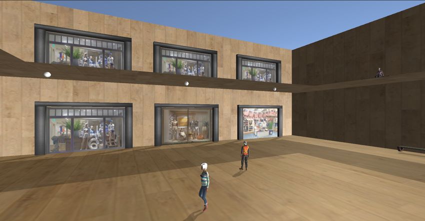
actions. A virtual scene, based on a shopping center, was also defined, composed by objects and
virtual cameras. The objects correspond to elements present in the surroundings, such as benches,
vases and even people. Some of these objects may be interacted with: by selecting an object, a
1314 Proposal and Implemented System
user may obtain information about it or even switch to the perspective of that object, if it contains
said functionalities. The virtual cameras permit the user to switch between perspectives inside the
scene: this way, they can find new details and quickly navigate between the various cameras.
Users are able to navigate and interact with the scene, gesturing with their hands. These
gestures are captured by an RGB video camera and then processed by the system and sent to
the scene in the shape of actions, but the traditional way of using the keyboard and mouse is
maintained if the users wish to use them.
The system can be summed up in two components, as presented in Fig. 3.1: one that captures
and handles user input and another that processes the scene and actions from the user. The first
component captures any hand gesture with an RGB video camera, classifies it and then sends the
corresponding action to the second component. This one contains a scene with objects and virtual
cameras, as well as information about them, and converts the actions from the previous component
into an interaction inside the 3D scene.
Figure 3.1: Abridged Dissertation Scheme
Initially, tests took place to define the Game Engine to be used as well as an analysis of
available projects that could serve as a base for the system. A 3D scene was created throughout
development, with interactive objects and different camera angles.
After having a basis for recognizing gestures with an RGB camera and classifying them, the
next step was to establish communication with the Game Engine and translate a couple of gestures
into interactions. As the communications were settled, all actions inside the scene were developed,
including movement, changing between virtual cameras and interacting with objects. Afterwards,
objects’ descriptions were defined to be read by the system.
Finally, the creation of the complete set of gestures followed shortly after, mapping all possible
interactions from the user. Most gestures that were defined took practical and regular poses in
consideration, as well as making sure the gestures wouldn’t intermingle with each other.
Throughout the dissertation, experiments were made and volunteers were requested to operate
the developed methods against the Keyboard and Mouse method, providing feedback.3.2 System Architecture 15
3.2 System Architecture
The system is divided into several modules, each with their own functionality. A visual rep-
resentation of the system can be seen in Fig. 3.2. The Input Capture Module captures gestures
made by the user and translates them into poses, which are used by the Gesture Classification
Module to be classified. Once it’s classified, the Action Correspondence Module verifies the ges-
ture and sends an action in the form of a message to the Scene Processing Module. This Module
converts the message into an action inside the virtual environment, which, in turn, returns the end
result of the system in the Scene Synthesis Module. The successive use of these previous modules
allows the user to experience built-in mechanics to interact with a virtual scene.
Figure 3.2: Visual Representation of the System
3.2.1 Input Capture
The Input Capture Module is used to capture the user’s hand with an RGB camera and tran-
scribe its gesture into the user’s hand pose. The module uses two models from the Handpose
project [50]: a Palm Detector and a Hand Landmark Detector.
The Palm Detector receives an image and outputs bounding boxes of the detected palm. It is
based on a Single Shot MultiBox Detector [51], or SSD, a Neural Network capable of detecting
objects in images which uses multi-scale convolutional bounding box outputs attached to multiple
feature maps at the top of the network, allowing to efficiently model the space of possible box
shapes. It eliminates proposal generation and any pixel/feature resampling stages, encapsulating
all computation in a single network, while maintaining accuracy. SSD uses VGG16 [52] as the
base network. It’s a standard architecture used for high quality image classification and, in this
case, to extract feature maps, being located in the early network layers and truncated before any
classification layers.16 Proposal and Implemented System
The authors then add an auxiliary structure to the network to produce detections with the
following key features:
• Multi-scale feature maps - Convolutional layers are added to the end of the base network.
They decrease in size progressively and allow predictions of detections at multiple scales.
• Convolutional predictors for detections - Each added feature layer can produce a fixed-set
of predictions using convolutional filters.
• Default boxes and aspect ratios - Default bounding boxes are associated with a feature map
cell at the top of the network. The default boxes tile the feature map in a convolutional
manner, so that the position of each box relative to its corresponding cell is fixed.
Given the large number of boxes generated during a forward pass of SSD at inference time, it
is essential to prune most of the bounding boxes by applying a technique known as non-maximum
suppression to remove duplicate predictions pointing to the same object. Hosang et al. explain
that the algorithm selects high scoring detections and deletes close-by less confident neighbours
since they are likely to cover the same object [53], as seen in Fig. 3.3: the result greatly removes
duplicated bounding boxes that represent the same object. This also ensures only the most likely
predictions are retained by the network, while the noisier ones are removed.
Figure 3.3: Non-Maximum Suppression (adapted from PyImageSearch [54])3.2 System Architecture 17
Fig. 3.4 reveals the architecture of an SSD. It receives an image and the initial layers are based
on VGG16, which extracts feature maps, and detects objects using the other deeper layers. After
the detections, the non-maximum suppression removes duplicates, effectively reducing the number
of detections.
Figure 3.4: SSD Architecture (adapted from Medium [55])
Training an SSD and training a typical detector that uses region proposals differs in the as-
signment of ground truth information to specific outputs in the fixed set of detector outputs. For
an SSD, once the assignment is determined, the loss function and back propagation are applied
end-to-end. Training also involves choosing the set of default boxes and scales for detection as
well as hard negative mining and data augmentation strategies.
During training, each default box is corresponded to a ground truth detection and the network
is trained accordingly. For each ground truth box, a default box that varies location, scale and
aspect ratio is selected. First, each ground truth box is matched to a default box with the best
jaccard overlap. Then, the default boxes are matched to any ground truth with overlap higher than
a threshold (0.5). This simplifies the learning problem, allowing the network to predict high scores
for multiple overlapping default boxes rather than just one.
Three other strategies are used to enhance the training. The first one is Choosing a set of de-
fault boxes and scales, in order to handle different scales and obtain a diverse set of predictions.
The second strategy involves Hard negative mining: after matching, most default boxes are nega-
tive, which introduces a significant imbalance between positive and negative examples; ergo, this
technique balances the positive and negative examples, leading to a faster optimization and stable
training. The final technique is Data Augmentation, which makes the SSD more robust to various
object sizes and shapes.
The Palm Detector model trains the detection of the palm rather than the hand because esti-
mating bounding boxes of rigid objects like palms and fists is significantly simpler than detecting18 Proposal and Implemented System
hands with articulated fingers. Palms can be modelled using square bounding boxes (anchors)
ignoring other ratios, thus reducing the number of anchors by a factor of 3-5. Besides this, the
non-maximum suppression algorithm works for smaller objects, which boosts performance when
dealing with palms. However, the SSD alone isn’t enough to detect small objects (in this case,
the palms), with high precision. These objects can only be detected in higher resolution layers,
which are the leftmost layers, but these contain low-level features, like edges or color patches, that
are less informative for classification. In order to solve this, the model uses a similar approach to
the Feature Pyramid Networks [56], or FPN, to provide a bigger scene context awareness even for
small objects. FPN provides a Top-Down Pathway, as seen in Fig. 3.5 to construct higher resolu-
tion layers from a semantic rich layer, as well as Bottom-Up Pathway, which is what convolutional
networks usually use for feature extraction. With Bottom-Up, as the image gets processed, the se-
mantic value for each layer increases and the spatial resolution decreases. While the reconstructed
layers are semantically strong, the locations of objects are not precise after all the downsampling
and upsampling. Adding lateral connections between reconstructed layers and the corresponding
feature maps helps the detector predict the location better; ergo, FPN allows for a better small
object detection in lower resolution layers, further boosting the precision. The combination of
lateral connections and a Top-Down Pathway greatly increases accuracy. According to the authors
of FPN, it improves accuracy by 8 points on the COCO dataset and, for small objects, it improves
by 12.9.
Figure 3.5: Feature Pyramid Networks architecture (adapted from TowardsDataSciene [57])
Lastly, the Palm Detector model minimizes focal loss during training to support large amount
of anchors resulting from high scale variance. Focal Loss [58] focuses training on a sparse set of
hard examples and prevents the vast number of easy negatives from overwhelming the detector3.2 System Architecture 19
during training. According to Bazarevsky and Zhang, the authors of the model, the final model
achieves an average precision of 95.7% in palm detection [59].
In short, the Palm Detector model is based on the SSD, with a feature extractor based on FPN
to improve small objects detection. During training, the model minimizes focal loss to reduce the
number of easy negatives.
The second model, Hand Landmark Detector, works on the bounding boxes from the previous
model and makes all calculations based on this input. It’s a CNN regression model that performs
precise keypoint localization of 21 3D coordinates through a Regression-based method, as dis-
cussed in subsection 2.3.4 in chapter 2. These keypoints represent the 3D estimation of the hand’s
pose, which are then used by the Gesture Classification Module. The model learns a consistent
internal hand pose representation and is robust to partially visible hands and self-occlusions. To
obtain ground truth data, the authors manually annotated around 30 thousand real-world images
with 21 3D coordinates [59]. To better cover the possible hand poses and provide additional su-
pervision on the nature of hand geometry, they also rendered a high-quality synthetic hand model
over various backgrounds and map it to the corresponding 3D coordinates. In order to improve
training, they utilized a mixed training schema which uses both synthetic and real world data, re-
sulting in a significant performance boost, with a mean regression error normalize by palm size of
13.4%, whereas only real-world data resulted in 16.1% and the synthetic data in 25.7%.
3.2.2 Gesture Classification
The Gesture Classification Module is tasked with classifying the gesture the user performs. To
do so, it receives the 21 keypoints from the previous module, as seen in Fig. 3.6 and calculates the
estimations of the curls and orientations of each finger. It then compares the obtained estimations
with the known gestures in the dataset, saving all gestures with a confidence over a threshold.
The module begins by estimating the curls and orientations of each finger, using the received
keypoints. Firstly, it must calculate the slopes of each finger. Each finger has a set of four mapped
pair of points, in the form of indexes, which represent the connection between the finger’s joints.
For each pair of points from the set, the system calculates the slopes, using function 3.1, consider-
ing P1 and P2 as the two points from the pair:
(P1.y−P2.y)
arctan( (P1.x−P2.x) ) ∗ 180
Slope = (3.1)
π
Secondly, the system calculates the curls of the fingers. After obtaining the indexes like before,
the system gets the start, middle and end points of the finger. For example, the points of the thumb,
in Fig. 3.6, are the points 2, 3 and 4, respectively. These points correspond to the fingers’ joints
and are obtained by associating the indexes with the keypoints from the previous module.
To verify the curl of the finger, the distances between the three points are calculated (start to
middle, start to end and middle to end). Then, it determines the angle between the distances and20 Proposal and Implemented System
Figure 3.6: 21 detected Keypoints of a gesture
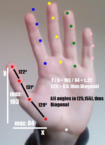
defines whether the finger is curled or not. Fig. 3.7 shows an example of the different detected
curls in the Index finger alongside the obtained degrees on each curl.
To distinguish each possible curl, limits were defined which represent the angle between the
palm of the hand and the finger. As the finger curls, the aforementioned angle decreases. During
performed tests, the finger is half curled up to angle values close to 60o and completely curled
below that, while 130o was the minimum angle for the finger to be considered stretched. The curl
distinction is made as follows:
• If the angle is higher than the No Curl Limit (130o ), it is not curled;
• If the angle is higher than the Half Curl Limit (60o ), it is half curled;
• If the previous two don’t apply, it is curled.
Figure 3.7: Example of Curl Difference on the Index FingerYou can also read