Test Methods for Interrogating Autonomous Vehicle Behaviour - Findings from the HumanDrive Project - HORIBA MIRA Richard Hillman
←
→
Page content transcription
If your browser does not render page correctly, please read the page content below

HumanDrive
      Test Methods for Interrogating Autonomous Vehicle Behaviour

  Test Methods for Interrogating Autonomous Vehicle
  Behaviour – Findings from the HumanDrive Project
  HORIBA MIRA                                                       Richard Hillman

March  2019
    HORIBA MIRA |March 2020                                                    1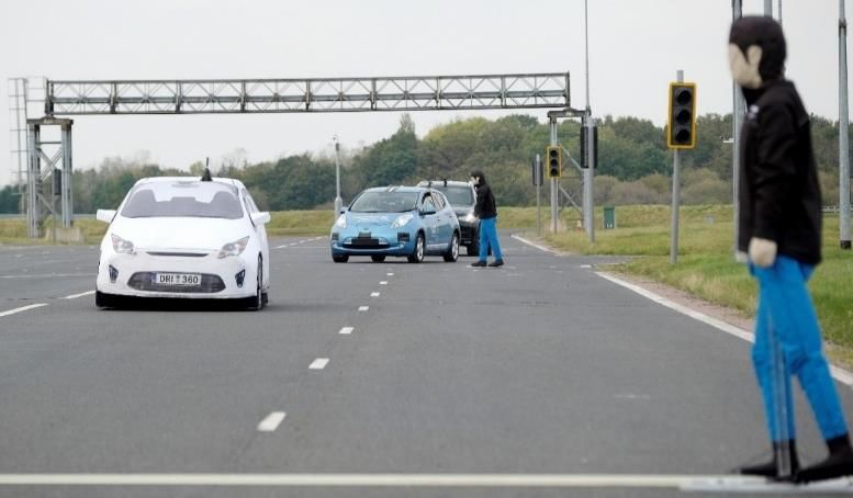
HumanDrive
Test Methods for Interrogating Autonomous Vehicle Behaviour

Executive Summary
HumanDrive is a collaborative R&D project, part funded by innovate UK, that is developing an autonomous
vehicle (AV) that uses artificial intelligence and deep learning to enable more humanistic driving behaviour
than that typically associated with AV prototypes. The culmination of the project was a ‘Grand Drive’ of
over 200 miles, incorporating a range of challenging road types. The project is led by Nissan, with a neural
network-based control system being provided by Hitachi, and other consortium members conducting
research on what constitutes ‘humanistic’ driving behaviour and on the effect of such automation on the
transport network.

HORIBA MIRA is a member of the consortium, providing facilities and support for dynamic testing upon
the HORIBA MIRA proving ground and supporting the safety work package (led by the Connected Places
Catapult). This report focusses upon methodologies for integrating the topics of safety and testing such
that the behaviour of the AV can be interrogated sufficiently to provide safety assurance, and proposes
the use of ‘Scenario Based Testing’, as opposed to extended-mileage uncontrolled validation testing, as a
more viable way to expose the system to a sufficient range of challenges.

In order to derive the test cases, HORIBA MIRA developed a process to develop scenarios from a high level
of abstraction to a lower level of abstraction. This process starts with an examination of the use cases for
the system, in order to identify the underlying functions that the system is required to be capable of
performing (such as maintaining a driving path within the lane boundaries, responding to traffic lights,
detecting other vehicles etc). A set of high-level ‘Functional Scenarios’ are then designed such that the
complete set exercises each required function in a range of permutations representative of the
Operational Design Domain of the system.

The parameters that can be varied within each Functional Scenario are identified, together with their
possible ranges, to create ‘Logical Scenarios’. Multiple ‘Concrete Scenarios’ are then created from each
Logical Scenario by selecting suitable combinations of parameters such that a representative sample of
the possible permutations is taken. Finally, Concrete Scenarios are converted into Test Cases through the
addition of logistical information and success criteria.

In order to select suitable combinations of parameters for Concrete Scenarios from the available ranges
within the Logical Scenarios, an approach was developed where each parameter range was divided into
multiple sub-ranges (‘levels’) and a pairwise matrix was used to select test points such that each possible
combination of levels for any pair of parameters was included in the Concrete Scenarios. A fractional
factorial approach such as this was needed as it would be impractical to perform a full factorial study, i.e.
to test every possible combination. The selected test points were then randomised within the sub-range
provided by its given level to ensure a good spread of values was provided for each parameter. This report
describes this novel approach, dubbed ‘Fuzzed Pairwise Testing’, examines how it can be extrapolated to
other forms of orthogonal array beyond pairwise arrays, and compares it with another multi-dimensional
sampling method, Latin Hypercube Sampling with Multi-Dimensional Uniformity.

This report also recommends methods to make scenario-based testing more effective and more efficient,
such as the need for a repository to capture information on what parameters should be tested for a given
Operational Design Domain and what the acceptance criteria should be, to ensure that the test scenarios
include a range of permutations equivalent to millions or billions of miles of real-world driving. This would
reduce the likelihood of permutations that trigger system errors remaining undiscovered until the system
is deployed. Furthermore, the use of ‘sequential testing’ methodologies to provide a statistical basis for
early termination of testing if the performance is suitably far above or below the acceptance threshold is
proposed; given the volume of testing required for AVs, this approach could result in significant savings.

HORIBA MIRA |March 2020                                                                                    2
HumanDrive
Test Methods for Interrogating Autonomous Vehicle Behaviour

Contents
Executive Summary ............................................................................................................................ 2
Contents ............................................................................................................................................ 3
1.    Introduction ................................................................................................................................ 4
     1.1      Project Description ......................................................................................................................... 4
     1.2      Complexity of Control Systems ...................................................................................................... 5
     1.3      The role of Safety Processes ........................................................................................................... 6
2.    Development of Test Cases .......................................................................................................... 8
     2.1      Scenario-Based Testing Overview .................................................................................................. 8
     2.2      How the Process was Applied ........................................................................................................ 9
     2.3      Functional Scenarios....................................................................................................................... 9
     2.4      Logical Scenarios...........................................................................................................................11
     2.5      Concrete Scenarios .......................................................................................................................12
3.    Wider Considerations for Future Testing .................................................................................... 16
     3.1      ‘Divide and Conquer’ Approach to Testing...................................................................................16
      Sub-Dividing the Problem .................................................................................................................... 16
      Testing the Perception Layer ............................................................................................................... 17
      Testing the Planning Layer ................................................................................................................... 18
      Testing the Actuation Layer ................................................................................................................. 18
      Advantages of Subdivision ................................................................................................................... 19
      Whole-Vehicle Testing and Correlation ............................................................................................... 19
     3.2      Bounded Sequential Testing .........................................................................................................21
      The Sequential Testing Concept........................................................................................................... 21
      Adding Time-Bound Aspect.................................................................................................................. 22
     3.3      Recommendation for a Test Parameter Repository.....................................................................26
      The Need for Data Sharing ................................................................................................................... 26
      How the Process would Work .............................................................................................................. 27
4.    Physical Test Capability Development ........................................................................................ 30
5.    Conclusion ................................................................................................................................ 31
6.    References ................................................................................................................................ 32
Appendix 1 – Further Analysis of Sampling Methods ......................................................................... 34
Appendix 2 – Mitigation of the Effects of ‘Peeking’ in Sequential Testing ........................................... 42

HORIBA MIRA |March 2020                                                                                                                                    3
HumanDrive
Test Methods for Interrogating Autonomous Vehicle Behaviour

1. Introduction
1.1 Project Description
                          The HumanDrive consortium consists of the organisations shown in
Table 1. The project was divided into ‘work packages’, with HORIBA MIRA supporting work packages
relating to ‘Trials, Demonstration and Validation’ and ‘Safety Management’.

                                        Organisation                          Role
                         Nissan                                        Lead

                         Atkins Ltd                                    Collaborator

                         Cranfield University                          Collaborator

                         Highways England                              Collaborator

                         Hitachi                                       Collaborator

                         HORIBA MIRA                                   Collaborator

                         SBD Automotive                                Collaborator

                         Connected Places Catapult                     Collaborator

                         Aimsun Ltd                                    Collaborator

                         University of Leeds                           Collaborator

                                   Table 1 : Organisations involved in HumanDrive

The consortium developed a prototype Autonomous Vehicle (AV) capable of achieving high levels of
automation, with the aim being to successfully demonstrate an autonomous ‘Grand Drive’ from Cranfield
to Sunderland (over 200 miles) in live traffic. This was completed in November 2019 and demonstrated
successful navigation of country roads, motorways and dual carriageways. The project commenced in July
2017 and runs for a duration of 33 months, finishing at the end of March 2020.
One of the major innovative aspects of HumanDrive is the development of an advanced control system
designed to allow the AV to emulate a natural, human-like driving style. A key enabler for this is the
integration of an Artificial Intelligence (AI) controller utilising Artificial Neural Networks (ANNs) and deep
learning for perception and decision-making.
In addition to learning from HumanDrive, this report also draws upon the knowledge gained within the
SAVVY project, as there was significant cross-pollination of ideas between HORIBA MIRA’s contributions
to the two projects. SAVVY is a collaboration between AVL (lead partner), WMG, Vertizan, HORIBA MIRA
and Myrtle, and like HumanDrive is also in receipt of funding from Innovate UK in line with the strategic
objectives laid out by the Centre for Connected and Autonomous Vehicles (CCAV). The aim of the project
was to develop a lane centering system for a passenger vehicle in order to serve as a case study for
developing advanced processes for Model-Based Systems Engineering, simulation testing and physical test
case development. HORIBA MIRA therefore gratefully acknowledge the support of AVL, WMG, Vertizan
and Myrtle in addition to the support of the HumanDrive consortium.

HORIBA MIRA |March 2020                                                                                     4
HumanDrive
Test Methods for Interrogating Autonomous Vehicle Behaviour

1.2 Complexity of Control Systems
The use of AI within the perception layer of prototype AVs and production driver assistance systems (e.g.
Autonomous Emergency Braking, Traffic Sign Recognition) is well established. This is due to the proven
ability of Convolutional Neural Networks (CNNs), a sub-category of ANNs particularly suited to vision
systems, to perform complex classification tasks effectively.
Hitachi are developing their own CNN-based perception system, including a number of innovations that
are subject to patent submissions, but perhaps the most innovative aspect of the vehicle is the use of ANNs
for decision making (i.e. deciding what manoeuvre to make and when) and path planning (i.e. defining the
exact trajectory to be used for that manoeuvre). The use of ANNs within an AV’s control system presents
a significant challenge, as it is not possible to infer any human-understandable meaning from the weights
assigned to nodes within an ANN. The system therefore has to be tested as a ‘black box’, as it is not possible
to apply ‘white box’ test methods that specifically target the inner workings of the system.
However, this problem of testing a system that is not fully understood is not restricted to ANN-based
control systems. Even when using a traditional algorithmic approach for the control system, the extreme
complexity of both the control system and the environment that it is deployed within mean that the
behaviour may not be able to be understood as a white box, and may therefore have to be tested as a
black box, or potentially a grey box (where the inner workings are partially understood).
Furthermore, such complexity may blur the lines between deterministic systems (where the response to
the same input is always identical) and non-deterministic systems (where the response varies according
to time history, further learning undertaken, pseudo-random numbers affecting decisions etc.). For
example, the smallest variation such as a bird flying past could affect the response of the vehicle in two
otherwise identical test runs; if the presence and exact position of that bird is not logged within the test
data, a deterministic system would appear to be behaving non-deterministically to anyone analysing the
results. Note that ANNs and algorithmic systems can be either deterministic or non-deterministic, even
though the term deterministic is often erroneously used to mean algorithmic (as opposed to ANN-based)
systems.
HORIBA MIRA propose the terms ‘interrogable’ and ‘uninterrogable’ to capture whether it is possible in
practice to fully understand the system behaviour such that outputs can be mapped to inputs. This
overcomes the ambiguity caused by white boxes being so complex that they effectively become black
boxes (especially to industry regulators who may not have access or the ability to analyse all details of the
internal workings), deterministic systems and their environment being so complex that they appear non-
deterministic, and the term deterministic commonly being mis-applied.
Whilst in theory it is possible to decode the inner workings of even the most complex systems in the most
complex environments, given enough testing and analysis, in practice the number of patterns needing to
be decoded increases exponentially with the number of parameters acting as inputs to the system.
Therefore, it is expected that all AV control systems will be found to be uninterrogable in practice.
However, even if it is impossible to fully understand the relationship between inputs and outputs, this
report argues that it is possible, albeit very challenging, to develop a test programme that samples enough
points within the range of scenario permutations to provide acceptable confidence that system errors will
be sufficiently rare to allow deployment.

HORIBA MIRA |March 2020                                                                                     5

HumanDrive
Test Methods for Interrogating Autonomous Vehicle Behaviour

Validating updates to autonomous systems poses a challenge due to the limited interrogability. Whereas
for a rules-based system it would be possible to undertake a limited suite of ‘regression tests’ following
system updates, to confirm that the intended behaviour has been introduced without adding any
unwanted ‘emergent behaviours’, in the case of ANNs it is impossible to draw any inferences about how
far-reaching the change to the output could be. Even adding a single extra sample to the training set could
cause behaviours to change in completely unexpected ways.
The need to validate the safety of AI-based behaviour and control subsystems can be partially mitigated
by providing an algorithmic system as a ‘safety cage’ that is able to over-rule the AI when it determines an
output is hazardous; this potentially makes testing easier as safety becomes dependent upon a more
traditional system. However, there are two major limitations that will prevent this approach from being a
complete solution that removes the need to validate the AI:
    1. The ‘safety cage’ would need to allow a wide enough tolerance to ensure the AI is driving the
       vehicle under normal circumstances, but a narrow enough tolerance to ensure it intervenes when
       required, with these requirements not necessarily being compatible. For example, setting the
       maximum lateral acceleration allowed by the safety cage too high would mean that the safety
       cage would provide no protection in low grip conditions, but setting it too low would mean
       excessive intervention in high grip conditions. Taken to an extreme, an overly restrictive tolerance
       would cause the safety cage to intervene so frequently that it effectively becomes the main control
       system;
    2. The safety cage would need to understand what constitutes acceptable behaviour in a vast range
       of scenarios. Analysis of the various permutations available in even a simple scenario (e.g. pulling
       out from a T junction) will quickly reveal the enormity of the task in trying to define what
       constitutes acceptable behaviour exhaustively. The safety cage would therefore have to assume a
       level of complexity not dissimilar to the AI, making it challenging (if not impossible) to program
       and making it uninterrogable (therefore similarly challenging to test as the AI).
Furthermore, a safety cage would not provide any protection against mistakes made by the perception
subsystem. The use of an algorithmic safety cage is therefore not seen as a complete solution, and testing
will also have to be undertaken to demonstrate the safety of the AI itself.

1.3 The role of Safety Processes
Typical safety cases for production Advanced Driver Assistance Systems (ADAS) are currently based upon
compliance with ISO 26262 (Functional Safety, i.e. ensuring the system is safe with regard to faults within
the system) and ISO PAS 21448 (Safety of the Intended Function, or SOTIF, i.e. ensuring that the inherent
system weaknesses and functional insufficiencies have been addressed sufficiently such that the system is
safe when operating as designed).
The challenge of achieving functional safety, although significant due to the complexity of AVs and the
high level of safety integrity required, is not fundamentally different to the challenges faced in applying
ISO 26262 to current ADAS systems. As such, existing functional safety processes are broadly compatible
with AV’s, albeit with the state of the art needing to be developed in some areas, such as:
    •   the need for a risk matrix approach that does not depend upon controllability by a driver;
    •   the need to agree upon a means to demonstrate ANN robustness against faults, and;

HORIBA MIRA |March 2020                                                                                   6
HumanDrive
Test Methods for Interrogating Autonomous Vehicle Behaviour
• the need to develop approaches to ‘tool qualification’ that will allow validation of highly complex
new tools for simulation and for AI training.
Indeed, it may be the case that a tool is never ‘qualified’ in its entirety, with use being conditional on
validation within the specific use cases and ranges of parameter values required, further validation being
needed before the tool can be relied upon outside the previously-validated envelope.
SOTIF is arguably the more challenging aspect for AV’s; indeed, ISO PAS 21448 is specifically limited to
systems of SAE level 2 or lower, so further development will be needed to allow application to higher SAE
levels. The extreme complexity of both AVs and their Operational Design Domains (ODDs) means that
understanding the full range of functionality required for safe operation becomes an intractable task.
There will always be residual risk due to error-triggering scenarios that are yet to be identified, and also
due to scenarios have been identified as capable of triggering errors but deemed acceptable due to low
exposure and due to the technical difficulty and cost of eliminating the risk altogether.
SOTIF requires extensive test data to be collected to reach a level of statistical confidence that the number
of hazards that remain undiscovered is acceptably low and that the assumptions made about the
acceptability of known residual risk are accurate. This report directly supports both these goals by
presenting methods to make comprehensive interrogation of the vehicle’s functionality feasible and
methods to collect and share data on what scenario permutations an AV will need to be able to respond
to within a given ODD.
It is tempting to think that such testing primarily serves to ensure SOTIF, which is understandable given
that trials of AV prototypes typically require far more safety driver interventions due to SOTIF issues than
due to failures (i.e. Functional Safety issues). However, it must be borne in mind that for AV prototypes to
approach a level of robustness appropriate for commercial deployment, the frequency of errors would
have to be exceptionally low. As such, it must be presumed that that the number of SOTIF-related issues
would be of a similar magnitude to the frequency of functional safety-related issues in current production
vehicles. As such, the test processes discussed here should not be seen as exclusively testing SOTIF, as the
testing will also be capable of uncovering Functional Safety issues such as software bugs and hardware
malfunctions that are only exposed in particular scenario permutations.
HORIBA MIRA |March 2020 7HumanDrive Test Methods for Interrogating Autonomous Vehicle Behaviour 2. Development of Test Cases 2.1 Scenario-Based Testing Overview One method of validating an AV involves accumulating large mileages with the expectation that the system will randomly encounter a representative range of scenarios, thereby providing acceptable confidence that the system would perform safely when a fleet is subjected to a far larger total mileage in service. Performance metrics such as frequency of fatalities, injuries, accident damage, near misses or traffic rule violations can be used as a proxy for the overall safety, allowing comparison to minimum acceptable levels to be made, but it has been shown (RAND, 2016) that extremely high test mileages would be required to demonstrate an autonomous system is safer than existing manually driven fleets. Whilst such mileage accumulation holds an appeal due to the simplicity of the concept and the level of assurance that would be provided, in practice such testing would take far too long to be feasible, even with an extensive fleet of vehicles testing concurrently, and would also be prohibitively expensive. Such an approach would be unprecedented from a regulatory perspective; existing regulations and standards focus upon ensuring due diligence is taken in the development process and upon performing a limited suite of specific tests covering the most prevalent accident types recorded, not upon demonstrating acceptable accident rates in extended real-life testing prior to commercial deployment. It is not feasible to accumulate sufficient real-world safety data for a pre-deployment transport system to allow a statistically valid comparison to be made with other transport systems, which is why this metric has never been used for regulatory approval in any transport sector. An alternative acceptance method for AVs is to identify a representative set of parameters defining scenarios (e.g. lane width, corner radius, weather, behaviour of other vehicles), and the ranges within which the parameters can be varied, to put together a test programme that provides coverage of every permutation. This has the potential to expose the system to the same breadth of scenarios, but with reduced mileage as the test volume would not be skewed towards repetitive and uneventful driving in non-challenging scenarios. This approach is referred to as ‘Scenario-Based Testing’ (Daimler et al, 2019). Care must be taken when attempting to use results from scenario-based testing to infer accident rates. For example, a system that performs poorly in common use cases but well in rare edge cases would be rated disproportionately favourably if test scenarios were evenly distributed, but may be found to produce unacceptable accident rates in service, where the balance of scenarios would be strongly skewed to the more common use cases. This limitation can be mitigated by adopting a hybrid approach where there is a partial bias towards the distribution in the real world, i.e. ‘normal’ scenarios would be more densely sampled, but not as densely as they would be if the balance was the same as real life (Koopman, 2019). It is likely that regulators will require some form of physical testing for validation of the system itself, as opposed to the simulation, although this is an area where there is considerable uncertainty and debate at the current time (Law Commission, 2019). However, it is anticipated that the bulk of scenarios would be performed in simulation, thereby allowing a wider range of permutations to be tested than is physically possible upon a proving ground, whilst also allowing significant reductions in time and cost. Physical testing would be used to validate the simulation across a wide range of scenario permutations and to provide an overcheck that the complete vehicle can demonstrate basic competencies in the real world when all subsystems have been integrated. HORIBA MIRA |March 2020 8
HumanDrive
Test Methods for Interrogating Autonomous Vehicle Behaviour

2.2 How the Process was Applied
To facilitate effective scenario-based testing, HORIBA MIRA developed a methodology that takes as an
input the use cases and/or high-level requirements for the system, and outputs test cases. This
methodology draws upon the terminology that was developed within the PEGASUS Project (2017), and
uses three ‘levels’ of scenario, progressively developed to incorporate more specific detail. This is
summarised in Figure 1 and described in the following subsections.

    Figure 1: Summary of the three levels of scenarios used to generate test cases from the system's use cases

Throughout the process, there must be full traceability to the previous stage (e.g. logical scenarios must
be traceable to functional scenarios). Furthermore, it must be ensured that the final test cases and their
pass criteria provide full coverage of the requirements for the system, including safety and performance
requirements. This results in a complex matrix of test cases, as illustrated in Figure 2; every possible
combination of system behavioural requirements and surrounding environment permutations (as defined
by the ODD) is a possible scenario, resulting in a multi-dimensional ‘problem space’ to investigate.

2.3 Functional Scenarios
Functional scenarios use natural language and/or simple illustrations to provide a high-level description of
the scenario being performed. This includes the road layout involved, and the manoeuvres being
performed by the AV and by other actors. Every requirement for the system must covered by at least one
functional scenario – requirements may be covered by more than one functional scenario, and a functional
scenario may cover more than one requirement, but there should be no requirements that go uncovered,
and no scenarios that are not linked to the requirements. Note that in line with established systems
engineering practice, it would be expected that the requirements deck provides full coverage of every step
of every use case, including alternate flows, and therefore full coverage of the requirements should be
taken to indicate full coverage of the use cases.

HORIBA MIRA |March 2020                                                                                          9
HumanDrive
Test Methods for Interrogating Autonomous Vehicle Behaviour
Figure 2: Complex matrix of test parameters resulting from the need for testing to cover behavioural requirements
and environmental requirement
Figure 3: Examples of functional scenarios
HORIBA MIRA |March 2020 10HumanDrive
Test Methods for Interrogating Autonomous Vehicle Behaviour
Figure 3 illustrates two Functional Scenarios derived from the HumanDrive use cases, with a diagram to
illustrate the scenario, a list of functions that the AV must perform within the scenario, and the expected
behaviour (in the case of these scenarios, there are two allowable responses, a and b). This format was
found to provide a good basis for discussion with other stakeholders.
2.4 Logical Scenarios
The Logical Scenarios represent an intermediate step to get from Functional to Concrete Scenarios. The
aim of the logical scenarios is to identify all the parameters that could affect the behaviour of the vehicle,
including the ranges that they could vary within, in preparation for selecting specific points within these
ranges to create Concrete Scenarios. HORIBA MIRA developed an approach for this where ‘known
parameters’ (i.e. those that engineers are aware of and incorporate within the test design) are separated
into two categories:
1. Intended Parameters – these are parameters where it is intended that the AV will change its
behaviour in response to changes to the parameter value. For example, in UC08_06 (Figure 3), the
AV is legally permitted to cross the solid white lines to overtake the cyclist if the cyclist is travelling
at 10mph or less, but must not cross the white line otherwise. Speed is therefore an intended
parameter, as is lane marking type;
2. Unintended Parameters – these are parameters that are not intended to influence the AV
behaviour, but could reasonably be expected to. An example of this would be degraded lane
markings in UC08_06, which ideally would have no effect, but in practice may cause the system to
misclassify the line as being broken, resulting in a change in behaviour.
In addition to this, Unknown Parameters are parameters that either hadn’t been identified as a possible
variable (unknown unknowns, a problem that chapter 3.3 seeks to address), or that have been identified
but hadn’t been suspected to be capable of affecting vehicle behaviour. If any of the unknown parameters
are discovered (i.e. become known parameters) in the course of testing, and the logical scenarios, concrete
scenarios and test cases will need to be updated accordingly.
Two logical scenarios from the project are shown in Figure 4, where intended and unintended parameters
can be seen, subdivided according to whether they are an attribute of the road layout, a static obstacle, a
dynamic obstacle or part of the environment. Some parameters have a continuous range specified,
whereas others have discrete variables (e.g. the type of target car is limited to two specific soft target
vehicle types). Parameter values marked with a ‘?’ denote that the ability to control the range is limited
(e.g. where it will be defined by the pre-existing road characteristics at that point). A production system
will require more exhaustive testing, so it will be necessary to investigate the effect of varying these
parameters, requiring the use of simulation and/or a highly configurable test bed.
HORIBA MIRA |March 2020 11HumanDrive
Test Methods for Interrogating Autonomous Vehicle Behaviour
Logical Scenario ID 08_02 08_06
Summary Approach and overtake static car Approach and overtake longitudinal cyclist, solid white lines
Intended Parameters Range Unintended Parameters Range Intended Parameters Range Unintended Parameters Range
Road Layout Prevailing speed limit 30-60 mph Lane width ? Prevailing speed limit 30-60 mph Lane width ?
Curvature ? Curvature ?
Camber ? Camber ?
Gradient ? Gradient ?
Lane marking condition norm/worn
Static Obstacles Type of car GST, EVT
Lateral offset of POV lane limits
Dynamic Obstacles Speed of cyclist 0-20 mph Lateral offset of cyclist lane limits
Environment As measured during test As measured during test
Expected Behaviour Stay in lane Stay in lane
Overtake static actor Overtake dynamic actor if cyclist speed 10mph
Illustration
Functions Exercised Detect unintended obstruction Detect unintended obstruction
Detect Cars Detect cyclists
Detect lane boundaries Detect lane boundaries
Figure 4: Two Logical Scenarios from HumanDrive
2.5 Concrete Scenarios
The next stage is to select specific points within the available range for each parameter in order to generate
concrete scenarios. To ensure coverage of the possible permutations, it is necessary for each logical
scenario to result in multiple concrete scenarios; it is not possible to understand how the system reacts to
the parameters unless they are varied. As multiple parameters are being changed, rather than a single
independent variable, the problem lends itself to a factorial experiment design approach.
By quantising continuous variables into discrete ‘levels’ within their available ranges (so that the number
of levels remains finite), a ‘full factorial’ approach could be used where every combination of possible
values is tested. However, the number of test cases rapidly escalates as the number of factors to be
investigated increases, making this exhaustive approach impractical.
It is therefore necessary to take a ‘fractional factorial’ approach, where not every combination of
parameter levels is tested, but the combinations chosen are suitably dispersed throughout the problem
space such that good coverage is still obtained. Using such an approach can result in drastic reductions in
the time and cost of testing, with minimal reduction in the quality of the results. The approach used within
the HumanDrive scenario development process was derived from a method called ‘pairwise testing’.
The use of pairwise testing within software verification has become well established as a means to capture
the most prevalent defects efficiently. The matrix of test cases forms a ‘2nd order orthogonal array’ where
parameters are not just investigated in isolation (1st order effects), but also each possible pair of
parameters is fully investigated (Software Testing Help, 2019).
HORIBA MIRA |March 2020 12HumanDrive
Test Methods for Interrogating Autonomous Vehicle Behaviour
A simple example of a second order effect is that a system may function as intended on all bend radii that
are within the ODD if just tested at a medium speed, and at all speeds if just tested on a medium radius
bend. However, if the two parameters are investigated together, it is entirely plausible that performance
would degrade when testing at higher speeds on lower radius (i.e. tighter) bends. This is therefore a 2nd
order effect, as neither parameter can cause a requirement to be violated in isolation, but two parameters
being varied together can result in permutations that cause a requirement to be violated.
Higher order effects are not covered, so if three or more parameters have to be at certain combinations
of values for a fault to occur, there is no guarantee that the fault will be found; it is possible that the critical
combination of parameters may be included by chance, but not certain. This was deemed appropriate due
to the limited timescale and budget, as interrogating higher order effects would have resulted in
significantly more test cases. Another measure taken to control the number of test cases was limiting each
parameter to three levels within the available range (low, medium and high). For a production AV test
program where a safety driver is not available as an additional layer of protection, it is expected that far
more test cases would be undertaken to ensure satisfactory coverage of the problem space, with higher
order effects being interrogated and each parameter quantised into more intervals. It is also envisaged
that far more parameters would need to be investigated than was feasible within an R&D trial.
Figure 5: Test cases required using a pairwise approach if 4 parameters are investigated, each having 3 levels.
Shown in table and graphical from
Figure 5 shows a 4 x 3 pairwise matrix, i.e. there are four parameters, each of which are able to assume
three levels. These levels are low, medium and high for the first three parameters, but blue, purple and
red have been used for the fourth parameter (the use of colours allowing illustration on three-dimensional
axes). Choosing any two of the four parameters, it can easily be confirmed that each possible combination
of levels for that pair is present, meaning that 2nd order effects are covered. The sampling of the problem
space is illustrated on the right of the figure.
Note the good spacing of parameters; each plane has three test cases, and wherever there appears to be
a gap (e.g. top-left of the front face), there are other test cases nearby (in this case, in the middle of all
three planes adjoining the top left point). The result could, however, be criticised for over-representing
HORIBA MIRA |March 2020 13HumanDrive
Test Methods for Interrogating Autonomous Vehicle Behaviour
extreme values, with no points in the centre, whereas in real-world driving parameters will tend to be
biased to medium values. This issue is addressed later.
For comparison, Figure 6 shows the number of test cases that would be required if using a full factorial
approach. Bearing in mind that each ‘ball’ has to be tested three times (to cover each colour representing
parameter 4), 81 test cases would be required, which would have been unfeasible within the HumanDrive
project.
Figure 6: Illustration of the number of test cases (81) that would be required using a full factorial approach for the
same problem - note that each 'ball' has 3 colours, representing 3 test cases
Prior to the application of pairwise arrays, an attempt was made to parameterise a number of Logical
Scenarios by simply using judgement to attain good coverage. A retrospective comparison of the two
processes was interesting; plotting both upon three-dimensional axes, it was immediately apparent that
the pairwise approach resulted in a much better spread of points for sampling, and therefore better
coverage of the problem space. In contrast, manual selection of parameters, despite the intention to
achieve a good spread, resulted in some areas being sampled more densely at the expense of other areas
not being sampled at all. Furthermore, manually selecting parameters is not scalable, preventing
automation of large test programmes.
The final stage in selecting the values was to introduce randomisation within the levels defined for low,
medium and high for each parameter. This allows a wider range of possible values for each parameter to
be covered; otherwise, parameters would only be tested at maximum, minimum in mid-point values, with
multiple repeats of these values and no coverage of the possible sub-ranges in between.
The approach also has the advantage that it makes it more difficult to optimise a system to the test as it is
not possible to predict exact parameter values that will be chosen by the randomisation. Further
unpredictability can be added by randomising which parameter from the logical scenarios is assigned to
which column in the pairwise matrix.
Because of this randomisation, the approach developed for the project has been dubbed ‘fuzzed pairwise’
testing, as there is more flexibility in the values adopted relative to a strict application of the pairwise
HORIBA MIRA |March 2020 14HumanDrive
Test Methods for Interrogating Autonomous Vehicle Behaviour
approach. More generally, this report proposes the term ‘fuzzed orthogonal array’ to cover arrays that
include higher orders than pairwise arrays.
Other parameters that were not included within the orthogonal array should then be assigned values
randomly. Note that in some cases, the selection will be outside the control of the testing organisation,
e.g. colour of another vehicle may be dictated by the availability of a suitable soft target dummy vehicle
for physical testing.
A summary of the ‘loose orthogonal array testing’ approach developed for the project is as follows:
1. Select the highest-priority parameters (i.e. those that warrant the most detailed investigation) –
this will be the ‘intended parameters’ and ‘unintended parameters’;
2. Divide each parameter range for a logical scenario into multiple ‘levels’ (e.g. low, med, high) – the
more levels selected, the more tests will be required, so this can be used to control the volume of
testing;
3. Identify suitable orthogonal array type for the number of variables and levels (e.g. pairwise
matrix), and generate the matrix – again, the array selection can control the volume of testing, as
covering higher order effects will require more samples;
4. Map the parameters onto the matrix (e.g. assign road width to the first column, oncoming vehicle
speed to the second column etc.);
5. Optionally, include additional centre point if not already present, to improve representation of
non-extreme values;
6. Randomise independent variables to points within the subrange determined for that level
o e.g. if ‘low’ is less than 15mph, variable could assume any value from 0 to 15mph;
7. Randomise the noise factors not suspected capable of having an effect;
o It may be preferable to include a bias towards values that are more prevalent in real-life;
o Some noise factors may not be controlled due to practical limitations, e.g. weather;
8. Eliminate or modify any test points that are not feasible (impossible combinations, facility
limitations). Any resulting ‘gaps’ need to be reviewed, and mitigated if possible (e.g. testing similar
functionality in other scenario permutations, testing in simulation rather than physical world)
Pairwise testing is a well-established and popular approach to software testing, where experience has
shown that the majority of defects are 1st or 2nd order, making searching for higher-order effects inefficient.
However, bearing in mind the complexity and the safety-critical nature of approving production AVs where
a safety driver would not be available, searching for higher order effects would be justified.
The number of orders needing to be investigated can only be determined empirically, based on experience
of how many higher-order effects are found. This therefore requires testing in the early years of CAV
development to be conservative and search more orders than may be necessary, until data exists to justify
being able to reduce the test volume. Further consideration of how to optimise the sampling of the
problem space, including the use of higher-order orthogonal arrays and of alternative methods such as
Latin Hypercubes, is included within Appendix 1.
The final stage in the test case development process is to assign each concrete scenario to specific locations
and specific test apparatus, and to include success criteria. As full traceability should be maintained
throughout the process, it will be possible to directly infer the acceptance criteria from the requirements.
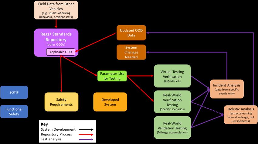
HORIBA MIRA |March 2020 15HumanDrive Test Methods for Interrogating Autonomous Vehicle Behaviour 3. Wider Considerations for Future Testing 3.1 ‘Divide and Conquer’ Approach to Testing Sub-Dividing the Problem Enhanced test efficiency could be gained by applying a ‘divide and conquer’ approach to validating AVs, such that the type of testing selected (e.g. software-in-the-loop, proving ground verification) is chosen to be most appropriate for the particular layer of the AV control system that is under test (e.g. perception layer, actuation layer). Each layer would primarily be tested in isolation, although integration testing would also be needed to provide assurance that there are no adverse effects introduced when the layers are combined. A summary of the approach can be seen in Figure 7. Figure 7: Relative merits of different test formats, mapped against different layers within the AV control system For maximum control of the inputs presented to that layer, it would be preferable to be able to tap directly into the data being passed between layers at the interfaces. However, it would also be possible to set up scenarios up that are designed to work with the whole stack as an integrated system whilst specifically targeting the functionality of one layer, e.g. by providing inputs to the perception layer that are simple enough that the signal passed to the planning layer is predictable. Working with the full system in this way would introduce some error from other layers (for example, the perception layer may not estimate relative distances or speeds with perfect accuracy). The ‘divide and conquer’ approach advocated here should be seen as consistent with, and building upon, the approach advocated by Amersbach and Winner (2019). HORIBA MIRA |March 2020 16
HumanDrive
Test Methods for Interrogating Autonomous Vehicle Behaviour

Testing the Perception Layer
For the perception layer of the control system, realism of the inputs to sensors is crucial, and this is a
significant concern with software-in-the-loop testing (SIL) as the accuracy is dependent upon models of
both the physical environment (including permutations such as fog and rain, which are challenging to
simulate accurately) and the sensors. Beyond the fundamental challenge of simulating the physics of a
sensor, there would be limited incentive for a Tier 1 supplier to want to incorporate the limitations of their
product into any model they create, and questions as to how well a neutral 3rd party will be able to
understand the inner workings of the sensor. This means that the accuracy of sensor simulation can never
be assumed to be perfect.
Simulation testing can incorporate various different levels of hardware, referred to as ‘hardware-in-the-
loop’ (HIL) testing’. The ultimate level of hardware possible to incorporate into a simulation is ‘vehicle-in-
the-loop’ (VIL) testing, shown in the second column of Figure 7, where an entire vehicle is subjected to
testing in the virtual world. Testing with real sensors receiving a simulated input removes concerns about
the realism of the sensor simulation, but at the cost of needing to develop and validate the ability to spoof
sensors using simulated inputs.
In practice, there is a continuum from pure SIL testing to full VIL testing, with variation in the amount of
hardware elements included in the loop and also the maturity of those elements (i.e. how representative
of the production version they are). For clarity, Figure 7 shows just the two extremes of the continuum, but
it is anticipated that production test programs would incorporate progressively more hardware elements
as they become available and the task of integrating the subsystems progresses.
Ultimately, it is impossible to achieve perfect realism in a virtual world, and it will therefore be necessary
to include extensive real-world testing of the perception layer within the test programme. Evidence of
acceptable performance can be gained through scenario-based verification testing on a proving ground
(column 3) or through extended-mileage validation on public roads (column 4), but in many cases the most
convenient and lowest-cost option will be to perform open loop testing (column 5). This could involve
either manually driving the AV with the system performing perception tasks in the background, or using a
manual vehicle fitted with the same sensor suite as the AV to collect data to use in post-processing. The
data collected would also have value in helping to identify new edge cases to include in the scenario-based
testing (i.e. uncovering ‘unknown unknowns’).
Labelling data to form that ground truth to assess perception systems against will be a significant
challenge. This could require the development and validation of an automated process or require
extensive manual work, but perhaps a more feasible approach would be a hybrid solution where human
oversight is used when the automated process has low confidence or when it produces a different result
to the AV perception layer under test. It is worth noting that open loop testing in the real world would also
typically be used to collect training data for a CNN used to classify objects within the perception layer. As
the training and testing process for the CNN would normally be iterative, much of the data collected from
the sensors during open loop testing would also be suitable to use as training data for future iterations.
As it will not be possible to cover all scenario permutations in all test environments, it may be necessary
to cover some challenges to the perception layer solely in the virtual world and others solely in the physical
world. Scenarios that can be performed in both real life and in simulation would allow validation of the
simulation to enhance confidence in the accuracy of results of all simulations.

HORIBA MIRA |March 2020                                                                                    17
HumanDrive
Test Methods for Interrogating Autonomous Vehicle Behaviour

Testing the Planning Layer
The ‘planning’ layer of the AV control system incorporates such functionality as deciding what manoeuvres
the vehicle should undertake (e.g. go/no-go decisions on performing a lane change or pulling out from a
junction) and the planning of a suitable trajectory and speed profile for the manoeuvre. Depending on the
architecture of a particular AV, these functionalities may be provided by a single subsystem or multiple
subsystems, the latter being able to be tested as a whole or further ‘divided and conquered’.
Simulation is the most effective option for testing the planning layer as it allows an infinite range of
scenarios to be tested, including geometries that cannot be found on a proving ground. In addition,
simulation testing can be done at significantly lower cost and in less time that physical testing.
Being sandwiched between the perception and actuation layers, the planning layer is isolated from the
physical world, meaning that inaccuracies within physics models do not come into play. For example, a set
of inputs to the planning layer (e.g. some form of map with an occupancy grid to show the location of
dynamic obstacles) in the virtual domain would be indistinguishable from the same set of inputs received
in response to sensor outputs in the real world. As such, simulation testing of the planning layer can be far
less computationally intensive than simulation of layers that require the complex physics of the real world
to be replicated.
On the other hand, VIL testing of the planning system is a less favourable option, as testing the planning
layer in isolation while the full vehicle is sat in a VIL rig makes little economic sense. However, simulation
testing should use the actual processing hardware from the planning layer where possible (i.e. HIL testing
rather than SIL testing). This will avoid inaccuracy due to hardware limitations (e.g. latency), and will also
allow some validation of the hardware (albeit in laboratory conditions – testing in more extreme conditions
would be needed to demonstrate production-level robustness). A typical approach would be to start off
with SIL, and then progressively add hardware as representative subsystems become available.
Physical testing for the planning layer has similar limitations to that discussed for VIL, with a higher cost
and less ability to control the inputs to the planning layer relative to SIL. In the case of physical testing, the
range of possible scenarios will also be limited as not all scenarios will be able to be physically recreated
using available facilities and without compromising safety.
Open loop testing of the system, with a manual driver on public roads, is also an option, as the system can
run in the background, outputting the intended path at each timestep. This has the same disadvantage as
extended-mileage validation in that it is difficult to control what inputs are received, resulting in many
miles of repetitive and uninteresting data. Furthermore, it would not be possible to see how scenarios
unfold over time as the open loop system has no control over where the vehicle will be at the next time
step, and will therefore have to keep recalculating paths from a hypothetical position that it may never
have found itself in if operating autonomously. It would therefore be difficult to evaluate how the system
would behave when deployed.

Testing the Actuation Layer
For the actuation layer of the AV control system, simulation has significant limitations as the path adopted
by the vehicle will depend upon the accuracy of the vehicle dynamics model and the models of the
actuators controlling steering, braking and acceleration. There is likely to be value in using simulation early
in the development process to set an initial baseline for the low-level control algorithms quickly and
cheaply, which can then be refined, calibrated and later verified by physical testing. It is worth noting that

HORIBA MIRA |March 2020                                                                                        18
HumanDrive
Test Methods for Interrogating Autonomous Vehicle Behaviour

vehicle dynamics simulation is an established field that is well supported by specialist tools, making state-
of-the-art simulation relatively accessible.
Proving ground testing has a particular advantage for the actuation layer as a wide-open area of tarmac
can be used to compare the input (the desired path sent by the planning layer) to the output (the path
actually taken). There is no need for the scene to appear realistic as the perception sensors are not
involved, so any radius of curve, for example, can be tested without the need to apply white lines, add
kerbs etc. Furthermore, proving grounds often feature challenging road geometries such as off-camber
bends, extremely high crowns on the road etc., which can validate the actuation layer’s ability to adapt to
extreme outliers.
This testing can be further supported by extended-mileage validation, which will provide a wide range of
permutations, but also feature a significant volume of repetitive and uninteresting data. As extended
mileage validation would by necessity include the entire control system, it would be necessary to record
the outputs from the previous layers in the stack, as the actuation system can only be validated by
comparing its outputs to its inputs; an undesirable path could be caused by any of the layers, and cannot
be assumed to be due to the actuation layer.
Open loop testing of the actuation layer is not possible, as the driver will be manually providing control
inputs rather than the system. However, there may be some rare exceptions to this where it is desirable
to test the low-level control algorithms in isolation, without this being connected to the actuators
themselves; this could be viewed as another level of ‘divide-and-conquer’ subdivision within the actuation
layer.

Advantages of Subdivision
There are three key advantages in subdividing testing of the system in this way:
    1. The method of testing can be optimised to the layer of the control system stack that is being
       tested, for maximum efficiency, as was shown in Figure 7.
    2. The total number of permutations that would need to be tested is much lower. For example, if
       we take a hypothetical system operating in an (extremely limited) ODD where there are 20
       different things that need to be perceived (e.g. roundabout, pedestrian), 10 different manoeuvres
       that can be performed, and 15 different paths that the actuators can be required to follow, if the
       system is tested in its entirety, the number of permutations to test is 20 x 10 x 15 = 3000. However,
       if the possible combinations for each layer are tested in isolation, the total number of tests
       required is 20 + 10 + 15 = 45, which is 1.5% of the number of test cases for whole-system testing.
    3. Less testing is required to introduce updates to the system. For example, if an update is
       introduced to the planning layer, it would be feasible to validate this purely through simulation,
       without having to repeat any of the test cases associated with the perception and actuation layers,
       provided that the interfaces between the layers remain unaltered.

Whole-Vehicle Testing and Correlation
While the ‘divide and conquer’ approach will provide a significant reduction in the overall test burden,
nonetheless it is expected that some validation testing would be undertaken using the vehicle as a whole
in a real-world environment, as this would be needed as an overcheck to ensure there are no unexpected

HORIBA MIRA |March 2020                                                                                   19
You can also read