PMC-230 Single-Phase Multifunction Meter User Manual Version: V1.1 - April 1, 2022 - cet-global.com
←
→
Page content transcription
If your browser does not render page correctly, please read the page content below
PMC-230
Single-Phase Multifunction Meter
          User Manual
          Version: V1.1
            April 1, 2022
This manual may not be reproduced in whole or in part by any means without the express written
permission from CET Electric Technology (CET).
The information contained in this Manual is believed to be accurate at the time of publication; however,
CET assumes no responsibility for any errors which may appear here and reserves the right to make
changes without notice. Please consult CET or your local representative for latest product
specifications.

                                    Standards Compliance

          DANGER
This symbol indicates the presence of danger that may result in severe injury or death and permanent
equipment damage if proper precautions are not taken during the installation, operation or
maintenance of the device.

          CAUTION
This symbol indicates the potential of personal injury or equipment damage if proper precautions are
not taken during the installation, operation or maintenance of the device.

                                                   I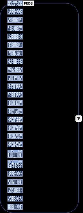
CET Electric Technology

             DANGER
    Failure to observe the following instructions may result in severe injury or death
    and/or equipment damage.
➢   Installation, operation and maintenance of the meter should only be performed by
    qualified, competent personnel that have the appropriate training and experience
    with high voltage and current devices. The meter must be installed in accordance
    with all local and national electrical codes.
➢   Ensure that all incoming AC power and other power sources are turned OFF before
    performing any work on the meter.
➢   Before connecting the meter to the power source, check the label on top of the
    meter to ensure that it is equipped with the appropriate power supply, and the
    correct voltage and current input specifications for your application.
➢   During normal operation of the meter, hazardous voltages are present on its
    terminal strips and throughout the connected potential transformers (PT) and
    current transformers (CT). PT and CT secondary circuits are capable of generating
    lethal voltages and currents with their primary circuits energized. Follow standard
    safety precautions while performing any installation or service work (i.e. removing
    PT fuses, shorting CT secondaries, …etc).
➢   Do not use the meter for primary protection functions where failure of the device
    can cause fire, injury or death. The meter should only be used for shadow protection
    if needed.
➢   Under no circumstances should the meter be connected to a power source if it is
    damaged.
➢   To prevent potential fire or shock hazard, do not expose the meter to rain or
    moisture.
➢   Setup procedures must be performed only by qualified personnel familiar with the
    instrument and its associated electrical equipment.
➢   DO NOT open the instrument under any circumstances.

                                           II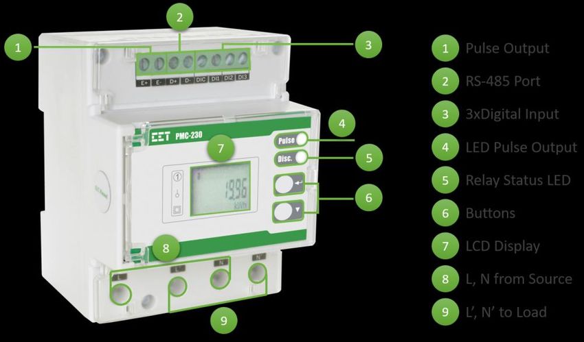
CET Electric Technology

Limited warranty
➢   CET Electric Technology (CET) offers the customer a minimum of 12-month functional
    warranty on the meter for faulty parts or workmanship from the date of dispatch from
    the distributor. This warranty is on a return to factory for repair basis.
➢   CET does not accept liability for any damage caused by meter malfunctions. CET accepts
    no responsibility for the suitability of the meter to the application for which it was
    purchased.
➢   Failure to install, set up or operate the meter according to the instructions herein will
    void the warranty.
➢   Only CET’s duly authorized representative may open your meter. The unit should only be
    opened in a fully anti-static environment. Failure to do so may damage the electronic
    components and will void the warranty.

                                             III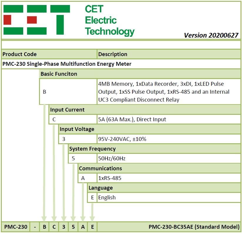
CET Electric Technology

                                   Glossary
COM / Comm.   = Communication
CT            = Current Transformer
DI / DO       = Digital Input / Output
FP            = Front Panel
Imp. / Exp.   = Import / Export
MB            = Mega Byte
MBPW          = Modbus Password
NER           = National Electricity Rules
NMI           = National Measurement Institute
PF            = Power Factor
PPS           = Pulse Per Second
RMS           = Root Mean Square
RTC           = Real-Time Clock
SCADA         = Supervisory Control And Data Acquisition
SOE           = Sequence of Events
T1 to T4      = Tariff 1 to Tariff 4
THD           = Total Harmonics Distortion
TOU           = Time of Use
UL            = Underwriters Laboratories Inc.
WAGES         = Water, Air, Gas, Electricity and Steam

                                         IV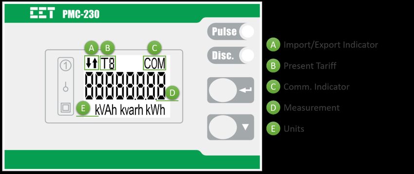
CET Electric Technology

                                                               Table of Contents
Chapter 1 Introduction ........................................................................................................................................... 1
  1.1 Overview ....................................................................................................................................................... 1
  1.2 Features ........................................................................................................................................................ 1
  1.3 PMC-230’s application in Power and Energy Management System ............................................................. 2
  1.4 Getting More Information ............................................................................................................................ 2
Chapter 2 Installation ............................................................................................................................................. 3
  2.1 Appearance ................................................................................................................................................... 3
  2.2 Terminal Dimensions .................................................................................................................................... 3
  2.3 Unit Dimensions............................................................................................................................................ 4
  2.4 Installations ................................................................................................................................................... 4
  2.5 RS-485 Wiring ............................................................................................................................................... 5
  2.6 Digital Input .................................................................................................................................................. 5
  2.7 Pulse Output ................................................................................................................................................. 5
Chapter 3 Front Panel ............................................................................................................................................. 6
  3.1 LCD Display ................................................................................................................................................... 6
    3.1.1 LED Pulse Output ................................................................................................................................... 6
    3.1.2 LCD Display Symbols .............................................................................................................................. 6
  3.2 LCD Testing .................................................................................................................................................... 6
  3.3 Display Modes............................................................................................................................................... 6
  3.4 Data Display .................................................................................................................................................. 7
  3.5 Setup Configuration via the Front Panel ....................................................................................................... 8
    3.5.1 Function of buttons ............................................................................................................................... 8
    3.5.2 Setup Menu ........................................................................................................................................... 9
    3.5.3 Configurations...................................................................................................................................... 10
Chapter 4 Applications.......................................................................................................................................... 11
  4.1 Inputs and Outputs ..................................................................................................................................... 11
    4.1.1 Digital Inputs ........................................................................................................................................ 11
    4.1.2 Energy Pulse / 1 PPS Output ................................................................................................................ 11
    4.1.3 Disconnect Relay .................................................................................................................................. 11
  4.2 Metering ..................................................................................................................................................... 11
    4.2.1 Basic Measurements ............................................................................................................................ 11
    4.2.2 Energy Measurements ......................................................................................................................... 11
    4.2.3 Demands .............................................................................................................................................. 11
    4.2.4 Harmonics ............................................................................................................................................ 12
  4.3 Logs ............................................................................................................................................................. 12
    4.3.1 Monthly Energy Log ............................................................................................................................. 12
    4.3.2 SOE Log ................................................................................................................................................ 13
    4.3.3 Data Recorder Log................................................................................................................................ 13
  4.4 Time of Use (TOU) ....................................................................................................................................... 14
Chapter 5 Modbus Map ........................................................................................................................................ 15
  5.1 Basic Measurements ................................................................................................................................... 15
  5.2 Real Time Energy Measurements ............................................................................................................... 16
  5.3 DI Pulse Counter ......................................................................................................................................... 16
  5.4 Harmonic Measurement ............................................................................................................................. 16
  5.5 Demand Measurements ............................................................................................................................. 16
    5.5.1 Present Demand .................................................................................................................................. 16
    5.5.2 Max. Demand of This Month (Since Last Reset) .................................................................................. 16
    5.5.3 Max. Demand of Last Month (Before Last Reset) ................................................................................ 17
    5.5.4 Demand Data Structure ....................................................................................................................... 17
  5.6 Logs ............................................................................................................................................................. 17
    5.6.1 Monthly Energy Log ............................................................................................................................. 17
    5.6.2 Data Recorder Log ................................................................................................................................ 17
    5.6.3 SOE Log ................................................................................................................................................ 18
  5.7 Device Setup ............................................................................................................................................... 20
    5.7.1 Basic Setup ........................................................................................................................................... 20

                                                                                    V
CET Electric Technology

    5.7.2 I/O Setup .............................................................................................................................................. 21
    5.7.3 Communication Setup ......................................................................................................................... 21
  5.8 TOU Setup ................................................................................................................................................... 21
    5.8.1 Basic ..................................................................................................................................................... 21
    5.8.2 Seasons ................................................................................................................................................ 22
    5.8.3 Daily Profile .......................................................................................................................................... 22
    5.8.4 Alternate Days...................................................................................................................................... 23
  5.9 Data Recorder Setup ................................................................................................................................... 23
  5.10 Time .......................................................................................................................................................... 24
  5.11 Remote Control ......................................................................................................................................... 25
  5.12 Clear/Reset Control................................................................................................................................... 25
  5.13 Meter Information .................................................................................................................................... 25
Appendix A – Technical Specification .................................................................................................................. 27
Appendix B – Standards of Compliance .............................................................................................................. 28
Appendix C – Ordering Guide .............................................................................................................................. 29
Contact us ............................................................................................................................................................ 30

                                                                                   VI
CET Electric Technology
Chapter 1 Introduction
This manual explains how to use the PMC-230 Single-Phase Multifunction Meter.
This chapter provides an overview of the PMC-230 meter and summarizes many of its key features.
1.1 Overview
The PMC-230 Single-Phase Multifunction Meter is CET’s latest offer for the low voltage energy metering market
featuring DIN rail mount, compact construction, 63A direct input with an internal UC3 Disconnect Relay
compliant with Australia National Electricity Rules (NER) schedule 7.5 for the ability to disconnect/re-connect
from the supply. The PMC-230 also complies with the IEC 62053-21 Class 1 kWh Accuracy Standard and has
received the certificate of approval from the National Measurement Institute (NMI) of Australia for compliance
with the M6-1 Electricity Meters, Part 1: Metrological and Technical Requirements. The PMC-230 provides 4MB
Log Memory for Data Recording, 3xDI for Status Monitoring or Pulse Counting, 1xLED Pulse Indicator and 1xSS
Pulse Output for Energy Pulsing. Further, the standard RS-485 port supporting Modbus RTU protocol with
password protection allows the PMC-230 to become a vital component of an intelligent, multifunction
monitoring solution for any Energy Management Systems.
Following is a list of typical applications for the PMC-230:
▪ DIN rail mount energy metering
▪ Industrial, Commercial and Utility Substation Metering
▪ Building, Factory and Process Automation
▪ Sub-metering and Cost Allocation
▪ NMI compliant Energy Management
Contact CET Technical Support at support@cet-global.com should you require further assistance with your
application.
1.2 Features
Ease of Use
▪ Easy to read LCD for both data viewing and configuration
▪ Two LED indicators for Energy Pulsing and Disconnect Relay status
▪ Password-protected setup via Front Panel or free PMC Setup software
▪ Easy installation with DIN rail mounting, no tools required
Basic Measurements
▪ IEC 62053-21 Class 1 and NMI M6-1 Certified by UL
▪ Direct Input up to 63A without external CT
▪ U, I, P, Q, S, PF, Frequency and Operating Time
▪ kWh and kvarh Imp./Exp and kVAh
▪ Two TOU schedules, each providing
• 4 Seasons
• 12 Daily Profiles, each with 8 Periods in 15-minute interval
• 30 Holidays or Alternate Days
• 4 Tariffs, each providing kWh/kvarh Imp./Exp., kVAh
▪ Demands and Max. Demands for U, I, P/Q/S with Timestamp for This Month & Last Month (or Since Last
Reset & Before Last Reset)
▪ U and I THD
▪ DI Counters, Front Panel & Communication Programming Counters
Disconnect Relay (Internal)
▪ UC3 compliant Disconnect Relay that can be activated locally from the Front Panel or remotely via
communications
Energy Pulse Outputs
▪ 1 LED Energy Pulse Output on the Front Panel
▪ 1 Solid State Relay Energy Pulse Output
1CET Electric Technology
Digital Inputs
▪ 3 channels for external status monitoring and pulse counting
▪ Self-excited, internally wetted at 12VDC
▪ 1000Hz sampling
Data Recorder
▪ One Data Recorder Log of 16 parameters
▪ Recording Interval from 1 second to 40 days.
▪ Configurable Depth (max. 65535) and Recording Offset
▪ 4MB Log Memory, capable of recording 16 parameters at 5-minute interval for 6 months
▪ Available parameters: U, I, P, Q, S, PF, Freq., kWh Imp./Exp., kvarh Imp./Exp., Demands and Max. Demands
for U, I, P/Q/S Total, DI Pulse Counters and Relay Status
Monthly Energy Log
▪ 12 historical monthly logs of kWh/kvarh Imp./Exp. and kVAh as well as kWh/kvarh Imp./Exp. and kVAh per Tariff
SOE Log
▪ 32 events time-stamped to ±1ms resolution
Communications
▪ Optically isolated RS-485 port at 1200 to 19,200 bps
▪ Modbus RTU protocol with configurable password protection
Real-time Clock
▪ Battery backed RTC @ 6ppm (≤0.5s/day)
▪ Battery Life > 10 years
System Integration
▪ Supported by our PecStar® iEMS and PMC Setup
▪ Easy integration into other Automation or SCADA systems via Modbus RTU protocol
1.3 PMC-230’s application in Power and Energy Management System
Figure 1-1 Typical Application
1.4 Getting More Information
Additional information is available from CET via the following sources:
▪ Visit www.cet-global.com
▪ Contact your local representative
▪ Contact CET directly via email or telephone
2CET Electric Technology
Chapter 2 Installation
Caution
Installation of the PMC-230 should only be performed by qualified, competent personnel that have the
appropriate training and experience with high voltage and current devices. The meter must be installed
in accordance with all local and national electrical codes.
During the operation of the meter, hazardous voltages are present at the input terminals. Failure to
observe precautions can result in serious or even fatal injury and equipment damage.
2.1 Appearance
Figure 2-1 Appearance
2.2 Terminal Dimensions
Figure 2-2 Terminal Dimensions
3CET Electric Technology
Terminal Terminal Dimensions Max. Wire Size Max. Torque
1 Input (L, N) 2 25.0 kgf.cm/M3
7.35mm x 9.6mm 25.0mm
2 Output (L’, N’) (21.7 lb-in)
3 Pulse Output (E+, E-)
4 RS-485 (D+, D-) 2.5mm x 2.8mm 1.5mm2 4.5 kgf.cm/M3
(3.9 lb-in)
5 DI (DIC, DI1, DI2, DI3)
Figure 2-3 Terminal Dimensions
2.3 Unit Dimensions
Front View Side View
Unit: mm
Bottom View
2.4 Installations
The PMC-230 should be installed in a dry environment with no dust and kept away from heat, radiation and
electrical noise source.
Installation steps:
▪ Before installation, make sure that the DIN rail is already in place
▪ Move the installation clip at the back of the PMC-230 downward to the “unlock” position
▪ Mount the PMC-230 on the DIN rail
▪ Push the installation clip upward to the “lock” position to secure the PMC-230 on to the DIN Rail
Figure 2-4 Installations
4CET Electric Technology
2.5 RS-485 Wiring
The PMC-230 provides one standard RS-485 port that supports the Modbus RTU protocol. Up to 32 devices can
be connected on an RS-485 bus. The overall length of the RS-485 cable connecting all devices should not exceed
1200m.
If the master station does not have an RS-485 port, an RS-232/RS-485 or USB/RS-485 converter with optically
isolated outputs and surge protection should be used. The following figure illustrates the RS-485 connections on
the PMC-230.
Figure 2-5 RS-485 Wiring
2.6 Digital Input
The following figure illustrates the Digital Input connections:
Figure 2-6 Digital Input
2.7 Pulse Output
The following figure illustrates the Solid State Relay connections for Energy Pulsing on the PMC-230 when the
DO Energy Pulse is programmed for kWh or kvarh pulsing:
Figure 2-7 Solid State Relay Connections for Energy Pulsing or 1 PPS (Pulse Per Second) Output
5CET Electric Technology
Chapter 3 Front Panel
The meter’s Front Panel is used for both display and configuration purposes. The LCD display and the two buttons
provide access to measurements, meter information and configuration.
Figure 3-1 Front Panel Display
3.1 LCD Display
3.1.1 LED Pulse Output
The PMC-230 comes standard with an LED Pulse Output on its Front Panel, which can be used for kWh/kvarh
Total energy pulsing by setting the LEd setup parameter via the Front Panel or LED Energy Pulse register via
communications.
3.1.2 LCD Display Symbols
The following figure shows the LCD display symbols based on “8”.
Figure 3-2 LCD Display Symbols
3.2 LCD Testing
Pressing both the and the buttons simultaneously for 2 seconds enters the LCD Test mode. During
testing, all LCD segments are illuminated and will blink on and off three times before returning to the Data
Display mode.
3.3 Display Modes
The PMC-230 has a default display which can be set as one of two modes: Fixed mode which displays kWh Imp
statically and Auto-Scroll mode which displays kWh/kvarh Imp./Exp. and kVAh as well as kWh Imp./Exp. per Tariff
sequentially in 4 seconds interval. The Auto-Scroll setup parameter can only be enabled/disabled via
6CET Electric Technology
communications.
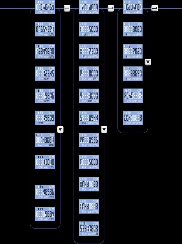
3.4 Data Display
In Data Display mode, pressing the button scrolls to the next parameter while pressing the button
toggles among Energy, Real-time Data and Counter menus.
Figure 3-3 Data Display
7CET Electric Technology
3.5 Setup Configuration via the Front Panel
Pressing the button for two seconds enters the Setup Configuration mode where the setup parameters can
be changed. Upon completion, pressing the button for two seconds returns to the Data Display mode.
3.5.1 Function of buttons
The two Front Panel buttons take on different meanings in the Setup Configuration mode and are described
below:
: Pressing this button for two seconds toggles between Data Display mode and Setup Configuration
mode. Once inside the Setup Configuration mode and at the main menu, pressing this button
selects a parameter for modification. Once selected, the parameter value blinks while it’s being
changed. If the selected parameter is a numeric value, pressing this button shifts the cursor to the
left by one position. When the cursor has reached the left-most digit, pressing this button again
will save the new setting into memory. The parameter will also stop blinking once the value has
been saved.
: Before an item is selected, pressing this button scrolls to the next setup parameter. If the selected
parameter is a numeric value, pressing this button increments the selected digit. If the selected
parameter is an enumerated value, pressing this button scrolls through the enumerated list.
Pressing the button will save the current enumerated value.
Making setup changes:
▪ Press the button for two seconds to enter the Setup Configuration mode.
▪ Press the button to advance to the Password page.
▪ A correct password must be entered before changes are allowed. The factory default password is zero. Press
the button to select the parameter for modification. Use the and buttons to enter the correct
password.
▪ Use the button to scroll to the desired parameter.
▪ Press the button to select the parameter. Once selected, the parameter value will blink.
▪ Use the and buttons to make modification to the selected parameter.
▪ Pressing the button for two seconds to exit the Setup Configuration mode.
8CET Electric Technology
3.5.2 Setup Menu
Figure 3-4 Setup Menu
9CET Electric Technology
3.5.3 Configurations
The Setup Configurations mode provides access to the following setup parameters:
Label Parameters Description Option (value) Default
PROG Programming Setup Configuration Mode / /
PW Password Enter Password 0~9999 0
SET PW Set Password Enter New Password 0~9999 -
DISC Disconnect Switch the Disconnect Relay Off/On ON/OFF ON
PF PF Convention PF Convention IEC, IEEE, -IEEE IEC
Id Unit ID COM Unit ID 1~247 100
1200/2400/4800/
Bd Baud Rate Data rate in bits per second (bps) 9600
9600/19200
COM Port
CFG Data Format 8N2/8O1/8E1/8N1 8E1
Configuration
nUM # of Windows No. of Windows for Demand Calculation 1~15 1
PErIod Period Demand Period 0~60 (min) 5(min)
LEd LED Energy Pulsing Configure LED Energy Pulsing OFF/kWh/kvarh kWh
do DO Energy Pulsing Configure DO Energy Pulsing OFF/kWh/kvarh kWh
CLr En Clear Energy Clear All Energy YES/No No
CLr
Clear Demand Clear All Demand YES/No No
dMd
CLr DI Clear DI Clear All DI counters YES/No No
Clr oT Clear Operating Time Clear running hours for device YES/No No
CLr SoE Clear SOE Clear SOE Yes/No No
CLr Cnt Clear Counters Clear both FP & COM Setup Counters YES/No No
Set Date Enter the Current Date YY-MM-DD /
Set Clock Enter the Current Time HH:MM:SS /
For example, 10002
FW Firmware Version Firmware Version means the firmware /
version is V1.00.02.
Firmware Date Firmware Version Date YYMMDD /
PROT Protocol Protocol Version e.g. 1.1 means V1.1 /
The left 5 digits The left 5 digits of SN XXXXX /
SN
The right 5 digits The right 5 digits of SN YYYYY /
Table 3-1 Configuration
10CET Electric Technology
Chapter 4 Applications
4.1 Inputs and Outputs
4.1.1 Digital Inputs
The PMC-230 comes standard with three self-excited Digital Inputs that are internally wetted at 12VDC. Digital
Inputs on the PMC-230 can be used in the following applications:
1) Status Input The digital inputs are typically used for status monitoring which can help prevent
equipment damage, improve maintenance, and track security breaches. The real-time
statuses of the Digital Inputs are available through communications. Changes in
Digital Input status are stored as events in the SOE Log in 1 ms resolution.
2) Pulse Counting Pulse counting is supported with programmable debounce and pulse weight to
facilitate WAGES (Water, Air, Gas, Electricity and Steam) information collection.
The following table describes the DI Setup Parameters that can be programmed over communications:
Setup Parameter Definition Options/Default*
DIx Function Each DI can be configured as a Status Input or Pulse Counter. 0=Status Input
1=Pulse Counter*
Specifies the minimum duration the DI must remain in the Active 1 to 9999 (ms)
DIx Debounce
or Inactive state before a DI state change is considered to be valid. 20ms*
Specifies the incremental value for each received pulse. This is only
DIx Pulse Weight 1* to 1,000,000
used when a DI is configured as a Pulse Counter.
Table 4-1 Digital Input Setup
4.1.2 Energy Pulse / 1 PPS Output
The PMC-230 comes standard with one Front Panel LED Pulse Output and one Solid State Relay Output for kWh
or kvarh Energy Pulsing. Energy Pulse Output is typically used for accuracy testing. Energy Pulsing is enabled by
default and can be disabled from the Front Panel or through communications. The Pulse Constant is fixed at 1000
impulses per kWh or kvarh. If the DO Energy Pulsing (do) parameter is disabled, the PMC-230 will output a 1PPS
signal with a pulse width of 500ms ± 0.5ms at the Energy Pulse Output terminals (E+, E-) for the accuracy testing
of its internal clock.
4.1.3 Disconnect Relay
The PMC-230 comes standard with one internal Disconnect Relay which can be manually operated via the Front
Panel or remotely controlled via communications to switch the load off or back on.
4.2 Metering
4.2.1 Basic Measurements
The PMC-230 provides real time measurements for I, U, P, Q, S, PF, Freq., U THD, I THD and Operating Time.
4.2.2 Energy Measurements
The PMC-230 provides Energy measurements for kWh, kvarh Import/Export and kVAh at a resolution of 0.01 kxh
and a maximum value of 1,000,000.00 kxh. When the maximum value is reached, it will automatically roll over
to zero. The energy measurements can be reset manually via the Front Panel or through communications as well
as preset via communications.
4.2.3 Demands
Demand is defined as the average consumption over a fixed interval (usually 15 minutes) based on the sliding
window method. The PMC-230 provides the Present Demand, Max. Demand for This Month (Since Last Reset)
and Last Month (Before Last Reset) for I, U, P, Q and S. The Present Demand and Max. Demand measurements
can be retrieved via communications, and its Setup Parameters can be configured via the Front Panel (except for
the Self-Read Time parameter) and through communications.
The PMC-230 provides the following Demand Setup parameters:
Parameter Definition Options/Default*
1 to 60 minutes. For example, if the # of Sliding Windows is set as 1 and 1 to 60 minutes,
Period the Demand Period is 15, the demand cycle will be 1×15=15min. 5*
# of Sliding
Windows Number of Sliding Windows. 1 to 15, 1*
11CET Electric Technology
The Self-Read Time allows the user to specify the time and day of the
month for the Max. Demand Self-Read operation. The Self-Read Time
supports three options:
• A zero value means that the Self-Read will take place at 00:00 of the
first day of each month.
• A non-zero value means that the Self-Read will take place at a specific
time and day based on the formula: Self-Read Time = Day x 100 + Hour
Self-Read
Time where 0 ≤ Hour ≤ 23 and 1 ≤ Day ≤ 28. For example, the value 1512 0xFFFF*
means that the Self-Read will take place at 12:00pm on the 15th day of
each month.
• A 0xFFFF value will disable the Self-Read operation and replace it with
manual operation. A manual reset will cause the Max. Demand of This
Month to be transferred to the Max. Demand of Last Month and then
reset. The terms This Month and Last Month will become Since Last
Reset and Before Last Reset.
Table 4-2 Demand Setup
4.2.4 Harmonics
The PMC-230 provides the U THD and I THD measurements which can be retrieved via the Front Panel or through
communications. There are two methods for calculating the THD:
THDf:
where I1 represents the amplitude of the fundamental component and In represents the amplitude of the
nth harmonic.
THDr:
where the denominator represents the total RMS value and the numerator represents the RMS value of the
harmonics from 2nd to 8th.
4.3 Logs
4.3.1 Monthly Energy Log
The PMC-230 stores the monthly energy data for the present month and the last 12 months. The Monthly Energy
Log Self-Read Time setup parameter allows the user to specify the time and day of the month for the Recorder’s
self-read operation via communications. The Monthly Energy Logs are stored in the meter’s non-volatile memory
and will not suffer any loss in the event of power failure, and they are stored on a First-in-First-out basis where
the newest log will overwrite the oldest one.
The Monthly Energy Log Self-Read Time supports two options:
▪ A zero value means that the Self-Read will take place at 00:00 of the first day of each month.
▪ A non-zero value means that the Self-Read will take place at a specific time and day based on the formula:
Energy Self-Read Time = Day x 100 + Hour where 0 ≤ Hour ≤ 23 and 1 ≤ Day ≤ 28. For example, the value 1512
means that the Self-Read will take place at 12:00 pm on the 15th day of each month.
The Monthly Energy Logs can be reset manually via communications.
The PMC-230 provides the following Energy data for the Present Month and the last 12 months:
Active Energy kWh Import/Export, Tariff 1 to Tariff 4 kWh Import/Export
Reactive Energy kvarh Import/Export, Tariff 1 to Tariff 4 kvarh Import/Export
Apparent Energy kVAh, Tariff 1 to Tariff 4 kVAh
Table 4-3 Energy Measurement for Monthly Energy Log
12CET Electric Technology
4.3.2 SOE Log
The PMC-230’s SOE Log can store up to 32 events such as Power-on, Power-off, Digital Input Status changes,
Disconnect Relay Status changes, Self-diagnostics and Setup changes in its non-volatile memory. Each event
record includes the event classification, its relevant parameter values and a timestamp in ±1ms resolution. The
SOE Log can be retrieved via communications for display. If there are more than 32 events, the newest event will
replace the oldest one on a First-in-First-Out basis. The SOE Log can be reset through the Front Panel or via
communications.
4.3.3 Data Recorder Log
The PMC-230 provides one Data Recorder capable of recording 16 parameters at a 5-min interval for 6 months.
The Data Recorder log is stored in the device’s non-volatile memory and will not suffer any loss in the event of a
power failure.
The programming of the Data Recorder is only supported over communications. The Data Recorder provides the
following setup parameters.
Parameters Value/Option Default
Trigger Mode 0=Disabled / 1=Triggered by Timer 1
Recording Mode 0=Stop-When-Full / 1=First-In-First-Out 1
Recording Depth 1 to 65535 (entry) 60000
Recording Interval 1 to 3,456,000 seconds 300s
Offset Time 0 to 43,200 seconds, 0 indicates no offset. 0
Number of Parameters 0 to 16 14
Parameter 1 to 16 See Table 5-28 Data Recorder Parameters See Table 5-27 Data Recorder Setup
Table 4-4 Data Recorder Setup
The Data Recorder Log is only operational when the values of Trigger Mode, Recording Depth, Recording Interval,
and Number of Parameters are all non-zero.
The Recording Offset can be used to delay the recording by a fixed time from the Recording Interval. For example,
if the Recording Interval parameter is set to 3600 (hourly) and the Recording Offset parameter is set to 300 (5
minutes), the recording will take place at 5 minutes after the hour every hour, i.e. 00:05, 01:05, 02:05, etc. The
value of the Recording Offset parameter should be less than the Recording Interval parameter.
The following formula can be used to calculate how many bytes would be required for the Data Recorder with n
parameters where 0 ≤ n ≤ 16.
No. of Bytes per Record = n x 4 + Timestamp @ 8 bytes
With 16 parameters, the no. of bytes required = 16 x 4 + 8 = 72 bytes. It should be noted that the above
calculation is used to illustrate the internal organization of the data storage and is only an approximation of the
actual implementation. The following table defines the maximum Recording Depth can be set for the different
number of parameters.
No. of Parameters Max. Recording Depth No. of Parameters Max. Recording Depth
1 65535 9 65535
2 65535 10 65535
3 65535 11 65535
4 65535 12 65535
5 65535 13 65535
6 65535 14 64400
7 65535 15 60600
8 65535 16 57200
Table 4-5 Max. Recording Depth for Different No. of Parameters
13CET Electric Technology
4.4 Time of Use (TOU)
TOU is used for Electricity Pricing that varies depending on the time of day, day of week, and season. The TOU
system allows the user to configure an electricity price schedule inside the PMC-230 and accumulate energy
consumption into different TOU tariffs based on the time of consumption. TOU programming is only supported
through communications.
The TOU feature on PMC-230 supports two TOU schedules, which can be switched at a pre-defined time. Each
TOU schedule supports:
▪ Up to 4 Seasons
▪ 30 Holidays or Alternate Days
▪ 12 Daily Profiles, each with 8 periods in 15-minute interval
▪ 4 Tariffs
Each TOU Schedule has the following setup parameters and can only be programmed via communications:
Parameters Definition Options
Specify a daily rate schedule which can be divided into a 1 to 12, the first period
maximum of 8 periods in 15-min intervals.
Daily Profile # Up to 12 Daily Profiles can be programmed for each TOU starts at 00:00 and the
last period ends at 24:00.
schedule.
A year can be divided into a maximum of 4 seasons. Each
1 to 4, starting from
Season # season is specified with a Start Date and ends with the next January 1st
season’s Start Date.
A day can be defined as an Alternate Day, such as May 1st. Each
Alternate Days # 1 to 30.
Alternate Day is assigned a Daily Profile.
Specify the day type of the week. Each day of a week can be Weekday1, Weekday2,
Day Types assigned a day type such as Weekday1, Weekday2, Weekday3 Weekday3 & Alternate
and Alternate Days. The Alternate Day has the highest priority. Days.
Specify when to switch from one TOU schedule to another.
Format: YYYYMMDDHH
Switching Time Writing 0xFFFFFFFF to this parameter disables switching Default=0xFFFFFFFF
between TOU schedules.
Table 4-6 TOU Setup
For each of the 4 Tariffs, the PMC-230 provides the kWh, kvarh Import/Export and kVAh measurement.
14CET Electric Technology
Chapter 5 Modbus Map
This chapter provides a complete description of the Modbus register map (Protocol Version 1.0) for the PMC-
230 to facilitate the development of 3rd party communications driver for accessing information on the PMC-230.
The PMC-230 supports the following Modbus functions:
1) Read Holding Registers (Function Code 0x03)
2) Force Single Coil (Function Code 0x05)
3) Preset Multiple Registers (Function Code 0x10)
For a complete Modbus Protocol Specification, please visit http://www.modbus.org.
The following table provides a description of the different data formats used for the Modbus registers. The PMC-
230 uses the Big Endian byte ordering system.
Format Description
UINT16/INT16 Unsigned/Signed 16-bit Integer
UINT32/INT32 Unsigned/Signed 32-bit Integer
Float IEEE 754 32-bit
Single Precision Floating Point Number
5.1 Basic Measurements
Register Property Description Format Scale Unit
0000 RO U Float V
0002 RO I Float A
0004 RO P Float kW
0006 RO Q Float x1 kvar
0008 RO S Float kVA
0010 RO PF Float --
0012 RO Frequency Float Hz
0014~0039 -- Reserved -- -- --
0040 RO FP Counter1 UINT16
0~9999
0041 RO Comm. Counter1 UINT16
0042 RO DI Status2 UINT16
0043 RO Disconnect Relay Status3 UINT16
0044 RO Operating Time UINT32 x0.1 Hour
0046 RO SOE Log Pointer4 UINT32 -- --
0048 RO Data Recorder Log Pointer4 UINT32 -- --
Table 5-1 Basic Measurements
Notes:
1. The FP Counter and Comm. Counter will be incremented every time some important setup parameters, which may affect the accuracy
of Energy registers and DI Pulse Counters or the way they are calculated, are changed via the Front Panel or communications,
respectively. The FP Counter is incremented every time a relevant setup parameter is changed via the Front Panel, while the Comm.
Counter is incremented every time a single packet is sent to change one or more relevant setup parameters through communications.
The following actions may trigger these counters to increment:
▪ Changing Setup Parameters:
o DI setup parameters
o LED Energy Pulse
o DO Energy Pulse
o Preset Energy Value
o Demand Period and No. of Sliding Windows
o TOU setup registers
o Manual Time Set
▪ Clear Actions via the Front Panel:
o Clear All Energy
o Clear All Demand
o Clear Operating Time
o Clear All DI Counters
▪ Clear Actions via communications:
o Clear Historical Monthly Energy (Register 9600)
o Clear Real Time Energy (Register 9601)
o Clear Monthly Energy Log of Present Month (Register 9602)
o Clear All Energy Logs (Register 9603)
o Clear Max. Demand Log of This Month (Register 9605)
o Clear All Demand (Register 9606)
o Clear Device Operating Time (Register 9607)
o Clear All Data (Register9614)
o Clear DI1 Counter (Register 9609)
o Clear DI2 Counter (Register 9610)
o Clear DI3 Counter (Register 9611)
o Clear All DI Counters (Register 9612)
15CET Electric Technology
2. For the DI Status register, the bit values of B0 to B2 represent the states of DI1 to DI3, respectively, with “1” meaning Active (Closed)
and “0” meaning Inactive (Open).
3. For the Disconnect Relay Status register, the returned value “1” means Connected while “0” means Disconnected.
4. The PMC-230 has one SOE Log and one DR Log. Each of these logs has a Log Pointer that indicates its current logging position. The range
of the Log Pointer is between 0 and 0xFFFFFFFF, and it is incremented by one for every new log generated and will roll over to 0 if its
current value is 0xFFFFFFFF. If a Clear Log is performed through the Front Panel or via communications, its Log Pointer will be reset to
zero, and the SOE Log Pointer will be immediately incremented by one with a new “Clear SOE” event. When the SOE or DR Log Pointer
is larger than the respective Log Depth, the latest 32 SOE logs or up to 65,535 DR Logs are stored on a FIFO basis.
5.2 Real Time Energy Measurements
Register Property Description Format Scale Unit
0500 RW kWh Import INT32
kWh
0502 RW kWh Export INT32
0504 RW kvarh Import INT32
kvarh
0506 RW kvarh Export INT32
0508 RW kVAh INT32 kVAh
0510 RW kWh Import of T1 INT32
kWh
0512 RW kWh Export of T1 INT32
0514 RW kvarh Import of T1 INT32
x0.01 kvarh
0516 RW kvarh Export of T1 INT32
0518 RW kVAh of T1 INT32 …
0520~0538 … … INT32 kWh
0540 RW kWh Import of T4 INT32
kWh
0542 RW kWh Export of T4 INT32
0544 RW kvarh Import of T4 INT32
kvarh
0546 RW kvarh Export of T4 INT32
0548 RW kVAh of T4 INT32 kVAh
Table 5-2 Energy Measurements
5.3 DI Pulse Counter
Register Property Description Format Range/Unit
1200 RW DI1 Pulse Counter INT32
1202 RW DI2 Pulse Counter INT32 0 to 99,999,999
1204 RW DI3 Pulse Counter INT32
Table 5-3 DI Pulse Counter
5.4 Harmonic Measurement
Register Property Description Format Scale/Unit
1300 RO I THD Float
x1, 0.1 means 10%
1302 RO U THD Float
Table 5-4 Harmonic Measurements
5.5 Demand Measurements
5.5.1 Present Demand
Register Property Description Format Scale Unit
3000 RO U Float U
3002 RO I Float A
3004 RO P Float x1 kW
3006 RO Q Float kvar
3008 RO S Float kVA
Table 5-5 Present Demand
5.5.2 Max. Demand of This Month (Since Last Reset)
Register Property Description Format Scale Unit
3400~3405 RO U U
3406~3411 RO I See A
3412~3417 RO P Table 5-8 Demand Data x1 kW
3418~3423 RO Q Structure kvar
3424~3429 RO S kVA
Table 5-6 Max. Demand of This Month
16CET Electric Technology
5.5.3 Max. Demand of Last Month (Before Last Reset)
Register Property Description Format Scale Unit
3600~3605 RO U U
3606~3611 RO I See A
3612~3617 RO P Table 5-8 Demand Data x1 kW
3618~3623 RO Q Structure kvar
3624~3629 RO S kVA
Table 5-7 Max. Demand of Last Month
5.5.4 Demand Data Structure
Offset Format Description
High-order Byte Year - 2000 (0-37)
+0 INT16
Low-order Byte Month (1-12)
High-order Byte Day (1-31)
+1 INT16
Low-order Byte Hour (0-23)
High-order Byte Minute (0-59)
+2 INT16
Low-order Byte Second (0-59)
+3 - INT16 Millisecond (0 to 999)
+4~+5 - Float Record Value
Table 5-8 Demand Data Structure
5.6 Logs
5.6.1 Monthly Energy Log
Register Property Description Format Scale Unit
0980 RW Month1 INT16 0 to 12
High-order Byte: Year (0-37)
0981 RO INT16
Low-order Byte: Month (1-12)
Time Stamp2
High-order Byte: Day (1-31)
0982 RO Low-order Byte: Hour (0-23) INT16 (20YY/MM/DD
HH:MM:SS)
High-order Byte: Minute (0-59)
0983 RO Low-order Byte: Second (0-59) INT16
0984 RO kWh Import INT32
kWh
0986 RO kWh Export INT32
0988 RO kvarh Import INT32
kvarh
0990 RO kvarh Export INT32
0992 RO kVAh INT32 kVAh
0994 RO kWh Import of T13 INT32
kWh
0996 RO kWh Export of T13 INT32
0998 RO kvarh Import of T13 INT32
x0.01 kvarh
1000 RO kvarh Export of T13 INT32
1002 RO kVAh of T13 INT32 kVAh
1004~1022 RO … INT32 …
1024 RO kWh Import of T43 INT32
kWh
1026 RO kWh Export of T43 INT32
1028 RO kvarh Import of T43 INT32
kvarh
1030 RO kvarh Export of T43 INT32
1032 RO kVAh of T43 INT32 kVAh
Table 5-9 Monthly Energy Log
Notes:
1. This register represents the Month when it is read. To read the Monthly Energy Log, this register must be first written to indicate to
the PMC-230 which log to load from memory. The range of this register is from 0 to 12, which represents the Present Month and the
Last 12 Months. For example, if the current month is 2016/10, “0” means 2016/10, “1” means 2016/09, “2” means 2016/08, ……”12”
means “2015/10”.
2. For each Monthly Energy Log, the time stamp shows the exact self-read time (20YY/MM/DD HH:MM:SS) when the log was recorded.
For the Monthly Energy Log of the Present Month, the time stamp shows the current time of the meter because the present month is
not yet over.
3. T1 to T4 means Tariff 1 to Tariff 4.
5.6.2 Data Recorder Log
Register Property Description Format Note
20000 RW Data Recorder Index UINT32 See Note 1)
High-order Byte: Year 1 to 37 (Year-2000)
20002 RO UINT16
Low-order Byte: Month 1 to 12
20003 RO High-order Byte: Day UINT16 1 to 31
17CET Electric Technology
Low-order Byte: Hour 0 to 23
High-order Byte: Minute 0 to 59
20004 RO UINT16
Low-order Byte: Second 0 to 59
20005 RO Millisecond UINT16
20006~20007 RO Parameter 1 Float
20008~20009 RO Parameter 2 Float
20010~20011 RO Parameter 3 Float
20012~20013 RO Parameter 4 Float
20014~20015 RO Parameter 5 Float
20016~20017 RO Parameter 6 Float
20018~20019 RO Parameter 7 Float
20020~20021 RO Parameter 8 Float
20022~20023 RO Parameter 9 Float
20024~20025 RO Parameter 10 Float
20026~20027 RO Parameter 11 Float
20028~20029 RO Parameter 12 Float
20030~20031 RO Parameter 13 Float
20032~20033 RO Parameter 14 Float
20034~20035 RO Parameter 15 Float
20036~20037 RO Parameter 16 Float
Table 5-10 Data Recorder
Note:
1) Writing a value n to the Data Recorder Index will load the nth Log into the buffer from memory, and the valid range of the DR Index is:
Between 1 and DR Log Pointer when DR Log Pointer ≤ DR Log Depth (see Section 5.9 for DR Log Depth)
Between DR Log Pointer - (DR Log Depth - 1) and DR Log Pointer when the DR Log Pointer > DR Log Depth
5.6.3 SOE Log
The SOE Log Pointer points to the current logging position within the SOE Log where the next event will be
stored. The following formula is used to determine the starting register address of the SOE log referenced by a
particular SOE Log Pointer value:
Register Address = 10000 + Modulo[(SOE Log Pointer-1)/32]*8
Register Property Description Format
10000~10007 RO Event 1
10008~10015 RO Event 2
10016~10023 RO Event 3 See Table 5-12 SOE Log
Data Structure
10024~10031 RO Event 4
…… …
10248~10255 RO Event 32
Table 5-11 SOE Log
SOE Log Data Structure
Offset Property Description Unit
RO High-order Byte: Event Classification See Table 5-13 SOE
+0 Classification
RO Low-order Byte: Sub-Classification
RO High-order Byte: Year 0-37 (Year-2000)
+1
RO Low-order Byte: Month 1 to 12
RO High-order Byte: Day 1 to 31
+2
RO Low-order Byte: Hour 0 to 23
RO High-order Byte: Minute 0 to 59
+3
RO Low-order Byte: Second 0 to 59
+4 RO Record Time: Millisecond 0 to 999
RO High-order Byte: Reserved -
+5
RO Low-order Byte: Status1 -
+6 RO High-order Word: Event Value (Float) -
+7 RO Low-order Word: Event Value (Float) -
Table 5-12 SOE Log Data Structure
Notes:
1. The value “1” means DI Inactive or Disconnect Relay Operated, while the value “2” means DI Active or Disconnect Relay Released.
18CET Electric Technology
SOE Classification
Event Sub- Status Event Description
Classification Classification Value
1 1/2 0 1=DI1 Inactive, 2=DI1 Active
1=DI Changes 2 1/2 0 1=DI2 Inactive, 2=DI2 Active
3 1/2 0 1=DI3 Inactive, 2=DI3 Active
1 1/2 0 1=Relay Operated, 2=Relay Released via Comm.
2=Relay Status 1=Relay Operated, 2=Relay Released via the
2 1/2 0
Front Panel
1 0 0 Flash Fault
4=Self-diagnostic 2 0 0 FRAM Fault
3 0 0 System Parameters Fault
1 0 0 Power On
2 0 0 Power Off
3 0 0 Clear All Energy via Front Panel
4 0 0 Clear All Demand via Front Panel
5 0 0 Clear All DI Counters via Front Panel
6 0 0 Clear Operating Time via Front Panel
7 0 0 Clear SOE via Front Panel
8 0 0 Clear Setup Counters via Front Panel
9 0 0 Set Clock via Front Panel
10 0 0 Setup Changes via Front Panel
11 to 20 -- -- Reserved
21 0 0 Clear Real Time Energy via Comm.
22 0 0 Clear Historical Monthly Energy Log via Comm.
23 0 0 Clear Present Monthly Energy via Comm.
24 0 0 Clear All Energy Logs via Comm.
25 0 0 Clear Max. Demand of This Month via Comm.
5=Operations
26 0 0 Clear All Demand via Comm.
27 0 0 Clear All Data via Comm.
28 0 0 Clear SOE via Comm.
29 0 0 Clear All DI Counters via Comm.
30 0 x=1 to 3 Clear DIx Counter via Comm.
31 0 0 Clear Operating Time via Comm.
32 0 0 Factory Restore via Comm.
33 0 0 Setup Changes via Comm.
34 0 0 Preset Energy via Comm.
35 0 0 Preset TOU Energy via Comm.
36 0 1 to 4 Switch TOU Schedule1
37 0 0 Clear Data Recorder via Comm.
38 0 0 Clear Setup Counters via Comm.
39 0 0 Set Clock via Comm.
40 0 0 Communication locked out for 15 minutes after
3 incorrect password attempts!
Table 5-13 SOE Classification
Note:
1. The event values of Switch TOU Schedule are illustrated in the table below:
Record Value Description
1 Switch Schedule 1 to Schedule 2 manually
2 Switch Schedule 2 to Schedule 1 manually
3 Switch Schedule 1 to Schedule 2 automatically
4 Switch Schedule 2 to Schedule 1 automatically
Table 5-14 TOU Switch Records
19CET Electric Technology
5.7 Device Setup
5.7.1 Basic Setup
Register Property Description Format Range, Default*
6000 WO Comm. Authorization1 UINT16 0~9999
6001 RW PF Convention UINT16 0=IEC*, 1=IEEE, 2=-IEEE
6002 RW THD Calculation2 UINT16 0= THDf*, 1= THDr
Current Threshold of Device
6003 RW Operating Time UINT16 1 to 1000 (x0.001 In), 4*
6004 RW LED Energy Pulse UINT16 0=Disabled, 1=kWh*, 2=kvarh
6005 RW Demand Period UINT16 1 to 60 (min), 5*
6006 RW No. of Windows UINT16 1 to 15, 1*
6007 RW Self-read Time3 UINT16 0xFFFF*
Monthly Energy Log Self-read
6008 RW Time4 UINT16 100
6009 RW Default Display5 UINT16 0=kWh Import*, 1=Auto-Scroll
6010 RW MBPW - Modbus Password6 UINT16 0=Disabled*, 1=Enabled
6011 RW Comm. Password6 UINT16 0 to 9999, 9999*
6012 RW Front Panel Password6 UINT16 0 to 9999, 0000*
6013 RW Arm before execute UINT16 0=Disabled*, 1=Enabled
6014 RW Time Zone7 UINT16 0 to 32, 29 (GMT+10:00)*
Table 5-15 Basic Setup
Notes:
1. The Comm. Authorization is the register to which the master software would be required to write the correct Comm. Password before
it’s allowed to perform any Modbus Read/Write operations with the PMC-230, if the MBPW (Modbus Password) register is enabled. If
the Comm. Password is correct, the master software will be able to communicate with the same PMC-230 continually until there is a
period of inactivity of 60 seconds or longer. When this happens, the master software will have to write to the Comm. Authorization
register again to re-gain access to the PMC-230. If an incorrect Comm. Password has been written to the Comm. Authorization register
for 3 consecutive times, Modbus access will be locked out for approximately 15 minutes.
2. There are two ways to calculate THD:
THDf:
where I1 represents the amplitude of the fundamental component and In represents the amplitude of the nth harmonic.
THDr:
where the denominator represents the total RMS value and the numerator represents the RMS value of the harmonics from 2nd to 8th.
3. The Self-Read Time applies to the Max. Demand Log and supports the following three options:
• A zero value means that the Self-Read will take place at 00:00 of the first day of each month.
• A non-zero value means that the Self-Read will take place at a specific time and day based on the formula: Self-Read Time = (Day x
100 + Hour) where 0 ≤ Hour ≤ 23 and 1 ≤ Day ≤ 28. For example, the value 1512 means that the Self-Read will take place at 12:00
pm on the 15th day of each month.
• A 0xFFFF value means the automatic self-read operation is disabled and replaced with manual operation.
4. The Monthly Energy Log Self-Read Time supports the following options:
• A Zero value means that the Self-Read will take place at 00:00 of the first day of each month,
• A non-zero value means that the Self-Read will take place at a specific time and day based on the formula: Self-Read Time = (Day x
100 + Hour) where 0 ≤ Hour ≤ 23 and 1 ≤ Day ≤ 28. For example, the value 1512 means that the Self-Read will take place at 12:00
pm on the 15th day of each month.
5. Under Auto-Scroll mode, the kWh/kvarh Imp./Exp. and kVAh as well as kWh Imp./Exp. per Tariff are displayed sequentially in 4 seconds
interval.
6. The MBPW register is disabled by default and should be enabled if communication security is required.
7. The following table lists the Time Zones supported:
Code Time Zone Code Time Zone
0 GMT-12:00 17 GMT+03:30
1 GMT-11:00 18 GMT+04:00
2 GMT-10:00 19 GMT+04:30
3 GMT-09:00 20 GMT+05:00
4 GMT-08:00 21 GMT+05:30
5 GMT-07:00 22 GMT+05:45
6 GMT-06:00 23 GMT+06:00
7 GMT-05:00 24 GMT+06:30
20CET Electric Technology
8 GMT-04:00 25 GMT+07:00
9 GMT-03:30 26 GMT+08:00
10 GMT-03:00 27 GMT+09:00
11 GMT-02:00 28 GMT+09:30
12 GMT-01:00 29 GMT+10:00
13 GMT+00:00 30 GMT+11:00
14 GMT+01:00 31 GMT+12:00
15 GMT+02:00 32 GMT+13:00
16 GMT+03:00
Table 5-16 Time Zones
5.7.2 I/O Setup
Register Property Description Format Range, Default*
6200 RW DI1 Function UINT16 0=Status Input, 1=Pulse Counter*
6201 RW DI2 Function UINT16 0=Status Input, 1=Pulse Counter*
6202 RW DI3 Function UINT16 0=Status Input, 1=Pulse Counter*
6203 RW DI1 Debounce UINT16 1 to 9999ms, 20ms*
6204 RW DI2 Debounce UINT16 1 to 9999ms, 20ms*
6205 RW DI3 Debounce UINT16 1 to 9999ms, 20ms*
6206 RW DI1 Pulse Weight UINT32 1 to 1,000,000, 1*
6208 RW DI2 Pulse Weight UINT32 1 to 1,000,000, 1*
6210 RW DI3 Pulse Weight UINT32 1 to 1,000,000, 1*
6212 RW DO Energy Pulse UINT16 0=Disabled, 1=kWh*, 2=kvarh
Table 5-17 I/O Setup
5.7.3 Communication Setup
Register Property Description Format Range, Default*
6501 RW Unit ID UINT16 1 to 247, 100*
6502 RW Baud Rate UINT16 0=1200, 1=2400, 2=4800, 3=9600*, 4=19200,
COM Port
6503 RW UINT16 0=8N2, 1=8O1, 2=8E1*, 3=8N1
Data Format
Table 5-18 Communication Setup
5.8 TOU Setup
5.8.1 Basic
Register Property Description Format Range, Default*
7000 RO Current Tariff1 UINT16 0=T1*, 1=T2, 2=T3, 3=T4
7001 RO Current Season UINT16 0* to 3 (Season #1 to #4)
7002 RO Current Period UINT16 0* to 7 (Period #1 to #8)
7003 RO Current Daily Profile UINT16 0* to 11 (Daily Profile #1 to #12)
0=Weekday1*, 1=Weekday2
7004 RO Current Day Type UINT16 2=Weekday3, 3=Alternate Day
7005 RO Current TOU Schedule No UINT16 0=TOU #1*, 1=TOU #2
7006 RW TOU Switch Time1 UINT32 0xFFFFFFFF*
7008 WO Switch TOU Manually UINT16 Write 0xFF00 to manually switch
the TOU schedule
7009 RW Sunday Setup UINT16
7010 RW Monday Setup UINT16
7011 RW Tuesday Setup UINT16 0*=Weekday1
7012 RW Wednesday Setup UINT16 1=Weekday2
7013 RW Thursday Setup UINT16 2=Weekday3
7014 RW Friday Setup UINT16
7015 RW Saturday Setup UINT16
Table 5-19 TOU – Basic Setup
Notes:
1) The following table illustrates the data structure for the TOU Switch Time. For example, 0x1003140C indicates a switch time of 12:00 pm
on March 20th, 2016. Writing 0xFFFFFFFF to this register disables the switching between TOU Schedule.
Byte 3 Byte 2 Byte 1 Byte 0
Year-2000 (0-37) Month (1-12) Day (1-31) Hour (00-23)
Table 5-20 TOU Switch Time Format
21You can also read