POSE ESTIMATION OF A MOVING CAMERA WITH LOW-COST, MULTI-GNSS DEVICES
←
→
Page content transcription
If your browser does not render page correctly, please read the page content below
The International Archives of the Photogrammetry, Remote Sensing and Spatial Information Sciences, Volume XLIII-B2-2020, 2020
                                                 XXIV ISPRS Congress (2020 edition)

        POSE ESTIMATION OF A MOVING CAMERA WITH LOW-COST, MULTI-GNSS
                                   DEVICES

                     Manolis Lourakis1, ∗, Maria Pateraki1 , Ion-Anastasios Karolos2 , Christos Pikridas2 , Petros Patias2
                 1
                  Institute of Computer Science, Foundation for Research and Technology – Hellas, Heraklion, Greece
                                                    (lourakis, pateraki)@ics.forth.gr
                2
                  School of Rural & Surveying Engineering, Aristotle University of Thessaloniki, Thessaloniki, Greece
                                                 (ikarolos, cpik, patias)@topo.auth.gr

                                                           Commission II, WG 1

KEY WORDS: Pose, georeferencing, exterior orientation, absolute orientation, multi-GNSS, RTK

ABSTRACT:

Without additional prior information, the pose of a camera estimated with computer vision techniques is expressed in a local
coordinate frame attached to the camera’s initial location. Albeit sufficient in many cases, such an arbitrary representation is not
convenient for employment in certain applications and has to be transformed to a coordinate system external to the camera before
further use. Assuming a camera that is firmly mounted on a moving platform, this paper describes a method for continuously
tracking the pose of that camera in a projected coordinate system. By combining exterior orientation from a known target with
incremental pose changes inferred from accurate multi-GNSS positioning, the full 6 DoF pose of the camera is updated with low
processing overhead and without requiring the continuous visual tracking of ground control points. Experimental results of applying
the proposed method to a moving vehicle and a mobile port crane are reported, demonstrating its efficacy and potential.

                       1. INTRODUCTION                                   (RTK) (Rietdorf et al., 2006) that combine measurements of the
                                                                         phase of the radio signal’s carrier wave with real-time correc-
Geometric computer vision can provide a wealth of measure-               tions from an accurately known reference station, GNSS devices
ments about an imaged scene (Hartley, Zisserman, 2004). With-            can attain centimetre positional accuracy. Such receivers have
out any additional prior information, these measurements are             been the standard practice in airborne mapping applications but
nevertheless expressed in an arbitrary local coordinate system           their utilization in other application domains in need of high
related to the employed camera, e.g. (Snavely et al., 2008).             accuracy has been constrained by their large size and high cost.
Furthermore, monocular 3D reconstruction is possible only up             Promising solutions have emerged from the recent advent of
to an isotropic scaling, i.e. the 3D structure and the transla-          compact, low-cost multi-GNSS devices which offer further ac-
tional component of camera motion are defined up to an un-               curacy and increased coverage benefits by intelligently using
known scale factor (Lourakis, Zabulis, 2013a). However, such             the largest number of visible satellites from different GNSS
a scaled, camera-centered representation is not always suitable,         satellite constellations (U-blox, 2020).
especially when camera measurements need to be combined
with map data. To deal with this issue, the camera should be             This paper describes and evaluates an approach for georeferen-
georeferenced, i.e. its local coordinate system should be aligned        cing a pinhole camera rigidly mounted on a mobile platform. It
with a ground coordinate system (Hackeloeer et al., 2014).               employs a set of visually distinct ground control points to geor-
                                                                         eference the camera at a reference location, combined with a
The task of estimating the 6D camera position and orientation            stream of position information acquired from a triplet of com-
with respect to an external coordinate system is commonly re-            pact, low-cost GNSS receivers. The ground control points have
ferred to as exterior orientation. The computation of the ex-            been surveyed with an RTK GNSS receiver and their surveyed
terior orientation parameters usually relies on the measurement          coordinates were converted to a Transverse Mercator projec-
of ground control points, which in the case of non-stationary            tion coordinate system (Veis, Paradissis, 1990). Camera exter-
cameras with limited control over their motion and the partic-           ior orientation using the ground control points and their image
ularities of the imaged environment, is a practical limitation.          projections is then performed. This computation is carried out
Especially when operating outdoors, automatic feature extrac-            in a robust regression framework to mitigate the effect of mis-
tion and matching is challenged by highly homogeneous areas,             localized or mismatched image points. A triplet of compact,
repetitive textures, large variations in illumination and occlu-         low-cost multi-band GNSS receivers that are firmly attached to
sions, and its failure can severely impact the accuracy and re-          different locations on the platform provides the reference co-
liability of the estimated measurements. Such obstacles can be           ordinates of three platform points. As the platform moves to
overcome by solutions based on non-visual sensors.                       new locations, the coordinates of these three platform points
                                                                         are continuously measured. Solving for the absolute orientation
Global navigation satellite systems (GNSS) devices can provide           between the reference and the most recently measured locations
the three-dimensional geodetic coordinates of measured envir-            of the platform points estimates the motion of the platform rel-
onment points in real-time (Fotiou, Pikridas, 2012). When in-            ative to the reference points. Finally, the camera pose at a new
corporating differential techniques such as real-time kinematic          location is obtained by combining the camera reference pose
∗   Corresponding author.                                                with the platform motion.

                                                   This contribution has been peer-reviewed.
                     https://doi.org/10.5194/isprs-archives-XLIII-B2-2020-55-2020 | © Authors 2020. CC BY 4.0 License.                 55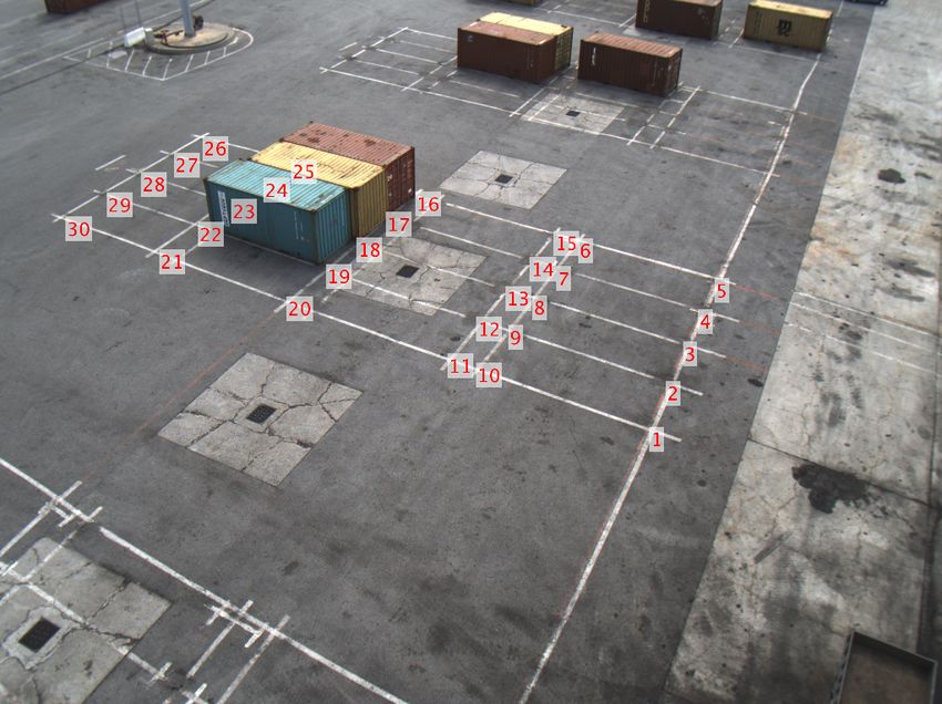
The International Archives of the Photogrammetry, Remote Sensing and Spatial Information Sciences, Volume XLIII-B2-2020, 2020
                                               XXIV ISPRS Congress (2020 edition)

The proposed method has low computational overhead, thus it         e.g. (Hays, Efros, 2008, Zhang, Kosecka, 2006). Often, these
can provide pose estimates at high frequency. No special con-       approaches apply structure from motion (SfM) techniques (Hart-
straints or adaptations of the camera installation are required.    ley, Zisserman, 2004, Schönberger, Frahm, 2016) to images an-
Furthermore, the ground control points need to be surveyed          notated with geographic information in order to recover geore-
only once and used off-line for estimating the camera exterior      ferenced scene structure and camera locations. For example, (Li
orientation at the reference location. In contrast to most exist-   et al., 2012) perform landmark recognition on large, geore-
ing approaches for camera georeferencing, the surveyed ground       gistered 3D point clouds and estimate pose from the matches
points need not always be visible in images and the camera is       established among image features and 3D points. This is the
allowed to move freely in the environment. It is only required      most relevant work to our proposed approach, with three major
that the ground control points are visible from the reference       differences being that our approach i) can operate in environ-
location. The remainder of the paper is organized as follows.       ments whose appearance can change drastically over time, ii)
Relevant previous work is briefly reviewed in Section 2. Sec-       does not need to continuously track visual features and iii) is
tion 3 provides an overview of some background information.         significantly cheaper in terms of computational cost. Georegis-
The proposed approach is detailed in Section 4. Experimental        tration of point clouds obtained by SfM is achieved by ground
results are presented in Section 5 and the paper is concluded in    surveying a small set of points which are either clearly visible
Section 6.                                                          in a scene and its corresponding point cloud or correspond to
                                                                    high-contrast artificial targets introduced to a scene before im-
                                                                    age acquisition (Westoby et al., 2012).
                   2. PREVIOUS WORK
                                                                    Despite the promising results obtained with the use of geo-
Camera georeferencing, i.e. determining the location where an       tagged objects, this approach is limited by the need to cope
image was acquired, has been studied, often independently, by       with voluminous amounts of data and the fact that the avail-
both the photogrammetry and the computer vision communit-           able geo-tagged images are clustered in urban areas with the
ies. Despite recent progress, automatic georeferencing of im-       vast majority of the Earth’s surface having no such coverage.
ages remains a challenging task (Zamir et al., 2016).               For this reason, more recent research explores cross-view image
                                                                    matching (Regmi, Shah, 2019, Lin et al., 2013), and attempts to
For more than 20 years, direct georeferencing, i.e. camera device   directly match a ground image with aerial images. This match-
exterior orientation via the integration of GNSS and inertial       ing has to overcome the dramatic variation in image appearance
(IMU) measurements from on-board sensors, has been a stand-         that is caused by the large disparity in viewpoints.
ard photogrammetric procedure for airborne and satellite im-
ages (Cramer et al., 2001). This is especially the case for air-
borne linear imaging sensors (Pateraki, 2005), for which orient-                         3. BACKGROUND
ation parameters have to be estimated for each set of scan lines
due to the high motion dynamics. Beyond the aerial domain,          The following subsections provide brief overviews of key con-
mobile mapping systems driven by high accuracy requirements         cepts that are of central importance for the development of the
have emerged in terrestrial and marine environments, employ-        proposed method in Section 4.
ing bulky and expensive equipment (Cavegn et al., 2018). To
overcome issues with GNNS signal degradation experienced            3.1   Dynamic time warping
in ground-based systems, (Nebiker et al., 2012, Jende et al.,
2017) proposed the fusion of ground-based imagery from mo-          Dynamic time warping (DTW) (Sakoe, Chiba, 1978) is a tech-
bile mapping systems with aerial imagery. Despite their lim-        nique for finding an optimal alignment between two time de-
ited payload and battery autonomy, current unmanned aerial          pendent sequences under certain constraints. An alignment is
vehicles (UAVs) can be equipped with miniaturized high res-         a warping that maps one time series onto another in order to
olution cameras, accurate GNSS receivers and reliable IMUs,         facilitate their similarity comparison. DTW can be efficiently
thereby facilitating affordable direct georeferencing (Gabrlik,     computed by using the dynamic programming paradigm, which
2015).                                                              is a general method for reducing the running time of algorithms
                                                                    exhibiting the properties of overlapping subproblems and op-
The earliest works concerned with georeferencing in the com-        timal substructure. In our case, the GNSS position sequences
puter vision literature also focused on airborne or satellite im-   are timestamped and DTW is used to synchronize them using
ages. For example, (Wildes et al., 2001) register a video stream    the absolute difference of timestamps as the local cost meas-
augmented with telemetry to geodetically calibrated reference       ure. The timestamps are generated by Raspberry Pi computers
imagery in the form of a digital orthoimage and elevation map.      attached to the employed GNSS receivers, whose clocks are as-
(Shan et al., 2014) perform ground to aerial image matching         sumed to be approximately synchronized with an external time
in order to georegister ground-based multi-view stereo mod-         server using the Network Time Protocol (NTP) (Mills, 1991).
els. (Hourdakis, Lourakis, 2015) match a sparse, geometric rep-
resentation between ground and orbital images and use it to         3.2   Camera Pose Estimation
refine the pose of ground images initially obtained via visual
odometry.                                                           Camera pose estimation concerns the determination of a cam-
                                                                    era’s position and orientation with respect to its environment
The advent of consumer digital photography two decades ago          given the camera intrinsic parameters and a set of correspond-
combined with the ease of storing and sharing such data, has        ences between 3D features and their image projections (Hart-
led to an explosion in consumer digital image production. As        ley, Zisserman, 2004). In the photogrammetry literature, the
a result, attention was shifted to images obtained from ground-     problem is also known as exterior orientation (Grussenmeyer,
level viewpoints and with less controlled acquisition proced-       Al Khalil, 2002). When the corresponding features are n pairs
ures. The prevailing paradigm has been to adopt an image re-        of points, the problem is often referred to as the Perspective-n-
trieval strategy driven by large datasets of geo-tagged images,     Point (PnP) problem. PnP is typically solved using non-iterative

                                                This contribution has been peer-reviewed.
                  https://doi.org/10.5194/isprs-archives-XLIII-B2-2020-55-2020 | © Authors 2020. CC BY 4.0 License.               56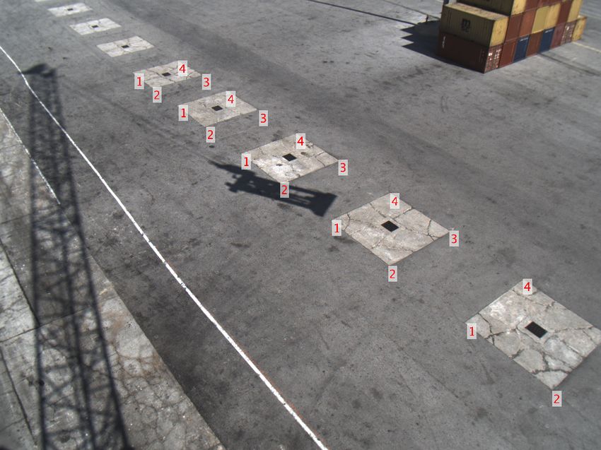
The International Archives of the Photogrammetry, Remote Sensing and Spatial Information Sciences, Volume XLIII-B2-2020, 2020
                                               XXIV ISPRS Congress (2020 edition)

approaches that involve small, fixed-size sets of correspond-        obtained via NTRIP from the nearest GNSS base station which
ences. For example, the basic case for triplets (n = 3, hence        is equipped with a high quality geodetic receiver and antenna.
known as the P3P problem), has been studied in the nineteenth        Thus, each position measurement derived by the ZED-F9P re-
century (Grunert, 1841). P3P is known to admit up to four            ceiver, delivers centimetre-level accuracy by combining GNSS
different solutions, whereas in practice it usually has just two.    signals from multiple frequency bands (i.e., L1/L2/L5).
Many other solutions to PnP have been proposed over the years
(Gao et al., 2003) and the problem continues to attract interest     3.5   Coordinate System
to the present day, e.g. (Hesch, Roumeliotis, 2011, Zheng et al.,
2013, Nakano, 2015, Lourakis, Terzakis, 2020).                       Our georeferencing employs a projected coordinate system, de-
                                                                     fined by the Hellenic Geodetic Reference System 1987 (HGRS87
3.3   Absolute Orientation
                                                                     for short, or ΕΓΣΑ87 in Greek). HGRS87 specifies a local
Absolute orientation is the problem of determining the rigid         geodetic datum and a projection (Veis, Paradissis, 1990). The
transformation (i.e., rotation followed by translation) aligning     HGRS87 datum is implemented by a first order geodetic net-
two sets of corresponding 3D points. This problem manifests it-      work, consisting of several tens of triangulation stations through-
self when transforming points between coordinate systems and         out Greece. HGRS87 uses the GRS80 ellipsoid (National Im-
arises often in computer vision, graphics, photogrammetry and        agery and Mapping Agency, 2000) with the axes origin shifted
robotics. For three points in general position, absolute orienta-    relative to the GRS80 geocenter, so that the ellipsoidal surface
tion has a unique solution. For more than three points, a least      is best for Greece. The HGRS87 constitutes the official datum
squares problem minimizing the mean squared residual error is        of the Hellenic Cadastre and is widely used for most civilian
formed. By eliminating the impact of translation, Horn showed        applications. HGRS87 also specifies the TM87 projection sys-
in (Horn, 1987) that the rotation minimizing that error corres-      tem, a transverse Mercator cartographic projection covering six
ponds to a unit quaternion which is the eigenvector associated       degrees of longitude on either side of the central meridian at
with the largest eigenvalue of a symmetric 4 × 4 matrix. Im-         24 degrees east (18-30 degrees east). In this manner, the entire
proved handling of marginal cases was latter provided by Ume-        Greek territory (stretching to approximately 9◦ of longitude) is
yama (Umeyama, 1991). Several efficient algorithms for deal-         projected in one zone. The corresponding coordinates (E, N)
ing with absolute orientation are proposed and compared for          are in meters and rely on TM87. Northings are measured from
their computational cost in (Lourakis, Terzakis, 2018).              the equator. A false easting of 500000 m is assigned to the cent-
                                                                     ral meridian (24◦ east), so that eastings (E) are always positive.
3.4   Multi-band GNSS and RTK

This work employed several low-cost GNSS receiver modules,                         4. THE PROPOSED METHOD
specifically the ZED-F9P from u-blox (U-blox, 2020). The
ZED-F9P is a compact, high precision, high update rate posi-         We begin by developing the formulas that define how the pose
tioning receiver that provides multi-band GNSS to high-volume        of a camera at a certain location transforms when the platform
geomatics applications. It integrates multi-band RTK techno-         on which it is mounted moves. Let Rc , tc be a 3 × 3 rotation
logy for centimetre-accurate 3D positioning. The receiver chip-      matrix and a 3 × 1 translation vector defining the camera pose
set features a 184-channels engine and is capable for tracking       at some reference location. This means that a point M ∈ R3 is
concurrently all available GNSS constellations such as GPS,          transformed to the camera coordinate frame by
GLONASS, Galileo and BeiDou. The ability to receive mul-
tiple frequencies from multiple constellations results in improved                          Mc = Rc M + tc                         (1)
error resolution and eventually more accurate positioning. Each
of the ZED-F9P receivers was connected to a Raspberry Pi             Assume next that the camera moves to a new location with ro-
single board computer (Upton, Halfacree, 2016) in order to fa-       tation R and translation t. To calculate the camera pose at this
cilitate its configuration according to the application demands.     new location, we can equivalently assume that the camera is
                                                                     stationary and its surroundings move with the reverse motion,
For high precision position estimation, the RTK technique was        i.e. M moves to RT (M−t). Thus, substitution in eq. (1) yields
employed. Using a fixed base station and a mobile rover, RTK
reduces the rover’s position error by transmitting real-time cor-                     Mc = Rc RT (M − t) + tc ,                    (2)
rections from the base to the rover. A data format designed to
support RTK operation is RTCM (O’Keefe, Lachapelle, 2007).           from which the camera pose in the new location becomes
Format versions 3.0 or later have significantly reduced network
bandwidth demands, a feature that is particularly attractive both                       Rc RT and tc − Rc RT t                     (3)
in terms of preserving bandwidth and reducing costs when op-
erating over mobile IP networks like GSM, GPRS or UMTS.              For future use, the optical center (i.e., center of projection) C
NTRIP (Networked Transport of RTCM via Internet Protocol)            of a pinhole camera can be computed by setting the left side of
is a HTTP-based, application level protocol for streaming RTCM       eq. (1) to zero and solving for M, i.e.
data (Weber et al., 2005). The present study used a NtripCaster
server, set up and operated by the Aristotle University of Thes-                     0 = R C + t ⇔ C = −RT t                       (4)
saloniki (Fotiou et al., 2009). The server implements NTRIP
and streams RTCM data in various versions over the Internet,
using a network of permanent GNSS stations covering a large          The rest of the section describes in more detail how a reference
part of Greece that includes the areas of interest to this study.    camera pose is estimated from visual ques and then updated by
The ZED-F9P has built-in support for standard RTCM correc-           integrating GNSS location measurements as the camera plat-
tions, from either a local base station or virtual reference sta-    form moves. These two steps respectively provide the motions
tions (VRS) in a network setup. In our case, RTCM data were          Rc , tc and R, t appearing in eqs. (1) and (2). The camera pose

                                                This contribution has been peer-reviewed.
                  https://doi.org/10.5194/isprs-archives-XLIII-B2-2020-55-2020 | © Authors 2020. CC BY 4.0 License.                 57
The International Archives of the Photogrammetry, Remote Sensing and Spatial Information Sciences, Volume XLIII-B2-2020, 2020
                                               XXIV ISPRS Congress (2020 edition)

at a certain location (cf. eq. (1)) is obtained via pose estima-       path is qualitatively correct, as it aligns well with the road net-
tion from a number of ground control points (GCPs). Specific-          work. To examine further the accuracy of position measure-
ally, our approach to pose estimation from a single image uses         ments, we synchronized the position sequences as explained in
a set of 3D-2D point correspondences to compute a prelimin-            Sec. 3.1 and used corresponding triplets from all u-blox receiv-
ary pose estimate and then refine it iteratively. This is achieved     ers to estimate the poses of the car with respect to the route
by embedding the PnP solver of (Lourakis, Terzakis, 2020) into         starting point. The estimated poses are illustrated in Figure 2
a RANSAC stochastic sampling framework (Fischler, Bolles,              using right-handed triads of mutually orthogonal vectors; red
1981) and using random triplets to compute an initial pose es-         vectors pointing sideways correspond to the x-axis, green vec-
timate along with a classification of correspondences into inli-       tors pointing forward (and to the left of the x-axis) correspond
ers and outliers. The pose corresponding to the maximal con-           to the y -axis and blue vectors pointing upwards correspond to
sensus set computed by RANSAC is next refined to take into             the z -axis. Clearly, the orientation of the vectors along the route
account all inlying correspondences by using the Levenberg-            are consistent with that of the car.
Marquardt algorithm to minimize a non-linear cost function
corresponding to the cumulative reprojection error. This min-          In a second experiment, the three u-blox receivers were in-
imization is made more immune to noise caused by misloc-               stalled around the operator’s cabin of a wheeled container quay
alized image points by substituting the squared distance (L2           crane at the commercial port of Heraklion (see Fig. 3 (a)). The
norm) of the reprojection errors with a robust cost function (i.e.,    u-blox receivers were at an approximate height of 19m from
M-estimator). Our pose estimation approach is presented in             which they had open views of the sky apart from areas obstruc-
more detail in (Lourakis, Zabulis, 2013b) and is implemented           ted by the crane’s mast and boom. Five full revolutions of the
by (Lourakis, 2014).                                                   crane were performed during which readings from each u-blox
                                                                       were timestamped and logged every 0.5s. Post processing and
The motion of the camera to a new location equals the relative         plotting of the recorded positions revealed that RTK float meas-
motion between the corresponding positions of the u-blox re-           urements amounted to 36% of the total. Due to the COVID-
ceivers, which is estimated by solving the absolute orientation        19 lock-down and the resulting inaccessibility to the site, we
problem (cf. Sec. 3.3). Using algorithms such as those in (Lou-        have been unable to perform further tests in order to determine
rakis, Terzakis, 2018), this problem can be solved with very           whether this increased occurrence of float measurements was
small computational overhead, even on modest hardware.                 due to transient causes (e.g., radio interference, visible satel-
                                                                       lites alignment, atmospheric conditions) or due to interference
                                                                       by the crane’s metallic structure (e.g. multipath propagation).
                     5. EXPERIMENTS                                    Nevertheless, we have been able to rectify the float measure-
                                                                       ments as follows. We observed that at least one of the meas-
This section reports experimental results from the deployment          urements of each triplet was in RTK fixed mode, meaning that
of the proposed method to two different moving platforms. Be-          it is reliable. Since the crane performs a planar rotation, the u-
fore going into details, we briefly explain the difference between     blox trajectories form concentric circles which can be estimated
fixed and float RTK solutions (Jensen, Cannon, 2000). RTK              analytically by fitting circles to the RTK fixed measurements of
GNSS typically returns results of three different types, which         each u-blox. Then, by noticing that the relative angles formed
in order of increasing accuracy are i) autonomous, ii) RTK float       by the common circles center and each u-blox are constant, we
and iii) RTK fixed. Autonomous means that the mobile rover is          estimated them using a median filter. Finally, given one fixed
not receiving corrections from the base station, due to problems       u-blox location, any RTK float locations in the remaining two
related to the base station, communications link, or distance.         of a triplet are calculated with simple trigonometry from the
RTK float indicates that while the rover is receiving corrections      estimated relative angles.
from the base station, these are not sufficient for accurate carrier
phase ambiguity resolution due to a low number of visible satel-       In addition to the u-blox receivers, a FLIR Blackfly GigE cam-
lites, poor satellite constellation geometry or large distance to      era was also installed to the crane’s cabin, pointing forward and
base station. RTK fixed means that the mobile rover is receiving       being tilted with respect to the horizon. It is noted that a large
corrections from the base station which are based on sufficient        part of the crane’s surroundings consists of sea water or a ves-
satellites received in common. The accuracy of float solutions         sel being served whose appearance cannot be anticipated in ad-
is in the range of several decimetres and of fixed solutions a few     vance. Hence, geo-tagged approaches such as (Li et al., 2012)
centimetres.                                                           are not applicable in this setting. The employed camera had a
                                                                       resolution of 2048 × 1536 pixels and was equipped with a 6mm
The first experiment aims at verifying the accuracy of the u-          lens. The camera was intrinsically calibrated using Zhang’s
blox receivers and their sufficiency for estimating a moving           planar checkerboard method (Zhang, 2000). The quay has grids
platform’s pose. Towards this end, the antennas of three u-blox        painted on its surface to assist the crane operator in aligning the
ZED-F9P receivers were magnetically mounted on a car. The              containers in rows. The junctions of these grids are clearly dis-
car was then driven in the vicinity of FORTH’s premises with a         cernible in images and hence suitable to serve as GCPs (see
speed of up to 60km/h along a closed, 5.5 kilometers long route.       Fig. 3 (c)). We surveyed 30 of these junctions in the HGRS87
A sequence of position measurements was logged from each               projected coordinate system using a pole-mounted Leica Viva
of the u-blox receivers with a frequency of 2Hz. Each meas-            GS08plus RTK GNSS receiver. The image projections of the
urement was timestamped with the number of milliseconds el-            GCPs are obtained manually via mouse clicking. This process
lapsed since the Unix epoch. Less than 1.4% of the total meas-         is accelerated by first identifying the four extremal grid junc-
urements were obtained in the RTK float mode (primarily due            tions in an image, estimating the world to image plane homo-
to tree foliage) and the remainder were in RTK fixed mode.             graphy (Liebowitz, Zisserman, 1998) with them, and eventually
                                                                       using the estimated homography to project all grid points to the
Figure 1 illustrates the positions calculated by one of the u-blox     image. In a last step, the projected grid points were manually
superimposed on a street map. As can be seen, the estimated            adjusted to their correct image locations.

                                                This contribution has been peer-reviewed.
                  https://doi.org/10.5194/isprs-archives-XLIII-B2-2020-55-2020 | © Authors 2020. CC BY 4.0 License.                     58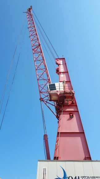
The International Archives of the Photogrammetry, Remote Sensing and Spatial Information Sciences, Volume XLIII-B2-2020, 2020
                                               XXIV ISPRS Congress (2020 edition)

 Figure 1. Closed route traversed in a counterclockwise direction overlaid on a Google street map. Start and end points are indicated
   with green and red pins, respectively. The inset image shows the antennas of the three u-blox receivers attached on the car used.

The surveyed HGRS87 coordinates of the junction GCPs are             method when the GCPs are not visible in the new location. The
expressed in meters and in our case were of the form (6042XX,        image in Fig. 3 (c) corresponds to a reference view from which
39115XX, 0). It is well-known that when performing geomet-           a reference pose is estimated with the projections of the shown
ric computations that involve coordinates whose absolute val-        GCPs. Figure 3 (b) was obtained after the crane performed a
ues are far from 1, it is recommended to improve conditioning        counterclockwise rotation of about 120◦ . Using the proposed
via suitable transformations, e.g. see (Förstner, Wrobel, 2016).     method, the camera pose for the image in Fig. 3 (b) was cal-
In our case, we subtracted (60000, 3900000, 0) from all GCP          culated from the movement of the u-blox receivers. Measure-
coordinates, effectively transforming them to have the former as     ments from all three u-blox receivers were used, however due
their origin; u-blox positions were also translated accordingly.     to the platform performing a 2D rotation only, two or even a
                                                                     single one would suffice. The frustums of the camera for the
At the beginning and end of each of the five crane revolutions,      two images were computed from their poses and are projected
an image of the quay with the GCPs visible was acquired. Cam-        on the quay’s plane in Fig. 3 (a). To quantitatively assess the
era poses were then estimated with (Lourakis, 2014) using the        accuracy of the pose estimated for Fig. 3 (b), the corners of the
translated 3D coordinates of the GCPs (all lying on the z =          five nearest concrete slabs on the quay’s surface were surveyed
0 plane) and their image projections, after distortion removal.      and the camera pose was estimated using them as GCPs. The
The average reprojection error corresponding to the inliers for      pose estimate obtained in this manner was then compared with
the estimated poses was in the order of 1.5–2.5 pixels. Using        that computed with the proposed method. The difference in
the image before the first revolution as reference, we combined      rotations using the aforementioned metric was 1◦ whereas the
its pose and the crane platform’s displacements with eq. (3) to      distance between the camera centers was 0.35m.
transform it to the poses of the remaining nine crane locations.
To compare the transformed rotations with those estimated from                            6. CONCLUSIONS
the GCPs, we used the metric arccos((trace(RT2 R1 ) − 1)/2)
that corresponds to the angle of rotation about a unit vector        This paper has presented a technique for continuously estimat-
that transfers R2 to R1 (Huynh, 2009). For translations, we          ing the full 6D pose of a pinhole camera mounted on a mobile
used the Euclidean distance of camera centers computed with          platform. It overcomes the need for incessant tracking of visual
eq. (4). We found that the average difference in rotation angles     features by estimating the camera pose at a reference location
was 0.49◦ (SD 0.28◦ ) and the average distance of camera cen-        only and then incorporating position measurements from three
ters 0.31m (SD 0.15m). Note that these differences incorporate       low-cost, multi-GNSS receivers attached on the platform to up-
several sources of error such as calibration, pose estimate and      date the camera pose as the platform moves. No special fix-
GNSS position inaccuracies, numerical round-off errors, etc.         tures or arrangements are required for the camera or the GNSS
                                                                     receivers. Experiments with two different setups have demon-
Figures 3 (b) and (c) illustrate an example of using the proposed    strated the effectiveness of the proposed solution.

                                                This contribution has been peer-reviewed.
                  https://doi.org/10.5194/isprs-archives-XLIII-B2-2020-55-2020 | © Authors 2020. CC BY 4.0 License.                59
The International Archives of the Photogrammetry, Remote Sensing and Spatial Information Sciences, Volume XLIII-B2-2020, 2020
XXIV ISPRS Congress (2020 edition)
Zoomed-in detail
(a)
(b)
Figure 2. Moving trihedrals for the 3D poses estimated for the route of Figure 1. A top view of the x, y plane is in (a) and a side view
towards the positive y-axis, demonstrating altitude differences, in (b). The inset image in (a) shows its lower left part in more detail.
ACKNOWLEDGEMENTS Fischler, M. A., Bolles, R. C., 1981. Random sample consensus:
a paradigm for model fitting with applications to image analysis
This work has been partially supported by the European Uni- and automated cartography. Commun. of the ACM, 24(6), 381–
on’s Horizon 2020 Research and Innovation programme under 395.
Grant Agreement No. 826506 (EU project sustAGE, https: Förstner, W., Wrobel, B. P., 2016. Photogrammetric Computer
//www.sustage.eu). We thank Evangelos Loutsetis for his Vision: Statistics, Geometry, Orientation and Reconstruction.
support with data acquisition and the Heraklion Port Authority Springer International Publishing, Cham.
for granting us quay and crane access. Fotiou, A., Pikridas, C., 2012. GPS and Geodetic Applications.
Second edn, Ziti Editions, ISBN: 978-960-456-346-3.
REFERENCES Fotiou, A., Pikridas, C., Rossikopoulos, D., Spatalas, S.,
Tsioukas, V., Katsougiannopoulos, S., 2009. The Hermes GNSS
Cavegn, S., Blaser, S., Nebiker, S., Haala, N., 2018. Robust and NtripCaster of AUTh. Bulletin of Geodesy and Geophysics.
accurate image-based georeferencing exploiting relative orienta-
tion constraints. ISPRS Ann. Photogramm. Remote Sens. Spatial Gabrlik, P., 2015. The Use of Direct Georeferencing in Aerial
Inf. Sci., IV-2, 57–64. Photogrammetry with Micro UAV. IFAC-PapersOnLine, 48(4),
380–385. 13th IFAC and IEEE Conference on Programmable
Cramer, M., Stallmann, D., Haala, N., 2001. Direct Georeferen- Devices and Embedded Systems.
cing Using GPS/Inertial Exterior Orientations for Photogrammet-
ric Applications. International Archives of Photogrammetry and Gao, X.-S., Hou, X.-R., Tang, J., Cheng, H.-F., 2003. Complete
Remote Sensing, 33. solution classification for the perspective-three-point problem.
This contribution has been peer-reviewed.
https://doi.org/10.5194/isprs-archives-XLIII-B2-2020-55-2020 | © Authors 2020. CC BY 4.0 License. 60The International Archives of the Photogrammetry, Remote Sensing and Spatial Information Sciences, Volume XLIII-B2-2020, 2020
XXIV ISPRS Congress (2020 edition)
IEEE Transactions on Pattern Analysis and Machine Intelligence, National Imagery and Mapping Agency, 2000. Department of de-
25(8), 930–943. fense world geodetic system 1984: its definition and relationships
Grunert, J., 1841. Das pothenotische Problem in erweiterter with local geodetic systems. Technical Report TR8350.2, NIMA,
Gestalt nebst über seine Anwendungen in Geodäsie. Grunerts St. Louis, MO, USA.
Archiv für Mathematik und Physik. Nebiker, S., Cavegn, S., Eugster, H., Laemmer, K., Markram, J.,
Grussenmeyer, P., Al Khalil, O., 2002. Solutions for Exterior Ori- Wagner, R., 2012. Fusion of airborne and terrestrial image-based
entation in Photogrammetry: A Review. The Photogrammetric 3D modelling for road infrastructure management - vision and
Record, 17(100), 615–634. first experiments. Proceedings of Int. Arch. Photogramm. Remote
Sens. Spatial Inf. Sci., 79–84.
Hackeloeer, A., Klasing, K., Krisp, J. M., Meng, L., 2014. Geor- O’Keefe, K., Lachapelle, G., 2007. Network Real-Time Kin-
eferencing: a review of methods and applications. Annals of GIS, ematic Performance Analysis Using RTCM 3.0 and the Southern
20(1), 61–69. Alberta Network. GEOMATICA, 61(1), 29–41.
Hartley, R., Zisserman, A., 2004. Multiple View Geometry in Pateraki, M., 2005. Adaptive multi-image matching algorithm
Computer Vision. Second edn, Cambridge University Press, for DSM generation from airborne linear array CCD data. PhD
ISBN: 0521540518. thesis, Diss. ETH Zurich, Nr. 15915, Institute of Geodesy and
Hays, J., Efros, A. A., 2008. IM2GPS: estimating geographic in- Photogrammetry, Mitteilung No. 86.
formation from a single image. IEEE Conference on Computer Regmi, K., Shah, M., 2019. Bridging the domain gap for ground-
Vision and Pattern Recognition, 1–8. to-aerial image matching. IEEE/CVF International Conference
Hesch, J. A., Roumeliotis, S. I., 2011. A direct least-squares on Computer Vision, 470–479.
(DLS) method for PnP. International Conference on Computer Rietdorf, A., Daub, C., Loef, P., 2006. Precise positioning in real-
Vision, IEEE, 383–390. time using navigation satellites and telecommunication. Proceed-
Horn, B. K. P., 1987. Closed-form Solution of Absolute Orient- ings of the 3rd Workshop on Positioning, Navigation and Commu-
ation Using Unit Quaternions. J. Optical Society of America A, nication.
4(4), 629–642. Sakoe, H., Chiba, S., 1978. Dynamic programming algorithm op-
Hourdakis, E., Lourakis, M., 2015. Countering drift in visual timization for spoken word recognition. IEEE Transactions on
odometry for planetary rovers by registering boulders in ground Acoustics, Speech, and Signal Processing, 26(1), 43–49.
and orbital images. IEEE/RSJ International Conference on Intel- Schönberger, J. L., Frahm, J.-M., 2016. Structure-from-motion
ligent Robots and Systems (IROS), 111–116. revisited. Proceedings of the IEEE Conference on Computer Vis-
Huynh, D. Q., 2009. Metrics for 3D Rotations: Comparison and ion and Pattern Recognition, 4104–4113.
Analysis. J. Math. Imaging Vis., 35(2), 155–164. Shan, Q., Wu, C., Curless, B., Furukawa, Y., Hernandez, C.,
Seitz, S. M., 2014. Accurate geo-registration by ground-to-aerial
Jende, P., Nex, F., Gerke, M., Vosselman, G., 2017. Fully auto-
image matching. International Conference on 3D Vision, 1, 525–
matic feature-based registration of mobile mapping and aerial
532.
nadir images for enabling the adjustment of mobile platform loc-
ations in GNSS-denied urban environments. Proceedings of IS- Snavely, N., Seitz, S. M., Szeliski, R., 2008. Modeling the World
PRS Hannover Workshop: HRIGI 17 – CMRT 17 – ISA 17 – from Internet Photo Collections. International Journal of Com-
EuroCOW 17, ISPRS Archives, 317–323. puter Vision, 80(2), 189–210.
Jensen, A., Cannon, M., 2000. Performance of network RTK us- U-blox, 2020. ZED-F9P module. https://www.u-blox.com/
ing fixed and float ambiguities. Proceedings of the National Tech- en/product/zed-f9p-module. (8 Apr. 2020).
nical Meeting of the Institute of Navigation, Institute of Naviga- Umeyama, S., 1991. Least-squares Estimation of Transformation
tion, 797–805. Parameters Between Two Point Patterns. IEEE Transactions on
Li, Y., Snavely, N., Huttenlocher, D., Fua, P., 2012. Worldwide Pattern Analysis and Machine Intelligence, 13(4), 376–380.
pose estimation using 3D point clouds. European Conference on Upton, E., Halfacree, G., 2016. Raspberry Pi User Guide. 4th
Computer Vision, I, Springer-Verlag, Berlin, Heidelberg, 15–29. edn, Wiley Publishing.
Liebowitz, D., Zisserman, A., 1998. Metric rectification for per- Veis, G., Paradissis, D., 1990. GPS activities for geodesy and
spective images of planes. IEEE Conference on Computer Vision geodynamics in Greece. 2nd GPS Conference, Ottawa.
and Pattern Recognition, 482–488. Weber, G., Dettmering, D., Gebhard, H., 2005. Networked trans-
Lin, T.-Y., Belongie, S., Hays, J., 2013. Cross-view image geo- port of RTCM via Internet Protocol (NTRIP). F. Sansò (ed.), A
localization. IEEE Conference on Computer Vision and Pattern Window on the Future of Geodesy, Springer Berlin Heidelberg,
Recognition, 891–898. 60–64.
Westoby, M., Brasington, J., Glasser, N., Hambrey, M., Reynolds,
Lourakis, M., 2014. posest : A C/C++ library for robust 6DoF J., 2012. ‘Structure-from-Motion’ photogrammetry: A low-cost,
pose estimation from 3D-2D correspondences. (8 Apr. 2020). effective tool for geoscience applications. Geomorphology, 179,
Lourakis, M., Terzakis, G., 2018. Efficient absolute orientation 300–314.
revisited. Proceedings of the IEEE/RSJ International Conference Wildes, R. P., Hirvonen, D. J., Hsu, S. C., Kumar, R., Lehman,
on Intelligent Robots and Systems (IROS), 5813–5818. W. B., Matei, B., Zhao, W. ., 2001. Video georegistration: al-
Lourakis, M., Terzakis, G., 2020. A globally optimal method for gorithm and quantitative evaluation. IEEE International Confer-
the PnP problem with MRP rotation parameterization. Submitted ence on Computer Vision, 2, 343–350.
to the International Conference on Pattern Recognition. Zamir, A. R., Hakeem, A., Van Gool, L., Shah, M., Szeliski,
Lourakis, M., Zabulis, X., 2013a. Accurate scale factor estima- R., 2016. Introduction to Large-Scale Visual Geo-localization.
tion in 3D reconstruction. Computer Analysis of Images and Pat- Springer International Publishing, Cham, 1–18.
terns, Springer Berlin Heidelberg, 498–506. Zhang, W., Kosecka, J., 2006. Image based localization in urban
Lourakis, M., Zabulis, X., 2013b. Model-based pose estimation environments. Third Int’l Symposium on 3D Data Processing,
for rigid objects. International Conference on Computer Vision Visualization, and Transmission (3DPVT’06), 33–40.
Systems, Springer, 83–92. Zhang, Z., 2000. A Flexible New Technique for Camera Calibra-
Mills, D. L., 1991. Internet time synchronization: the network tion. IEEE Transactions on Pattern Analysis and Machine Intel-
time protocol. IEEE Transactions on Communications, 39(10), ligence, 22(11), 1330–1334.
1482-1493. Zheng, Y., Kuang, Y., Sugimoto, S., Åström, K., Okutomi, M.,
Nakano, G., 2015. Globally optimal DLS method for PnP prob- 2013. Revisiting the PnP problem: A fast, general and optimal
lem with Cayley parameterization. British Machine Vision Con- solution. Proceedings of the IEEE International Conference on
ference, 78.1–78.11. Computer Vision, 2344–2351.
This contribution has been peer-reviewed.
https://doi.org/10.5194/isprs-archives-XLIII-B2-2020-55-2020 | © Authors 2020. CC BY 4.0 License. 61The International Archives of the Photogrammetry, Remote Sensing and Spatial Information Sciences, Volume XLIII-B2-2020, 2020
XXIV ISPRS Congress (2020 edition)
(a)
(b) (c)
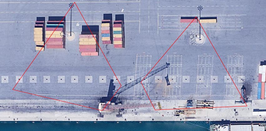
Figure 3. (a) Non-orthorectified satellite view of the port quay with the crane in the bottom middle and the inset image. The two red
quadrangles correspond to the intersections of the quay’s plane with the camera frustums of the images in (b) and (c) [the position of
the crane shown in image (a) does not coincide with that from which images (b), (c) were taken]. (b), (c) Views of the quay from the
camera installed on the crane. The image in (c) was obtained from the reference location and has the employed GCPs superimposed.
The four extremal junctions used for the world to image homography estimation are GCPs 1, 5, 26 and 30. Image (b) is a view from
the camera after the crane has rotated about 120◦ in a counterclockwise direction. The GCPs shown are used for pose verification.
This contribution has been peer-reviewed.
https://doi.org/10.5194/isprs-archives-XLIII-B2-2020-55-2020 | © Authors 2020. CC BY 4.0 License. 62You can also read