Introducing UAS and Photogrammetry for Surveying and Surveilling New Project Sites - Simon Syring Joel Nylund Degree Thesis for Bachelor of ...
←
→
Page content transcription
If your browser does not render page correctly, please read the page content below
Introducing UAS and
Photogrammetry for Surveying
and Surveilling New Project Sites

Simon Syring

Joel Nylund

Degree Thesis for Bachelor of Engineering

Degree programme in Land Surveying

Vasa 2018
EXAMENSARBETE

Författare: Joel Nylund & Simon Syring
Utbildning och ort: Lantmäteriteknik, Vasa
Handledare: Sem Timmerbacka

Titel:
Introducering av UAS och fotogrammetri för övervakning och undersökning av nya projekt

_________________________________________________________________________
Datum 9.4.2018    Sidantal 35  Bilagor 4
_________________________________________________________________________
Abstrakt
Detta lärdomsprov är gjort åt ett finskt storföretag inom energi och byggbranschen.
Huvudsyftet med detta lärdomsprov var att optimera övervakningen och dokumentering
av pågående byggprojekt med hjälp av drönare och fotogrammetri. Lärdomsprovet är
indelat i tre delar; teoridel, analysdel och en resultatdel. Målet var att finna den mest
användarvänliga drönar och program uppsättning som kan ge tillräckligt goda och
pålitliga resultat.

I teoridelen beskrivs de olika faktorer som gör fotogrammetriska mätningar möjliga samt
en jämförelse mellan olika drönare, mjukvaruprogram och dess egenskaper.
Till examensarbetet valdes en drönare vars teoretiska egenskaper skulle möta våra krav.
Denna drönare införskaffades och sattes till prov. Senare kunde vi pröva olika
mjukvaruprogram för vidare hantering av det insamlade materialet, detta beskrivs i
analysdelen.

Vårt resultat blev en kartläggning av olika mjukvaruprogram och förslag till ett system
inkluderat drönare, mjukvaruprogram för datahantering och flygruttsplanering.
_________________________________________________________________________
Språk: engelska       Nyckelord: UAS, fotogrammetri, mjukvara, dokumentation
_________________________________________________________________________
OPINNÄYTETYÖ

Tekijät: Joel Nylund & Simon Syring
Koulutus ja paikkakunta: Maanmittaustekniikka, Vaasa
Ohjaaja: Sem Timmerbacka

Nimike:
UAS:n ja fotogrammetrian käyttöönotto uusien projektien tutkimuksessa ja valvonnassa
_________________________________________________________________________
Päivämäärä 9.4.2018   Sivumäärä 35   Liitteet 4
_________________________________________________________________________
Tiivistelmä
Tämä opinnäytetyö on tehty suomalaiselle energia- ja rakennusalan yritykselle.
Opinnäytetyön päätavoite oli meneillään olevan projektin valvonnan optimointi dronen
ja fotogrammetrian avulla. Opinnäytetyö on kolmiosainen; teoriaosa, analyysiosa ja
tulososa. Tavoite oli löytää käyttäjäystävällisin järjestelmä, joka voi antaa riittävän hyvän
ja luotettavan tuloksen.

Teoriaosassa esitellään eri tekijöitä, jotka tekevät fotogrammetriset mittaukset
mahdollisiksi. Tehtiin myös vertailu eri dronien, ohjelmien ja niiden ominaisuuksien
välillä.
Lopputyöhön valittiin drone, jonka ominaisuudet vastasivat meidän vaatimuksiamme.
Drone hankittiin ja sitä käytettiin. Myöhemmin kokeiltiin eri ohjelmia kerätyn materiaalin
jatkokäsittelyä varten. Tästä kerrotaan enemmän analyysiosassa.

Tuloksena saimme kartoituksen eri ohjelmista ja ehdotuksen järjestelmästä, joka sisältää
dronen sekä ohjelmiston datakäsittelyyn ja lentoreittisuunnitteluun.
_________________________________________________________________________
Kieli: englanti       Avainsanat: UAS, fotogrammetria, software, dokumentaatio
_________________________________________________________________________
BACHELOR’S THESIS

Authors: Joel Nylund & Simon Syring
Degree Programme: Land Surveying, Vasa
Supervisor: Sem Timmerbacka

Title:
Introducing UAS and Photogrammetry for Surveying and Surveilling New Project Sites
_________________________________________________________________________
Date April 4, 2018 Number of pages 35   Appendices     4
_________________________________________________________________________
Abstract
This bachelor’s thesis was made for a Finnish energy and construction company.
The main purpose with this thesis was to optimize surveillance of on-going projects with
the help of a drone and photogrammetry. The thesis is divided into three parts; theory,
analysis and results. The goal was to find the most user-friendly drone and software set
that can give results that are reliable and good enough.

In the theoretical part we describe the different factors that make photogrammetric
measurements possible along with a comparison between drones, software and its
qualities. A drone whose theoretical specifications would match our demands was
chosen, procured and put to test. Later we tried different software for managing the
collected data, this is described in the analysis part.

Our result became a survey of different software and a suggestion to a system including
a drone and a software for data management and route-planning.

_________________________________________________________________________
Language: English     Key words: UAS, photogrammetry, software, documentation
_________________________________________________________________________
Content
1     Introduction ....................................................................................................................................... 3
    1.1       Problem ........................................................................................................................................ 3
    1.2       Purpose ........................................................................................................................................ 3
    1.3       Limitations .................................................................................................................................. 3
2     Photogrammetry .............................................................................................................................. 4
    2.1       Measuring with photogrammetry ...................................................................................... 4
    2.2       Products of photogrammetry .............................................................................................. 4
    2.3       Photogrammetry with UAV taken images ...................................................................... 5
3     UAV ........................................................................................................................................................ 5
    3.1       Quadcopter ................................................................................................................................. 5
      3.1.1           DJI Phantom 4 Pro ........................................................................................................... 6
      3.1.2           DJI Mavic Pro ..................................................................................................................... 7
      3.1.3           DJI Matrice 200 series .................................................................................................... 7
    3.2       Fixed wing ................................................................................................................................... 8
4     Positioning system ........................................................................................................................... 8
    4.1       GNSS .............................................................................................................................................. 8
    4.2       RTK................................................................................................................................................. 9
    4.3       Ground control points ......................................................................................................... 10
5     Camera parameters ...................................................................................................................... 11
    5.1       Gimbal ........................................................................................................................................ 11
    5.2       Internal and external orientation ................................................................................... 12
      5.2.1           Interior orientation ...................................................................................................... 12
      5.2.2           Exterior orientation ..................................................................................................... 13
6     Autopilot software ........................................................................................................................ 13
    6.1       Pix 4D ......................................................................................................................................... 13
    6.2       Dronedeploy ............................................................................................................................ 15
    6.3       UgCS ............................................................................................................................................ 16
7     Choice of camera............................................................................................................................ 17
8     Time of flight ................................................................................................................................... 18
9     Flight permits and regulations for drones........................................................................... 19
10        Test flights .................................................................................................................................... 20
    10.1          Preparations........................................................................................................................ 20
    10.2          Test areas ............................................................................................................................. 23
    10.3          Weekly flights ..................................................................................................................... 24
    10.4          Weather conditions .......................................................................................................... 24
11        Software for data ....................................................................................................................... 25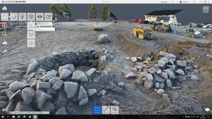
11.1 Agisoft Photoscan.............................................................................................................. 25
11.2 Pix 4D ..................................................................................................................................... 26
11.3 Autodesk ............................................................................................................................... 27
11.4 Dronedeploy ....................................................................................................................... 28
12 Results ............................................................................................................................................ 29
12.1 Orthomosaic ........................................................................................................................ 29
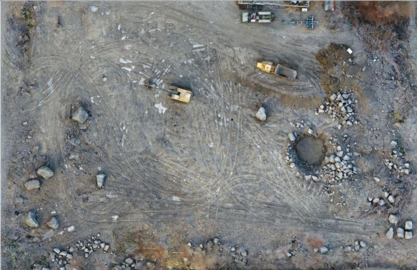
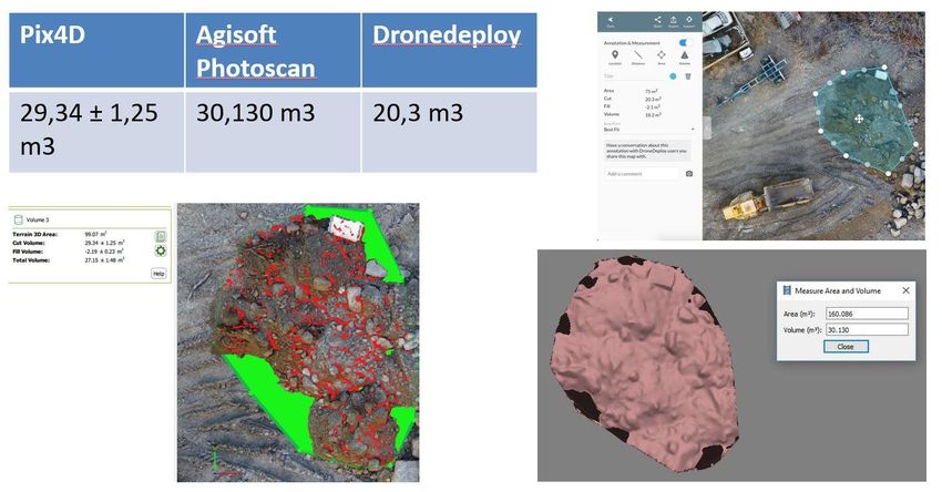
12.2 Volume calculations ......................................................................................................... 32
12.2.1 Dronedeploy ............................................................................................................... 32
12.2.2 Pix4D ............................................................................................................................. 33
12.2.3 Agisoft Photoscan ..................................................................................................... 33
12.2.4 Autodesk ...................................................................................................................... 33
12.2.5 Comparison................................................................................................................. 34
12.3 Point cloud ........................................................................................................................... 34
12.3.1 Comparison................................................................................................................. 35
13 Processing hardware ................................................................................................................ 37
14 Discussion ..................................................................................................................................... 38
14.1 Comments ............................................................................................................................ 38
14.2 Further research................................................................................................................ 38
14.3 Final conclusion ................................................................................................................. 39
15 References .................................................................................................................................... 40
15.1 Figures ................................................................................................................................... 42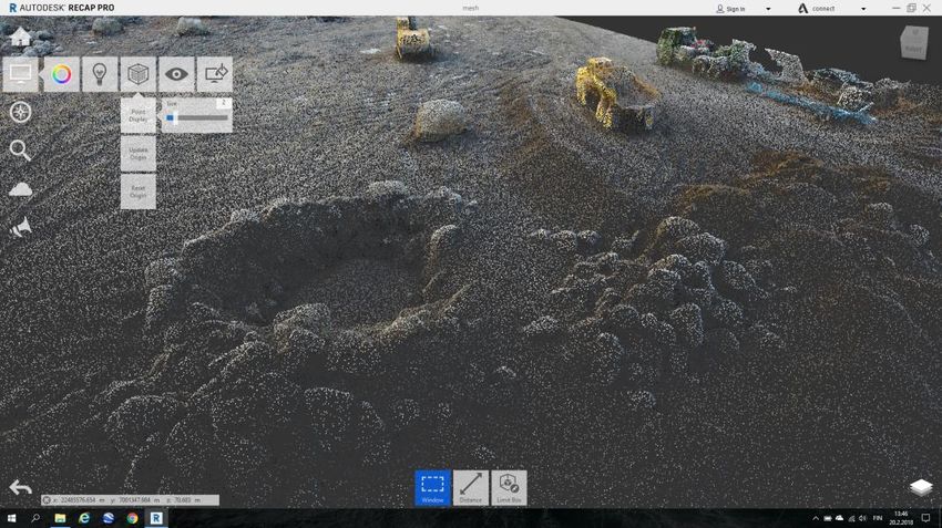
1

List of figures

Figure 1.DJI: Quadcopter......................................................................................................................... 6
Figure 2. Remote control for a quadcopter ...................................................................................... 6
Figure 3. DJI: DJI Phantom 4 Pro .......................................................................................................... 6
Figure 4. DJI: DJI Mavic Pro .................................................................................................................... 7
Figure 5. DJI: DJI Matrice 200 ................................................................................................................ 7
Figure 6. Sensefly: Sensefly eBee Plus ............................................................................................... 8
Figure 7. Satellite positioning principle ............................................................................................ 9
Figure 8. RTK positioning .................................................................................................................... 10
Figure 9. Single point positioning ..................................................................................................... 10
Figure 10. Signal seen from 50 m above ........................................................................................ 10
Figure 11. GCP Plate (40x40 cm) ...................................................................................................... 10
Figure 12. Gimbal .................................................................................................................................... 11
Figure 13.internal and external geometry .................................................................................... 12
Figure 14. Pix 4D Ctrl + DJI application interface....................................................................... 14
Figure 15. Pix 4D, different mission planning options ............................................................. 14
Figure 16. Pix 4D, double grid mission ........................................................................................... 14
Figure 17. Dronedeploy interface and planning ......................................................................... 15
Figure 18. UgCS interface ..................................................................................................................... 16
Figure 19. Ground sample distance ................................................................................................. 17
Figure 20. GSD calculator..................................................................................................................... 20
Figure 21. Pix4D user interface ......................................................................................................... 21
Figure 22. Drone-bag and content.................................................................................................... 22
Figure 23. GCP from above .................................................................................................................. 22
Figure 24. Measuring GCP ................................................................................................................... 22
Figure 25. Pre construction site ........................................................................................................ 23
Figure 26. Skeppsparken ..................................................................................................................... 23
Figure 27. Building permanent GCP ................................................................................................ 24
Figure 28. Removing ice for GCP ....................................................................................................... 24
Figure 29. Quality report ..................................................................................................................... 29
Figure 30. Ortomosaic from 26.01.2018 ........................................................................................ 31
Figure 31. Ortomosaic from 15.11.2017 ........................................................................................ 31
Figure 32. Dronedeploy volume calculation ................................................................................ 32
Figure 33. Volume calculations ......................................................................................................... 34
Figure 34. Agisoft pointcloud ............................................................................................................. 35
Figure 35. Recap pointcloud ............................................................................................................... 35
Figure 36. Point amount differences ............................................................................................... 36
Figure 37. Difference between pointclouds.................................................................................. 36
2

Definitions
Photogrammetry: The process of making measurements from photographs, used esp. in the
construction of maps from aerial photographs (Dictionay.com)

UAS: Unmanned aerial system

UAV: Unmanned aerial vehicle

GCP: Ground control point

GSD: Ground sampling distance

RTK: Real time kinematic

GNSS: Global navigation satellite system

KML: Keyhole markup language, a file format to display geographic data in an earth
browser such as google earth.
3

1 Introduction
This thesis became reality after contacting our client and asked if they could have any use of
mapping and scanning their project sites for documenting. After a meeting with our
supervisor from Novia, Sem Timmerbacka and our contact person Simon Nyman, we came
to the conclusion that photogrammetry with UAVs could be a cheap and moneysaving
solution. After we had our first results we showed them to our client who was represented
by Simon Nyman and Markus Sandås. At the meeting, all kinds of applications were
discussed how they could benefit from this solution and resulted in further investigation
beside the thesis.

1.1 Problem

The main problem that later became the main goal for this thesis, was to show how a drone
and photogrammetry could change the way projects were documented and supervised. This
because of the problems that before had occurred when contractors not fulfilling deadlines
and mass change volumes not adding up. Nowadays there is no documentation that could
prove the contractors wrong. With our solution these problems could be avoided and save a
lot of time and money with a relatively cheap solution.

1.2 Purpose

Our final purpose for this thesis was firstly to do an introduction on how it works and then
practically try it with a drone. This resulted in a try-out between different software regarding
route-planning and photogrammetric processing to see which one would be the best fit for
our client. Then showing the results and workflow from our tests, and also come up with
other implementations with the same setup.

1.3 Limitations
The thesis was limited to a point where we were asked to try the method out on a real project
and how it would be realized. From here the client would not want anything more of our
progress described in this thesis.
4

2 Photogrammetry
Photogrammetry comes from three Greek words; phos or phot, gamma and metrein.
Translated they mean light, something drawn, and measure (T.Schenk, 2005).
Photogrammetry explained, is when you through measuring and interpretation from one or
several pictures can decide and document position, shapes and other characteristics from the
objects pictured (Lantmäteriet m.fl, 2013).

2.1 Measuring with photogrammetry

The requirements of making measurements with photogrammetry is to have image pairs or
block pictures that is overlapping each other and showing the object from different
directions. With these pictures it is possible to calculate the three-dimensional coordinates
and the coordinates together will form a numeric model. This process is nowadays computer
based and require a very powerful computer with great memory and effective software.
(Lantmäteriet, 2013)

2.2 Products of photogrammetry

Photogrammetry is mainly used to produce all kinds of maps, such as maps for government
planning and orienteering. Photogrammetry is also used in architectural needs, car industries,
and forensics. These kinds of photogrammetry are called terrestrial-photogrammetry
(Lantmäteriet, 2013).

Geodetic Systems Inc. (GSI) is one of the world leading provider of high accuracy automated
photogrammetric systems. The systems that they are providing, are used in industries like
aircraft, automobile, and shipbuilding with an accuracy reaching up to 0.020 mm at 4 m.
Implements are escalating while the drone is getting cheaper and better. For an example, an
article in The Guardian written by Katie Fehrenbacher (2017) describes how solar power
developers uses drones to design solar plants 90% faster. Also, when the solar projects are
done, flights are performed with infrared cameras fastened to the drone. The images from
the infrared camera can reveal which panels are not producing electricity.
5
2.3 Photogrammetry with UAV taken images

When using photogrammetry with UAV taken images you fly in straight lines to get a block
of images. These images have to overlap at least 60% of each another to be able to use them
in the image recognition process and calculations. The process of calculating points with
photogrammetry comes down to triangulation therefore at least two images are needed. With
the two images, we are able to make rays from the camera positions, to the points in the
terrain imaged. (Lantmäteriet, 2013) The camera positions from UAVs are often stored with
the picture as metadata. The metadata will allow a faster processing regarding on how much
and what kind of metadata the system stores.

3 UAV
Unmanned aerial vehicle, UAVs are common in the photogrammetry industry. There are
many different types of UAVs, in this chapter we will talk about the most common types
used in small-format aerial photogrammetry; Quadcopters and Wing planes.

UAVs can be controlled by a pilot on the ground controlling the vehicle while having visual
contact with it. Nowadays it is easier and more effective to use an autopilot software, where
you plan the route of the flight on the application on your computer or mobile device. The
autopilot application allows you to choose speed, the height of the flight, how much overlap
you want on the photos and how fast you want the vehicle to fly.

Before the invention of autopilot applications, the vehicles were remote-controlled, requiring
a pilot with a lot of experience. The main problem with manual control is to navigate the
plane to the exact location as predefined, and even more difficult if the camera does not have
a remote trigger, making the camera take photos in unwanted positions. (James S aber, 2010)

3.1 Quadcopter

A Quadcopter is an aerial vehicle that has four rotors placed horizontally in a square
formation with each rotor placed with equal distance from the center of mass of the copter.
The rotors facing each other rotates the same way i.e. two rotors rotate to the left and the
other two rotates to the right, this makes the quadcopter easy to maneuver and stabile.
Quadcopters are used in many different areas and have gained much interest in the 21st
century. Quadcopters comes in many different sizes, the smallest ones without a camera can
be under 10 cm between the rotors wingtips, and the biggest ones can be up to 2 m. The
6
Quadcopter is remotely controlled from the ground with radio signals or Bluetooth.
(Luukkonen, 2011). Because of the ability to hover, and to be able to fly very slowly, we
decided that a quadcopter would fit our needs better than a wingplane. There are many
different drone manufacturers, but the world-leading company today is DJI, that is why we
chose to compare and try one of their drones. Below we have listed three different DJI
quadcopters that could fit our needs.

                                                       Figure 2. Remote control for a quadcopter
  Figure 1,DJI: Quadcopter

3.1.1 DJI Phantom 4 Pro

The DJI Phantom 4 is DJIs most popular drone, the Pro model is the most expensive Phantom
model, right now. The Phantom 4 Pro comes with an onboard camera, equipped with a 1
inch sensor and 20 megapixels. (DJI, 2018)

The Phantom 4 Pro is a medium size drone, mostly used by persons who has drones as their
hobby. But it can also be used in professional purpose. Because of the price and
specifications, and the fact that our taskmaster already had one of these at a site, we decided
to try this model for our test flights.

                                          Figure 3. DJI: DJI Phantom 4 Pro
7
3.1.2 DJI Mavic Pro
The DJI Mavic Pro is a smaller sized and a cheaper drone compared to Phantom 4 Pro, with
foldable propellers and arms it makes the Mavic easy to travel with which is appreciated by
hobby-consumers. But for our needs, the camera specifications did not fulfill our needs. (DJI,
2018)
Figure 4. DJI: DJI Mavic Pro
Figure 5. DJI: DJI Matrice 200
3.1.3 DJI Matrice 200 series
The DJI Matrice 200 series is DJIs professional enterprise series, built to ensure stable flights
in strong winds and water resistant. The Matrice series does not come with any camera, so
you need to buy the camera separately, which makes the installation process more difficult
compared to the Mavic and Phantom. The positive side of choosing your own camera is that
you can choose the camera that fits your needs. (DJI, 2018)
Model Phantom 4 Pro Mavic Pro Matrice 200 (TB55)
Weight 1388g 734g 4530g
Max flight time 30 min 27 min 38 min
Max wind speed resistance 10 m/s 10 m/s 12 m/s
Size, unfolded 350 mm 83x83x198 mm 887×880×378 mm
Sensor 1” CMOS, 20 megapixels 1 /2.3” CMOS 12.35 mega -
Lens FOV 84°, 8.8mm/24mm FOV 78.8°, 28mm -
f-number F/2.8-F/11 F/2.2 -
Electronic shutter speed 8-1/8000 s 8-1/8000 s -
Operating Temperature Range 0°- 40°C 0° - 40°C -20° - 40°C
Waterproof NO NO YES
Price (USD $) 1499 999 ⁓ 4000
Chart 1, Drone specifications8
3.2 Fixed wing
Fixed wing drones works like a normal aeroplane, using wings to provide the lift and use the
energy from the motor to move forward. This makes the drone very energy efficient, and is
therefore able to map larger areas, fly longer distances compared to a multi-rotor copter.
But there are many downsides of a fixed
wing drone, the inability to hover makes
it difficult to begin the flight, you either
have to use a catapult or a runway. The
flight speed is also much faster, this can
make the photos blurry. Depending on
size, you have to land them on a runway,
use a parachute or catch them in a net.
Fixed wing drones are also a lot more
Figure 6. Sensefly: Sensefly eBee Plus
expensive than smaller multi-rotor
drones. (Australian UAV, 2016)
4 Positioning system
UAVs that are used for photogrammetry these days has some sort of positioning system,
without a positioning system the autopilot would not work. Most of the smaller and cheaper
UAVs as the DJI Phantom 4 pro and DJI Mavic pro, uses one satellite receiver, just like a
smartphone. This makes flying in autopilot possible, but the precision is not so accurate
compared to the DJI Matrice 210 RTK that has 2 big receivers, which makes the positioning
system much more accurate. (DJI, 2018)
4.1 GNSS
The American GPS (Global Positioning System), the Russian GLONASS (GLobal
NAvigation Satellite System), the European GALILEO and the Chinese COMPASS are all
different satellite positioning systems. These systems go under the name GNSS (Global
Navigation Satellite Systems)9
The GNSS-system is used worldwide on a daily basis, by almost everyone. For example
everyone that has a smartphone uses the GNSS-system. Receivers in the phone, or drone in
our case, measures the distance |ρ| to available satellites, or actually the time it takes for the
signal to reach the receiver from the satellite. Every satellite has its own parameters, and its
coordinates ρS can be calculated. The receivers coordinates ρM can be calculated by solving
the equation |ρ|=|ρS - ρM|. This method is called Single Point Positioning. (Horemuz, 2013)
Satellitecourse
Satellite
receiver
Surface of earth
Center of earth
Figure 7. Satellite positioning principle
4.2 RTK
Real Time Kinematic, this method is a more accurate method than “Single Point
Positioning”. With real time kinematic you use one, or many reference stations that sends
RTK-corrections to one, or many moving receivers placed on the object, a drone in this case.
This is a pretty simple solution to get good positioning, the disadvantage with this method
is that you got to have access to a reference receiver and knowledge on how to handle it.
(Horemuz, 2013)10 Figure 9. Single point positioning Figure 8. RTK positioning 4.3 Ground control points Usually in photogrammetry projects you use GCPs, ground control points. GCPs are signals that are placed out within the area that you are photographing. There are different kinds of signals but usually it is a flat plate with some sort of cross or point on it. The signals are measured by hand with a portable GNSS receiver or a total station, giving the signals accurate coordinates. The size of the signals depends on the height of the flight and what camera you use. The signals are placed inside the mapping area in each corner and if the area is big you can place one in the middle also. Later in the processing phase, you mark the signals on the photos, this is used to rotate, rescale and fit the images to the same coordinate system as the ground control points. (James S aber, 2010) Figure 11. GCP Plate (40x40 cm) Figure 10. Signal seen from 50m above
11

5 Camera parameters
In this chapter we will look at the camera parameters, and what they are for. This shows how
aerial photogrammetry is theoretically possible. We will look at the inner geometry of the
camera, internal and external orientation and also the mount for the camera on drones, the
gimbal. The gimbal is used for drones to ease the capturing moment.

5.1 Gimbal

Another word for gimbal that explains it better would be a “three axis camera mount”. The
three axis consists of yaw, roll, pitch. These three axis determines how the camera is aimed
(Johansson, 2012).

Figure 12. Gimbal

A gimbal is crucial for a drone as it removes vibration from the propeller and flight motors.
It also allows the camera to stabilize and focus on the object while the drone itself is
compensating for wind.

When dealing with gimbal for drones there are two alternatives, buy a separate camera for
the gimbal, or a drone with camera integrated with the gimbal. The first option is more
favored by the professionals because of the ability to make more adjustments with a separate
camera and also to choose the camera itself for the drone.
12
The consumer gimbal came available around 2012. The reason has been the developing of
MEMS (Micro-Electro-Mechanical-Systems). More specific for a drone MEMS are IMU
(Inertial Measurement units), Accelerometers and Gyroscopes. These parts are translating
mechanical forces to an electronic signal which can be fed into a computer. (Droneflyers,
2015)

5.2 Internal and external orientation

Calculating precise 3D-coordinates with photogrammetry requires to reconstruct the
geometry within and outside of the camera. Reconstruction of the geometry is done with the
cameras internal and external orientation. Resulting in rays that creates a point cloud. Figure
13 shows an overview of the geometry. (James S aber, 2010, p. 26)

Figure 13. Internal and external geometry

5.2.1 Interior orientation

The elements of the interior orientation consist of the focal length measured at infinity,
position of the principal point o (Figure 13) and the parameters of radial lens distortion. In
the digital camera, the principal point is defined as pixel cell array of the sensor, for other
cameras such as metric analog cameras for example, field marks are used instead to realize
measurements in the image. Various calibrations can be used to determine the interior
orientation values. Metric cameras are often calibrated by the manufacturer and a calibration
13 report is given with the camera. (James S aber, 2010). For the small drones like DJI Phantom 4 no calibration report is given. They do provide the user with self-calibration methods with the help of their software DJI assistant. 5.2.2 Exterior orientation The exterior orientation includes X, Y, Z position and ,, rotation parameters for the camera. Nowadays small drones have this option of collecting these data but due to the cost of high-tech GPS/INS system and weight the result will suffer from insufficient precision. This is why GCPs are used for a more accurate result, as the GCPs are measured with a more accurate method determining position. The data collected from the drone may be used but can affect the result and make it more inaccurate. (James S aber, 2010) 6 Autopilot software There is many different autopilot software on the market, they all offer pretty much the same kind of autopilot system. The system allows you to choose the preferred height of the flight, how much overlap you want and how fast you want the drone to fly. The application takes control over the drone and you just have to power on the drone and push a single button, then it will fly the route as planned by itself. There is still some diversity in some software that we will compare. 6.1 Pix 4D As mentioned earlier Pix 4D also offers the autopilot application for your smartphone or tablet. The route-planning application Pix 4D Capture has a very simple and easy to use interface. You start by choosing what kind of map you want to do, if the mapping area is the shape of a polygon i.e. an area that is not the shape of a square, you can choose the polygon mission. If you have a square area you can choose grid mission. These two options are preferred if you want to do 2D maps, but it can also be processed to 3D maps, since you can choose the overlap to 90%. If you want to be sure you have enough footage for a good 3D map you can simply choose the double grid mission. If you are going to do a 3D model of an object, for example a building, you can choose the circular mission, this means the drone flies around the object taking photos from different angles and heights.
14
The negative side with Pix
4Ds autopilot software is that
you got to have two different
applications on your device,
Pix 4D capture and Ctrl +
DJI. In Capture you plan the
mission, but to get access to
the drone you need to go via
the Ctrl + DJI application.
Figure 14. Pix 4D Ctrl + DJI application interface What is very positive with Pix
4D, is that their autopilot
software is free to use, it is
only the access to the desktop
application Pix 4D Mapper
you need the license. So, you
can plan and fly the route for
free but you need the license
to process the data.
Figure 15. Pix 4D, different mission planning options
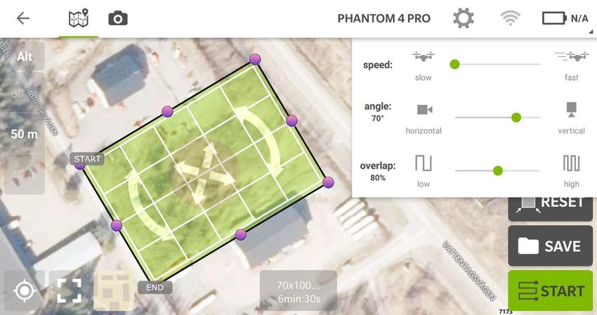
Figure 16. Pix 4D, double grid mission15 6.2 Dronedeploy Dronedeploy offers a very easy to use route planning and auto piloting option similar to Pix4d. Here a tablet or smartphone is preferred when flying. The app uses google maps as underlay so the user is also able to search for the area of interest by address or importing a KML file for planning. A box is predefined and its corners have to be stretched to the right area. Then the overlap, flight speed and altitude has to be determined. After all the settings for the flight is done, the mission is saved and the user is also given the alternative to save it in offline mode so it is possible to see the underlay properly without an internet connection. Figure 17. Dronedeploy interface and planning When arriving to the field and you are connected to the drone, no other application has to be used than Dronedeploys own app. Before flight, the app checks the GPS, camera, drone state and compass before giving green marks to set it fly autonomous. After the flight, you can directly upload the pictures for processing on Dronedeploy or extracting them from the drones SD-card. The positive thing about Dronedeploy, is that you are able to plan the mission on your office computer and then open it on your tablet or smartphone. The negative side would be the few settings you are able to choose between and not optimizing the flight direction by itself.
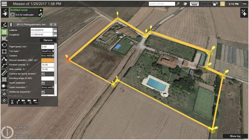
16
6.3 UgCS

UgCS is another software that offers auto piloting and route-planning. They offer many
different kinds of route-planning options depending on what kind of mission you intend to
execute. Like all the earlier software applications you are allowed to choose the altitude,
speed and camera angle, but in UgCS it is more precise, you can choose the altitude on a cm
level, and speed in 0,1 m/s precision. And in the route-planning you have more options, you
can choose different altitudes on different waypoints, different speed and so on.

UgCS offers route-planning missions for “normal” 2D and 3D maps, but also plans for low
altitude missions, solar panel inspection and powerline inspections.

UgCS is a great software for the professional users, you can also fly with many drones at the
same time to save time. But there are some negative sides as well, for example, you can not
plan the route on a smartphone or tablet, you must have your computer and the desktop
application running. This also means that you always have to bring your computer to the
flight area instead of just your mobile device.

Figure 18. UgCS interface
17

7 Choice of camera
To maintain high accuracy in photogrammetric measurements you will have to have a
camera taking photographs of the highest quality. The camera considerations are following;
field of view, focusing and exposure.

The cameras field of view is how wide the photos will be. The larger field of view will give
you less photos but a heavier camera, as the field of view is based on how big sensor and
lens you are using.

To take sharp photos it is necessary to focus the lens right. This is called depth of focus and
is a product of factors as; focal length, sensor size, distance from camera and the f-number.

Exposure is how much light the sensor is being exposed to. This is managed by how fast the
photo is being taken, shutter speed and how wide the aperture opens, also called f-number
(Geodetic, 2017).

When adding the camera to the drone a thumb rule is heavier cameras provide better results
but require a flying platform with a higher payload.

Knowing the accuracy demands on the end product will decide what kind of camera is
needed. An equation that calculates GSD (ground sample distance) can, before testing say
what kind of accuracy the camera theoretically will reach. Accuracy in the meaning spatial
resolution (Pix4d). In Surveillance and Reconnaissance imaging systems page 31 we find a
picture and equation how the GSD is calculated in its simplicity (Leachtenauer & Driggers,
2001).

Figure 19. Ground sample distance
18

8 Time of flight
The most ideal time of the day to take photos for aerial photogrammetry is following the
suns position, because taking photographs in the dark will not give you anything else than
black pictures. The sun is a critical factor because it controls the amount of light available.

The position of the sun should be as high as possible to avoid creating shadows in the areas
captured. A cloud-free sky is also a criterion for getting the best quality. However, for some
applications it is necessary to take aerial photos during mid-morning or mid-afternoon
avoiding the sun to peak and create sun glints, hot spot views or sharp shadows. Cloud can
also be preferred as it creates an in-direct lightning making the photos darker but smoother
without shadows. These conditions vary from site to site depending on latitude of the site,
day of the year and the time of the day (James S aber, 2010).

Shadows, sun glints and hotspots are all products of the suns reflection at a specific angle. It
affects images by making the regions affected blurred and degraded. This becomes a
problem for photogrammetry when it is reducing the images contrast and color fidelity.
(Automatic Hotspot and Sun Glint Detection in UAV Multispectral Images, 2017)

If shadows, sun glints and hotspots are not avoided then there might occur errors when
producing 3D-models and point-clouds. The photogrammetric software will have a hard time
calculating points in the region affected. This will result in more noise and scattered points
over the region affected and not giving a reliable result. (McLean, 2016)

For the aircraft itself it is necessary to check the recommendations for flying in different
weather conditions. All aircrafts have different recommendations depending on size. Often
the bigger the aircraft, the more it can resist. The weather conditions that have to be taken in
consideration for all aircrafts are rain, snow, wind speed, temperature and flying altitude.
Even if the aircraft can handle snow and rain, it is still limited to taking photos that later can
be used for photogrammetry. The temperature and air density that both decreases in higher
altitudes may affect the performance on the batteries and flight time (DJI).
19

9 Flight permits and regulations for drones
The commercial use of drones has lately bloomed and are used widely from hobbyists to
professionals. This is a result from technology as it is available to make cheaper drones.

One of the problem with the drone boom is that regulations are not updated for these uses.
Some countries are taking this very seriously, as an article in the Financial Review describing
this as a ”catastrophe waiting to happen: drone boom safety concerns” (Mizen, 2017). In
the article, they estimate that there are around 50,000 to 100,000 drones active and just a
fraction of these are operated by licensed pilots. The conclusion was that “education is a
positive way of ensuring the rules are understood”. Also mentioned that an improvement
with drone regulations and safety standards would be necessary.

Regulations for drones are different from country to country as it is a very fast-growing
question. For an example, the Finnish Transport Safety Agency (Trafi) has chosen to be very
informant about what the regulations are for flying a drone in Finland. The newest
regulations were entered to force the 1 of January 2017. Here are mentioned for an example
that the regulations concern aircrafts weighing more than 250 g, also that no certificates are
required for using remotely piloted aircrafts (Finnish Transport Safety Agency, 2017)

A big problem for drone users are when going international. There is currently no official
website that have gathered reliable information from every country in the world on drone
regulations. However, there are a couple of unofficial websites that is driven by contributors,
drone suppliers and private individuals. These sites can give you some reference on
regulations.     Example       of     these     sites    are     www.droneregulations.info,
www.uavsysteminternational.com and www.uavcoach.com. Some of these sites require
references and are more trustworthy as you can check the sources. However, these sites say
the content are only public general information and does not provide any kind of legal advice.
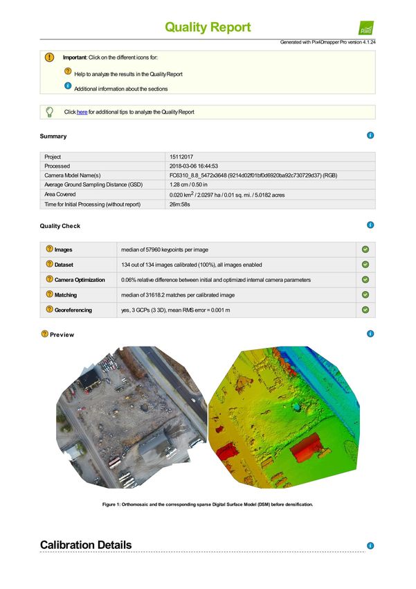
20 10 Test flights For our test flights, we used a DJI Phantom 4 pro drone which is equipped with a 20- megapixel one-inch sensor. This is a micro-drone class quadcopter that weighs under 2 kg. We taught this drone will give us the minimum quality of what we need to achieve, therefore we tested it first, the drone also had all the requirements for our purpose and was already used by our taskmaster. Requirements that we needed was a drone with a GNSS receiver, so we could run it on autopilot, also a camera mounted on a gimbal, and a battery time that would last the whole mission. The only negative side about this drone is that it is recommended to fly only temperatures over 0 Celsius. 10.1 Preparations Before our test we calculated with the help of pix4ds GSD (ground sampling distance) tool the possible GSD with the specifications of the camera mounted on the DJI Phantom 4 pro. As we can see in Figure 20 we would reach a theoretical GSD about 2 cm when flying at 50meters. Figure 20. GSD calculator
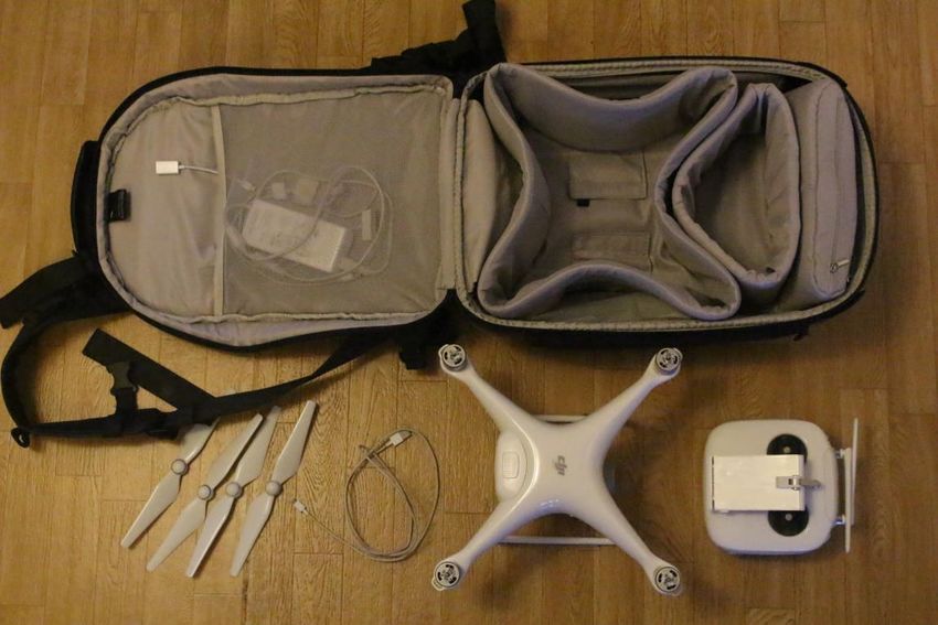
21
For route planning we tested both pix4Dcapture and DroneDeploy, they both work likewise
with simple interface and few choices for planning. These two route planning apps are easily
maneuvered on a smart phone, meaning no laptop is needed nor an internet connection.

On our smartphone, we planned the route we were going to fly. Figure 21 shows
Pix4dCaputures interface when planning the route. The settings that Pix4dCapture offered
us to change, were as seen to the right in Figure 21. Speed, overlap and camera angle. And
to the left the flying altitude. When we had our area stretched over the map it gave us an
estimated flying time and area size.

Figure 21. Pix4D user interface

When the area was covered on the app, and settings were made as we wanted them, we went
out to the actual area and got our drone ready for flight. Getting the DJI Phantom 4 pro ready
for flight was not more than a few easy steps. From getting the pieces out of the carrying bag
to flight-ready did not take more than a few minutes. Afterwards the drone returned, and the
data was collected either manually, by ejecting the mini SD-card and transfer the pictures in
to a computer, or then the pictures could be downloaded straight to the device that operated
the drone. And in picture 22 we see the drone-bag with content which made the whole
transportation aspect very convenient because of everything needed fitted in a small carrying
bag.
22

Figure 22. Drone-bag and content

The steps were following, connect your phone to remote controller, fasten propellers to the
drone, adding battery to the drone, unsecure the camera from its hold and then turn on the
devices. Before letting the drone out on its mission, we placed out GCPs that were a size of
40x40 cm around the area of flight. Then we measured the coordinates with a Topcon Hiper
Pro GNSS instrument for later geo-referencing, as seen in Figure 23 and 24 the coordinates
were measured for 60 epochs each.

Figure 24. Measuring GCP      Figure 23. GCP from above
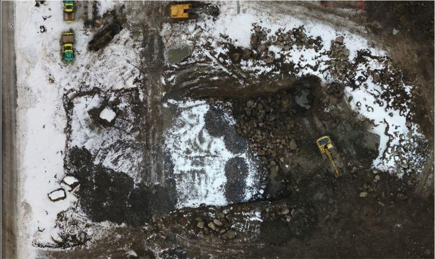
23
10.2 Test areas

We chose two areas for testing, the first one was Skeppsparken, approximately 2 ha (Figure
26). This because it could be taught of a prospering and surveying stage. Later, we found
our second area which was a pre-construction site approx. 0.65 ha (Figure 25). With the pre-
construction site, the goal was to fly over it several times and do a surveillance of the area.
Then compare the point-clouds when the area had changed during the excavations and
building steps.

Tulostettu Maanmittauslaitoksen asiointipalvelusta

Figure 26. Skeppsparken

 Tulostettu Maanmittauslaitoksen asiointipalvelusta

Figure 25. Pre construction site
24
10.3 Weekly flights

For our continuous follow up we chose only to continue with the pre-construction site as the
surface was changing from week to week and Skeppsparken was not going to change at all.
The pre-construction site was also better for us as the area was not as big as Skeppsparken,
resulting in faster processing.

Because we were going to fly over the same area multiple times we chose to build permanent
points for our GCPs, as seen in Figure 27 and 28. Now we just needed to measure the
coordinates on the points once and use the same points for every flight. Our points were nails
nailed to the asphalt with a flag fastened on the nail, this way we would more easily find
them next time. For the next flight we just needed to place out our GCP plates on the points
and then take the photos.

Figure 27. Building permanent GCP              Figure 28. Removing ice for GCP

10.4 Weather conditions

During this time, there were two test flights conducted over the pre-construction site. We
wanted to make flights every week but several factors made it impossible. Firstly, the months
from November to January are the darkest months in Finland, meaning we had a little gap
every day for about 3-4 hours to make these flights. Also, we had to take in mind that our
drone was not recommended to use in temperatures below 0 degrees Celsius, wind speeds
over 10 m/s or when it snowed or rained. This resulted in very few opportunities to conduct
flights.
25
The first flight started 15.11.2017 12:30 at +1 degree Celsius and wind speed around 3 m/s.
The sun had peaked and did not generate a strong lightning. The results were good because
due to the smooth lightning not creating sharp and strong shadows.

The second flight was done 26.01.2018 12:45 at +1,2 degrees Celsius and wind speeds below
4 m/s. The sky was a bit cloudy and the sun on its way down. The pictures were a bit dark
but very sharp with no interference from shadows.

11 Software for data
When the data was collected it was time to test the different software used for
photogrammetric calculations. Comparisons have been done before by students in the
Technical University of Denmark (2016) here they compared sensors and software. In their
conclusion of software, Agisoft Photoscan came out as a winner along with a MicMac.
Further reading also reveals that pix4D would be comparable depending on the subject of
interest.

We chose the try out four different software for our test. Agisoft Photoscan for their well-
known reputation, Pix4D because of their all in one solution (app for flying, cloud and
stationary options for processing), and Dronedeploy was also put to test as it seemed to be a
simple but functional software to meet most demands. Autodesk´s products for
photogrammetry was also tested as our client used these programs for other modelling.

11.1 Agisoft Photoscan

Agisoft Photoscan is a photogrammetric stand-alone software founded in 2006. This
software performs only processing of data and no app for route planning nor flying. Their
values and goals are providing a low-budget method for research and documentation. In their
website they are saying that “Throughout various case studies Photoscan proves to produce
quality and accurate results” (Agisoft Photoscan, 2018).

Agisoft offers a 30-day trial in demo mode that will give you the ability to test the program
but not be able to save or export anything. The first impression of the software was that it
was kind of complicated and support was only given from forums that were not that active.
But the more we used it, the software became easier and easier to understand and handle.
The results that Agisoft gave, was as their website claimed, “produce quality and accurate
results”. Agisoft also produces a full report of the processing that lets the user know what
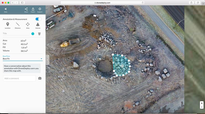
26
could have gone wrong if the results were bad or something was wrong. If processed properly
and no significant mistakes were made, the report would just give the user more confidence
in the results.

The software offered all kind of outputs like orthophoto, dsm/dtm and dense cloud for
example. With this followed also tools in the same software for editing, measuring and
classifications. Meaning Agisoft could measure and analyze the data itself or give an output
to another program and analyze it there. For an example; Agisoft exports a laz file that is
compatible with Autodesk and there the user would be able to model, analyze and further on
what Autodesk is capable of.

However, our conclusion was that it is a good program after a bit of practice. But the lack of
an app for the flying meaning that another software would be needed was not in our favor.
Instead of a cloud-based processing alternative Agisoft Photoscan offered a substitute that
were to set up a network cluster were several computers could process the data over the same
connected network that could be an alternative if processing data becomes large and fast
results is needed. But in general, a very good photogrammetric solution.

11.2 Pix 4D

Pix 4D is a rather new software, founded in 2011, but already a very popular software. Pix
4D offers an application for route-planning, a desktop application for processing the data on
the computer or cloud processing service. When the processing phase is done you can edit,
calculate and measure in the desktop application.

Pix 4D offers a 15-day free trial, with this trial you get access to both the route-planning app
(Pix 4D capture) and the desktop application (Pix 4D mapper). The impression of Pix 4D
applications were better than Agisofts Photoscan, it is more user friendly and easier to
understand. Pix 4D capture is very simple and it does not take long to plan the route. Arriving
to the test are, plan the route and to setup the drone, took about 10 minutes.

Depending on the computers capacity and the quality you want to achieve, you can choose
between low, medium or high quality. The lowest quality has the fastest processing speed,
but the quality is the poorest, with quality set on high, the processing speed is the slowest,
but the outcome is much better.

Pix 4D has a very good support forum, explaining basically everything about the program.
When the processing is done you get a very good quality report, on all the different results
27
there is a link to their website explaining what exactly that is. For example, if you do not
know how the program calculates the GCP accuracy, you simply click on a INFO button in
the quality report and it directs you their support forum where it is explained. They also have
a lot of good demonstration videos on their website and Youtube.

To sum up, Pix 4D is a very suitable software for us, with the route-planning app and the
autopilot function it is easy to get the footage we want, and with the same software to process
the data we do not need to buy or hire two different licenses.

11.3 Autodesk

Autodesk is a well-known maker of software that offers all sorts of products for 3D design,
engineering and software entertainment. For photogrammetry needs, Autodesk offers a
software named Recap that through cloud computing, computes the user’s images or laser
scanned data for stitching and modelling. If more editing features is needed, measuring
calculating for an example. The user simply opens the computed point cloud from Recap in
to another Autodesk software for further editing.

With the help of our client we were able to try what could be done with recap. We sent our
data collected with the drone and then they used it as input to Recap. With Recap the user
simply loaded the images to the cloud and then oriented them with GCP data. After that the
outputs were selected, Recap offers five different outputs, FBX, OBJ, RCM, RCS and
GeoTIFF. When these few steps were done the cloud stitched and calculated the images then
an email was sent to the user that the calculated data was ready and could be downloaded
through the A360 drive.

When playing around a bit with Autodesk our conclusion was that the possibilities were
almost unlimited with the help of all other software’s that Autodesk offered. But however,
we were not so convinced with the photogrammetric software itself, Recap. The lack of
control in processing, minimal report of the result and calculating methods made us wonder
how trustworthy the software´s output really was. The scan report (see Appendice 3) did not
contain crucial info as amount of points in point cloud, if the user wanted to know how many
points there were, he either had to have a software to tell him or dig in the output user log
text file.
You can also read