PROCEDURES FOR AGGREGATE INSPECTION - 2019 Construction Field Services Division Aggregate Quality Unit - State of ...
←
→
Page content transcription
If your browser does not render page correctly, please read the page content below
PROCEDURES FOR
AGGREGATE INSPECTION

                2019
 Construction Field Services Division
       Aggregate Quality Unit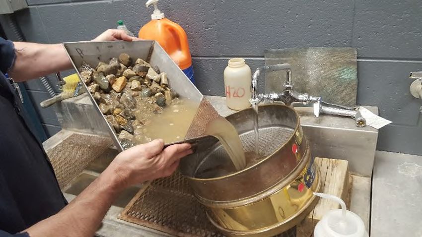
Engineering Manual Preamble

    This manual provides guidance to administrative, engineering, and technical staff.
Engineering practice requires that professionals use a combination of technical skills and
judgment in decision making. Engineering judgment is necessary to allow decisions to
account for unique site-specific conditions and considerations to provide high quality
products, within budget, and to protect the public health, safety, and welfare. This
manual provides the general operational guidelines; however, it is understood that
adaptation, adjustments, and deviations are sometimes necessary. Innovation is a key
foundational element to advance the state of engineering practice and develop more
effective and efficient engineering solutions and materials. As such, it is essential that
our engineering manuals provide a vehicle to promote, pilot, or implement technologies
or practices that provide efficiencies and quality products, while maintaining the safety,
health, and welfare of the public. It is expected when making significant or impactful
deviations from the technical information from these guidance materials, that reasonable
consultations with experts, technical committees, and/or policy setting bodies occur prior
to actions within the timeframes allowed. It is also expected that these consultations will
eliminate any potential conflicts of interest, perceived or otherwise. MDOT Leadership
is committed to a culture of innovation to optimize engineering solutions.

   The National Society of Professional Engineers Code of Ethics for Engineering is
founded on six fundamental canons. Those canons are provided below.

   Engineers, in the fulfillment of their professional duties, shall:
   1. Hold paramount the safety, health, and welfare of the public.

   2. Perform Services only in areas of their competence.

   3. Issue public statement only in an objective and truthful manner.

   4. Act for each employer or client as faithful agents or trustees.

   5. Avoid deceptive acts.

Conduct themselves honorably, reasonably, ethically and lawfully so as to enhance the
honor, reputation, and usefulness of the profession.

                                                i
Table of Contents
CHAPTER 1 – INTRODUCTION ................................................................................. 1
INTRODUCTION ...................................................................................................... 1
DEFINITIONS ........................................................................................................... 2
HEALTH AND SAFETY ............................................................................................ 5
CHAPTER 2 – SAMPLING PROCEDURES AND EQUIPMENT................................. 7
SAMPLING FREQUENCY ........................................................................................ 7
FIELD SAMPLE SIZE ............................................................................................... 8
SAMPLING FREQUENCY FOR SPECIALTY TESTING AT CONSTRUCTION FIELD
SERVICES (CFS) LABORATORIES ....................................................................... 9
SAMPLING TOOLS ................................................................................................ 10
SAMPLING ............................................................................................................. 12
OTHER SOURCES OF CONTAMINATION ........................................................... 16
RADIAL STACKER BUILT STOCKPILES .............................................................. 19
TRUCK, FRONT END LOADER, AND DUMPSTER BUILT STOCKPILES ............ 21
ON GRADE SAMPLING ......................................................................................... 24
TRUCKS AND RAILROAD CARS .......................................................................... 26
CHAPTER 3 - MDOT AGGREGATE SUPPLIER PROGRAM.................................. 27
INTRODUCTION .................................................................................................... 27
DEFINITIONS ......................................................................................................... 27
ALL MDOT AGGREGATE SUPPLIERS ................................................................. 28
NON-PREQUALIFIED AGGREGATE SUPPLIERS................................................ 29
PREQUALIFIED AGGREGATE SUPPLIERS ......................................................... 30
LABORATORY INSPECTIONS (PREQUALIFIED SUPPLIERS) ........................... 34
WAIVER PROCESS (ALL MDOT AGGREGATE SUPPLIERS) ............................. 36
DISTRIBUTION AND CONTACT INFORMATION.................................................. 36
CHAPTER 4 – LABORATORY SAMPLE SIZES AND SAMPLE REDUCTION ....... 39
LABORATORY SAMPLE SIZE ............................................................................... 39
MECHANICAL DEVICES ....................................................................................... 40
QUARTERING ........................................................................................................ 42
MINIATURE (MINI) STOCKPILE SAMPLING......................................................... 45
DRYING THE SAMPLE TO CONSTANT WEIGHT ................................................ 46
CHAPTER 5 – THE MECHANICAL ANALYSIS ....................................................... 49
ROUNDING PROCEDURES .................................................................................. 49
EXAMPLE PRODUCTION PROBLEM ................................................................... 49
COARSE AGGREGATE ......................................................................................... 50
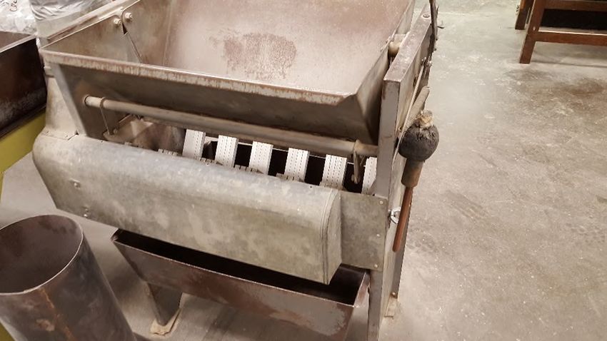
LOSS BY WASHING .............................................................................................. 51
MECHANICAL WASHERS ..................................................................................... 54
SIEVING ................................................................................................................. 55
DELETERIOUS PICKS ........................................................................................... 58
DENSE-GRADED AGGREGATES ......................................................................... 59
ii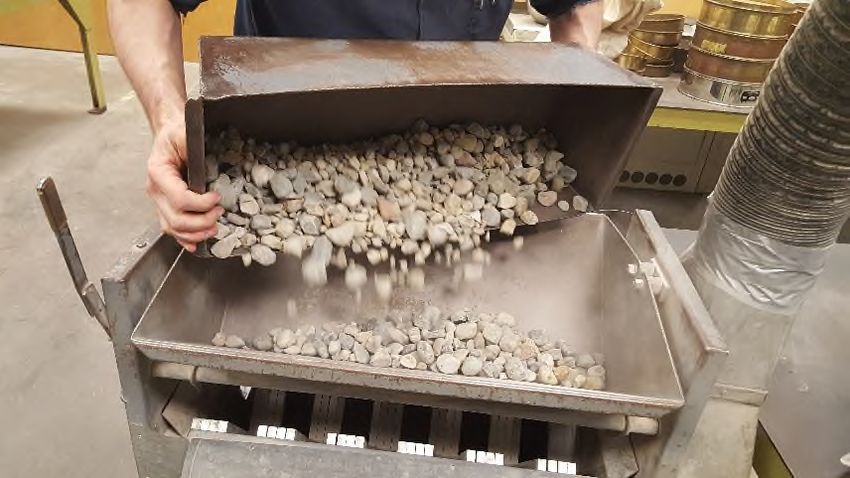
FINE AGGREGATE ................................................................................................ 59
 ORGANIC PLATE NUMBER .................................................................................. 60
 RUBBLE CHECK FOR CRUSHED CONCRETE AGGREGATE ............................ 60
 THE AGGREGATE INSPECTION DAILY REPORT ............................................... 61
 HOT MIX ASPHALT ............................................................................................... 62
CHAPTER 6 – PICKING CRUSHED AND DELETERIOUS MATERIAL................... 65
 CRUSHED PARTICLES ......................................................................................... 65
 DELETERIOUS AND OBJECTIONABLE PARTICLES .......................................... 65
 DELETERIOUS PARTICLES.................................................................................. 66
CHAPTER 7 – OTHER TESTING PROCEDURES ................................................... 69
 ORGANIC IMPURITIES TEST (THE COLORIMETRIC TEST) .............................. 69
 ANGULARITY INDEX TEST (MTM 118) ................................................................ 70
 UNCOMPACTED VOID CONTENT OF FINE AGGRGATE ................................... 73
 AGGREGATE WEAR INDEX TESTING (MTM 111 AND MTM 112) ...................... 74
 FREEZE-THAW TESTING ..................................................................................... 77
 BULK DRY SPECIFIC GRAVITY............................................................................ 80
 SHRP TEST............................................................................................................ 81
 FLAT PARTICLES, ELONGATED PARTICLES, OR FLAT AND ELONGATED
 PARTICLES ............................................................................................................ 82
 SAND EQUIVALENT TEST .................................................................................... 82
 RESISTANCE TO DEGRADATION OF SMALL-SIZE COARSE AGGREGATE BY
 ABRASION AND IMPACT IN THE LOS ANGELES MACHINE .............................. 83
 MOISTURE CONTENT .......................................................................................... 85
REFERENCES .......................................................................................................... 87

                                                        iii
INDEX OF FIGURES
FIGURE 1: ORDER OF PRECEDENCE FOR PROJECTS ............................................................. 8
FIGURE 2: CANVAS BAGS, PLASTIC OR STEEL PAILS CAPABLE OF HOLDING APPROXIMATELY
    SIXTY POUNDS .......................................................................................................... 10
FIGURE 3: SQUARE POINT SHOVELS (ROUND POINT SHOVELS ARE NOT ALLOWED) ............... 10
FIGURE 4: SQUARE NOSED SCOOPS ................................................................................. 11
FIGURE 5: A SAMPLE THIEF MADE FROM 1½ TO 2 INCH DIAMETER BY APPROXIMATELY 30 INCHES
    LONG THIN WALL ELECTRICAL CONDUIT TO SAMPLE FINE AGGREGATES (SAND) ONLY ....... 11
FIGURE 6: 5 FOOT T-HANDLE BUCKET AUGER MADE FROM THICK WALLED GALVANIZED IRON PIPE
    WITH BLADES WELDED ON EITHER A 3 OR 4 INCH OUTSIDE DIAMETER FOOT LONG THIN
    WALLED PIPE ............................................................................................................ 11
FIGURE 7: SHOVEL TAKING SAMPLE .................................................................................. 12
FIGURE 8: TOP VIEW SAMPLE PATTERN “MINI” STOCKPILE AFTER BACK BLADING ................. 12
FIGURE 9: TOP VIEW BACK BLADING SAMPLING METHOD ................................................... 13
FIGURE 10: THIEF TAKING SAMPLE ................................................................................... 13
FIGURE 11: CONVEYOR CROSS SECTION .......................................................................... 14
FIGURE 12: CONVEYOR DUMPING ON GROUND WITHOUT BAFFLE ........................................ 14
FIGURE 13: CONVEYOR WITH BAFFLE ................................................................................ 15
FIGURE 14: “CONTAMINATED” CORE OF ANY STACKER BUILT STOCKPILE ............................ 15
FIGURE 15: CONVEYOR WITH TEMPLATES .......................................................................... 16
FIGURE 16: MECHANICAL SAMPLING DEVICE...................................................................... 17
FIGURE 17: CONVEYOR DUMPING INTO LOADER ................................................................. 17
FIGURE 18: SAMPLING DEVICE ......................................................................................... 18
FIGURE 19: CONE STOCKPILE PROPORTION ...................................................................... 18
FIGURE 20: TOP VIEW OF CONE STOCKPILE ...................................................................... 19
FIGURE 21: LOADING FROM CONE SHAPED STOCKPILE....................................................... 19
FIGURE 22: LOADER REMOVING MATERIAL FROM END OF STOCKPILE .................................. 20
FIGURE 23: RADIAL STACKER STOCKPILE PROPORTIONS .................................................... 20
FIGURE 24: TYPICAL SAMPLE PATTERNS – LEFT SHOW DISTRIBUTION OF SAMPLING SITES
    THROUGH THE STOCKPILE IF TEN SAMPLE POINTS ARE TAKEN FROM A RADIAL STACKER
    STOCKPILE- RIGHT SHOWS DISTRIBUTION OF SAMPLING SITES THROUGH THE STOCKPILE IF
    SIX SAMPLE POINTS ARE TAKEN. ................................................................................. 20
FIGURE 25: FRONT END LOADER BACKING AWAY............................................................... 21
FIGURE 26: TRUCK BUILT STOCKPILE ................................................................................ 22
FIGURE 27: TRUCK DUMP, FRONT END LOADER, OR DUMPSTER STOCKPILE ........................ 22
FIGURE 28: DIAGONAL SAMPLE PATTERN - TOP VIEW ........................................................ 23
FIGURE 29: AGGREGATE DUMPED OVER W ALL .................................................................. 23
FIGURE 30: TOP VIEW OF PAN DUMP STOCKPILE ............................................................... 24
FIGURE 31: ON GRADE SAMPLE POINTS ............................................................................ 25
FIGURE 32: MDOT AGGREGATE SUPPLIER SAMPLING FREQUENCIES .................................. 29
FIGURE 33: AASHTO AND ASTM MINIMUM LABORATORY TEST SAMPLE SIZES ................... 39
FIGURE 34: MDOT MINIMUM LABORATORY TEST SAMPLE SIZES......................................... 39
FIGURE 35: SAMPLE SPLITTER .......................................................................................... 40
FIGURE 36: VIEW INSIDE SPLITTER ................................................................................... 41
FIGURE 37: SPLITTER FILLED – TOP VIEW ......................................................................... 41
FIGURE 38: DUMPING MATERIAL INTO SPLITTER ................................................................ 42

                                                             iv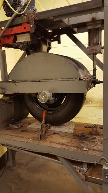
FIGURE 39: POUR RINSE WATER INTO STACKED SIEVES .................................................... 52
FIGURES 40: RINSE MATERIAL TO SIDE OF THE SIEVE AND BACK INTO THE PAN ...................... 53
FIGURE 41: MECHANICAL WASHER ................................................................................... 54
FIGURE 42: SIEVE NEST ................................................................................................... 55
FIGURE 43: MAXIMUM ALLOWABLE W EIGHT RETAINED FOR SELECTED SIEVES WITHOUT
    OVERLOADING .......................................................................................................... 55
FIGURE 44: SIEVE IN BOWL FOR 1 MIN OF HAND SHAKING .................................................... 56
FIGURE 45: MARBLE STACKED SHOWING POOR INTERLOCKING ............................................ 70
FIGURE 46: IRREGULAR SHAPES SHOWING GOOD INTERLOCKING ......................................... 70
FIGURE 47: ANGULARITY INDEX TESTING FUNNEL .............................................................. 71
FIGURE 48: ANGULARITY INDEX TESTING COMPUTATION TABLE .......................................... 72
FIGURE 49: UNCOMPACTED VOIDS TEST APPARATUS ......................................................... 73
FIGURE 50: ASTM AND AASHTO OPTIONS FOR THE UNCOMPACTED VOID TEST................. 74
FIGURE 51: W EAR TRACK W ITH SPECIMEN IN PLACE ......................................................... 75
FIGURE 52: STATIC FRICTION TESTER ............................................................................... 76
FIGURE 53: PETROGRAPHIC EXAMINATION......................................................................... 76
FIGURE 54: GUIDELINES FOR APPROVAL OF SOURCES BASED OFF FREEZE-THAW TEST RESULTS
    ............................................................................................................................... 79
FIGURE 55: PROPORTIONAL CALIPER DEVICE .................................................................... 82
FIGURE 56: SAND EQUIVALENT TEST ................................................................................ 83
FIGURE 57: LA ABRASION GRADATION B- AGGREGATE SIEVE SIZES ................................... 84
FIGURE 58: LOS ANGELES MACHINE ................................................................................. 85

                                                                  v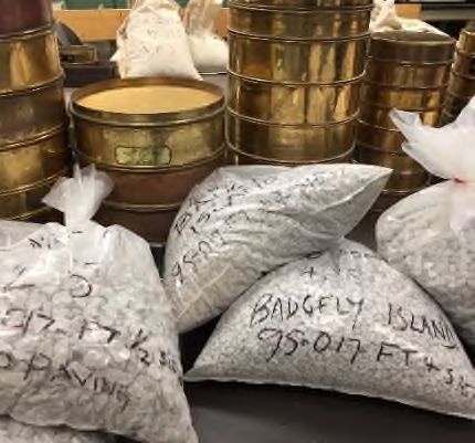
CHAPTER 1 – INTRODUCTION
INTRODUCTION
This manual is designed to provide guidance for the sampling, testing, and reporting of test results
for aggregate materials as standardized by the Michigan Department of Transportation (MDOT).
Many, but not all, situations the technician encounters will be covered. Adherence to the
procedures contained herein will ensure that tests performed by numerous individuals on the
same lot of aggregate materials will be in substantial agreement.
The technician conducting the inspection can be a Department employee or a consultant under
contract to the Department and is the authorized representative of MDOT. It is the duty of all
technicians to acquaint themselves in full with the specifications and instructions applying to their
work. A thorough familiarity with the appropriate tests conducted on properly selected samples
is essential for satisfactory performance of the technician’s duties. All technicians performing
aggregate testing for state or federally funded projects require Michigan Certified Aggregate
Technician (MCAT) training at the level appropriate for the acceptance work. A few examples and
the MCAT level required are listed below:
Granular fill (Level 1)
Sub-base (Level 1)
Base (Level 1)
Concrete aggregates (Level 2)
Chip Seal aggregates (Level 2)
Bituminous aggregates (Level 2)
Sampling (Sampling Only)
The American Association of State Highway and Transportation Officials (AASHTO), the
American Society for Testing and Materials (ASTM) and MDOT (Michigan Test Methods- MTMs)
publish many construction standards. The Federal, state, local governmental agencies, and
individual companies may develop their own standards. Agencies may adopt published
standards, or parts of published standards, and rename them as a test method. Michigan Test
Methods can either be stand alone, or can include modifications to other test methods. Therefore,
it is important to know which testing standards are being used.
Conformance to requirements can be determined by quality control testing. If something being
measured does not meet, then you have nonconformance.
Many of the federal and state agencies have adopted Quality Control, Quality Assurance, Total
Quality Management and ISO-9000:2000 (International Organization for Standardization)
programs. To be successful these programs need much more than adoption and verbal
1
commitment by management. It takes an active leadership and participation in the quality
process by all members of the organization. A commitment to training is also a major component
of these programs. MDOT laboratories and Industry Laboratories performing Quality Control or
Quality Assurance Testing are required to meet certain training and material tracking
requirements.

Product quality control is a direct reflection of the organization’s leadership and attitude. This
attitude also affects the external image of the organization as perceived by many individuals.
Quality control is more than a product shipped or service provided. Quality control techniques can
be applied to customer relations, product production, laboratory procedures and documentation,
to name a few.

One of the biggest challenges any technician may face is communication. The technician must
know and understand how to use the applicable quality control standards. Individuals might
interpret the written procedures differently when it comes to performing a specific procedure.
Arguments develop about a standard’s correct interpretation and whether a procedure is being
carried out correctly.

Every business must establish clear communications, from the president or owner, down to the
newest employee and right back up to the president or owner. Information must flow smoothly
between parties, in a form acceptable and understandable to everyone.

In business, the buyer and seller also should establish mutual confidence through a relationship
based on clear communication.

It is recommended before production starts for a source or project, schedule a meeting to discuss
expectations, such as sample taking or the running of the test. Work through the first procedure
together, making sure you reach agreement on how procedures will be done. Don’t lock yourself
into thinking the old ways are the best ways. As technology changes, procedures change. Let
your views reflect technology’s positive progress.

DEFINITIONS

An aggregate is a produced product having specific physical and gradational properties and is
created by manipulation of material through a processing operation. The material may be from
natural sand and/or gravel deposits, quarried bedrock, slag from steel mills or copper refineries,
debris from mining operations, or crushed Portland cement concrete.

Acceptance Tests – Tests conducted on produced material for acceptance or rejection. These
tests may be conducted any time including incorporation into the finished work. These tests
include MDOT’s quality assurance testing.

Aggregates (Crushed Stone) – These aggregates are derived from the crushing of quarried
bedrock.

Aggregates (Natural Gravel) – These aggregates occur in natural, unconsolidated deposits of
granular material which are derived from rock fragments such as boulders, cobbles, pebbles and
granules and may be rounded, crushed or a combination of both. These deposits may be found
either above or below the water table. Natural gravel aggregates consist predominantly of
particles larger than the No. 4 sieve (4.75 mm).

                                                2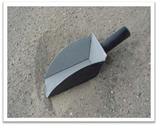
*Natural Gravel Aggregates and Crushed Stone Aggregates are both included in the
Standard Specifications for Construction under the definition of Natural Aggregates.

Aggregate Source Inventory Number – Any source that provides aggregate materials for MDOT
projects must have an ASI number, which the department uses to track the material from creation
to incorporation. The first two digits of the number correspond to the county number and the last
three are a numerical designation that is sequential. Every different type of material that is
produced at a physical location will have its own designation, as acceptance testing is tied to the
source number. ASI numbers are assigned from the Aggregate Quality Unit. You may apply for
a source number by contacting your Region Materials contact or directly contacting Aggregate
Quality.

Coarse Aggregates – Those aggregates having particle sizes basically finer than 3 inches (75
mm) in diameter and containing negligible amounts of material finer than the No. 4 sieve (4.75
mm). The highest quality aggregates are used in Portland Cement Concrete and Hot Mix Asphalt
(HMA) pavements.

Crushed Portland Cement Concrete Aggregates – Those aggregates obtained by crushing
salvaged Portland Cement Concrete (PCC). Coarse, dense-graded and open-graded aggregates
manufactured from salvaged PCC must conform to the grading and physical requirements of the
most current Standard Specifications for Construction (SSfC).

There are several standard and special provisions relating to the use of crushed concrete for
specific purposes. For Instance, Dense Graded Aggregate for Base course made from PCCC
(Portland Cement Crushed Concrete) must not contain more than 5.0% rubble or HMA by particle
count (Standard Specifications for Construction 902). Always make sure when testing material
for acceptance that you have the most current and complete specifications for the material and
its use.

Dense-Graded Aggregates – Those aggregates composed of rock fragments finer than 1½ inches
(37.5 mm) in diameter and are uniformly graded to finer than the No. 200 sieve (0.075 mm).
When properly produced, these aggregates can achieve high density and stability. They are
generally used for base courses and shoulders.

Distribution Hub – A location that stores aggregate material for distribution that is not the source.
Acceptance tests run on materials before being stored in a distribution hub are no longer valid
once being placed in a distribution hub. When acceptance testing is run on material that is placed
in a distribution hub, the ASI# used on the test results will correspond to the location that the
material originated. Extreme care, organization and internal material tracking must be used by
companies that utilize distribution hubs.

Fine Aggregates – Those aggregates composed of rock fragments finer than the No. 4 sieve (4.75
mm) and coarser than the No. 200 sieve (0.075 mm). Generally, these are blended with coarse
aggregates to produce Portland cement or HMA mixtures.

Independent Assurance Tests – Tests conducted to evaluate both the technician’s sampling and
testing procedures and the condition of the testing equipment. The initial sample is split into two
halves. One half is tested by the technician and the other half is tested by the independent
assurance inspector. The independent assurance inspector cannot be involved in the
project and must use different equipment to test the aggregate. The Independent Assurance

                                                 3
Test will be completed and compared to the results of the Acceptance Test. These samples may
be submitted to the Construction Field Services Aggregate Lab for processing if necessary.
Information Tests – These tests are for information only and not intended for acceptance or
rejection of aggregate materials. If a technician feels that an aggregate material has changed
substantially from when it was accepted, or suspects an aggregate’s quality, the technician may
perform an Information Test. Based on the test results, two courses of action are available: 1) If
the material is out of specification requirements, the technician may require additional Acceptance
Tests; or 2) If the material is substantially within specification requirements, no further action is
required. However, these passing results do not change the sampling frequency.
Intermediate Aggregate – These aggregates are passing the ½ inch sieve and retained on the
No. 4 sieve. This aggregate category is used in production of aggregate blends for Optimized
Gradation.
Natural Sand – An accumulation of unconsolidated rock fragments or detrital particles derived
from the chemical and/or physical disintegration of rocks as part of the natural weathering process
which is uniformly graded and consists predominantly of particles smaller than the No. 4 sieve
(4.75 mm).
O.G.D.C. - Open-Graded Drainage Course Aggregate – These aggregates consist of coarse
gradations, including pea gravel, with minor amounts of material finer than the No. 200 sieve
(0.075 mm). They may be gravel, stone, crushed concrete or slag. They are used as drainable
base material immediately below Portland Cement Concrete and HMA pavements.
On-Site and Pre-Existing Material – Some jobs/projects call for re-use of material that had been
incorporated into the work in a previous job at the same location, as well as call for use of material
at the physical location. Prior job acceptance of material does not waive the ability or need for
current acceptance testing. Much can happen to the material in the intervening time, including
but not limited to, compaction, degradation and leeching of fines.
Quality Control Tests – These are tests run by a material supplier for his own information and
used to control the quality of material being produced, includes testing contracted by the supplier
to a qualified testing lab. The frequency of testing is dependent upon the uniformity of the
production operation and is stated in the supplier’s quality control plan. Each quality control plan
is reviewed and approved by both the controlling MDOT Region and Construction Field Services
Aggregate Quality.
Slag Aggregates – Those aggregates produced as a co-product of the refining operations that
turn iron and copper ore into refined metals. This includes Steel Furnace Slag, Blast Furnace
Slag and Reverberatory Slag.
Stone Sand – A fine aggregate produced from quarried rock which is uniformly graded and
consists predominantly of particles smaller than the No. 4 sieve (4.75 mm).
Stamp Sand – A fine aggregate which is the end result of a stamp-mill crushing operation. This
aggregate is composed of hard, durable particles, uniformly graded in size and consists
predominantly of particles smaller than the No. 4 sieve (4.75 mm).
4HEALTH AND SAFETY
It is the technician’s responsibility to make sure their personal protective equipment meets current
Michigan and Federal Occupational Health and Safety Administration standards.
Prior to entering a construction zone, processing area, pit or quarry, make sure you have all the
necessary personal protective equipment. This equipment includes but is not limited to; steel-
toed work boots, reflective vest or clothing, hard hat, safety glasses, hearing and dust protection.
When entering a construction zone, processing area, pit or quarry, check in with the person in
charge of the operation. Do not enter an operation to take samples without informing someone
on-site. Observe traffic patterns and park your vehicle in a safe location. Ask for permission
before you climb onto equipment or venture around to observe the operation. Most quarries or pit
operations require specific safety training on a yearly basis for both employees and visitors that
must be completed prior to being allowed on-site.
People working with equipment day after day may become too accustomed to their work
environment. If their job has become a repetitive routine, they might not notice what’s going on
around them. Family problems, after-work plans or an inattentive attitude can contribute to a lack
of concentration and, potentially, cause an accident.
Accidents cost much more than money. In addition to increased insurance premiums, medical
bills, workman’s compensation, and, in the most tragic cases, death benefits, the company loses
time during the accident investigation, reputation in the local community, and morale among
employees. Also, it’s costly to educate new employees to take the place of their injured
counterparts.
In addition to safety, health issues are important to the employee. What you do today will affect
your “Quality of Life” in the future. Spending the rest of your life with a work related injury or illness
is not part of the “American Dream.”
Working around processing equipment and in laboratories with constant exposure to dust may
lead to long term lung related health issues. The Occupational Health and Safety Administration
has published exposure limits.
Experts generally agree that sound levels below 80 decibels (dB) are considered to be safe.
However, many pieces of equipment in the work environment exceed this sound level. Exposure
to a level of 85 dB over an 8 hour work day can cause permanent hearing loss. A typical leaf
blower generates enough dB’s to damage your hearing is less than one minute.
Repetitive activities or awkward postures can be cumulative over time and result in long term
musculoskeletal problems. As you age, your body’s ability to repair itself decreases. An example
of this could be the development of lower back or leg pain from repetitive lifting of heavy objects.
Field samples of aggregate can exceed 50 pounds in weight and may need to be transferred from
the ground to the bed of a truck, please plan accordingly.
Think about your actions and what you want your “Quality of Life” in the future to be before it is
too late.
5Everyone agrees that health and safety is an important part of the work environment.
In addition, health and safety standards change. Be sure you’re aware of the current government
health and safety regulations and company safety policies on your job.
6CHAPTER 2 – SAMPLING PROCEDURES AND
EQUIPMENT
SAMPLING FREQUENCY
To properly sample materials, you must have a clear understanding of how materials are
stockpiled, blended or placed. This will help you obtain representative samples of the material
being tested.
In general, the Michigan Department of Transportation’s definitions for quality control and quality
assurance for aggregates are: Quality Control is all the processes used by the contractor or
supplier to ensure specification material is provided to the project: Quality Assurance is the
procedures and tests conducted by the Department to verify and accept for payment purposes
that the material meets specifications.
Sampling for acceptance by MDOT can be done anywhere from the production site (quarry site,
sand & gravel source, etc.) to incorporation in the finished product. The justification for this is
found in the Michigan Department of Transportation Standard Specifications for Construction
under Division 1, General Provisions, Section 105.05 Approval of Materials Incorporated into the
Work.
The minimum acceptance testing sampling frequency for suppliers or sources is listed in the next
chapter, the MDOT Aggregate Supplier Program. In addition, special provisions may be added
to contracts which change the location or sample frequency. The basic sampling frequencies are
presented in the following Chapter.
Closely examine the contract proposal for special provisions or supplemental specifications.
Special provisions generally deal with how to do something or alter material specifications on a
project specific basis. However, frequently used special provisions become part of the contract
documents when a specific set of criteria is met. Supplemental specifications are added to every
project and usually replace or alter material specifications, procedures or introduce new materials.
Figure 1 shows the order of precedence for MDOT projects, with the top listing taking precedence
over those below.
7Unique Special Provisions- Project Specific Documents
Special Provisions
Supplemental Specifications
Project Plans & Drawings (Plan Dimensions> Calculated
Dimensions> Scale Dimensions)
Standard Plans
Standard Specifications
Figure 1: Order of Precedence for Projects
No matter how much planning is put into acquiring a sample, it all becomes worthless if
the sample does not truly represent the total material. Discard any non-representative
samples.
FIELD SAMPLE SIZE
MTM 107 Michigan Test Method for Sampling Aggregates lists minimum aggregate field
sample sizes as below.
Fine aggregates and Granular Material Class IIIA for independent assurance or acceptance
test - approximately 25 lbs. (11 kg) which equates to roughly one half of a standard canvas sample
bag.
Coarse, Dense-Graded, Open-Graded aggregates and Granular Materials (except Class IIIA)
for independent assurance or acceptance test - approximately 50 lbs. (25 kg) which equates to
one full standard canvas sample bag.
Aggregates for L.A. Abrasion test and Micro-Deval (as produced) - approximately 120 lbs. (50
kg) which equates to two full standard canvas sample bags.
Aggregates for Concrete Mix Design - approximately 60 lbs. (25 kg) which equates to one full
standard canvas sample bag.
*For both abrasion and mix design - approximately 120 lbs. (50 kg) which equates to two full
standard canvas sample bags.
ASTM and AASHTO standards have guidelines for the minimum field sample sizes for laboratory
testing based on the nominal maximum size of aggregates. When collecting a field sample for
MDOT the minimum field sizes listed above apply unless altered by special provision or
supplemental specification. Local government agencies and private contractors may have
8different requirements. Therefore, you can see the necessity of verifying proper field and test
sizes before collecting the sample.
SAMPLING FREQUENCY FOR SPECIALTY TESTING AT CONSTRUCTION FIELD
SERVICES (CFS) LABORATORIES
The following is the Michigan Department of Transportations (MDOT) frequency of sampling and
testing for source approval of aggregates for use on MDOT and federally funded projects:
Los Angeles (LA) Abrasion (AASHTO T 96 and Michigan Test Method 102) – Sources furnishing
dense-graded, open-graded, and coarse aggregates must have a minimum of one LA Abrasion
test conducted every five years. In addition,
Bituminous mixtures - if LA Abrasion is greater than 35 percent loss, testing must be
conducted annually,
Crushed concrete- LA Abrasion testing must be conducted annually.
Insoluble Residue (MTM 103) – Quarried limestone and dolomite sources furnishing aggregates
for dense graded aggregate and bituminous mixtures must have a minimum one insoluble residue
test conducted every five years, or whenever there is a change in the deposit.
Wear Track - Aggregate Wear Index (MTM 111) – Quarried, slag, and Igneous/metamorphic
sources furnishing aggregates for bituminous mixtures or top coarse concrete must have a
minimum one AWI wear track polishing test conducted approximate every five years. Additional
testing may be warranted if major changes in deposit occur.
Freeze-Thaw Durability (MTM 113, 114 and 115) – Sources furnishing coarse aggregate for
Portland cement concrete must have one freeze-thaw durability test conducted every five years.
Additional testing may be warranted if there are major changes in the deposit or production
method. If the current bulk dry specific gravity of the sample used to develop any concrete mixture
is more than 0.04 less than the bulk specific gravity of the most recent tested freeze-thaw sample
or another physical property change such as the deleterious content, the aggregate will be
considered to have changed characteristics and be required to have a new freeze-thaw test
conducted prior to use on department projects. The aggregate producer may also request
additional freeze-thaw testing if their current freeze-thaw test result on record is border-line
relative to potential high quality applications, but only if there is indication that the characteristics
have improved sufficient to warrant a new test. Specific Gravity testing of sources will be done
yearly in the intervening years to confirm results are in line with material tested for Freeze-thaw.
9SAMPLING TOOLS
Some common field sampling tools are:
Figure 2: Canvas Bags, Plastic or Steel
Pails capable of holding approximately
sixty pounds
Figure 3: Square Point Shovels (Round
Point Shovels are not allowed)
10Figure 4: Square Nosed Scoops Figure 5: A Sample Thief made from 1½ to 2 inch diameter by approximately 30 inches long thin wall electrical conduit to sample fine aggregates (sand) only Figure 6: 5 foot T-handle Bucket Auger made from thick walled galvanized iron pipe with blades welded on either a 3 or 4 inch outside diameter foot long thin walled pipe 11
SAMPLING

MTM 107 explains the approved sampling procedures in detail. The basic procedure will be
summarized in the following paragraphs of this manual. To obtain a sample increment of an
aggregate product using a scoop or square point shovel: (1) remove the surface area of the
material to be sampled; (2) dig down into the material approximately one foot or the thickness of
the material if has been placed on the grade. If geotextile separator is used be careful not to tear
or punch a hole in it.

                                 Figure 7: Shovel Taking Sample

As illustrated in Figure 7, insert the shovel or scoop at the base of the hole. Push the shovel into
the material and pull it upward to fill the shovel or scoop. Empty it into the sample container. This
represents one sample increment. Do this in as many different areas as necessary to obtain the
recommended representative field size sample.

Figure 8 illustrates a typical random sample pattern in a back-bladed “mini” stockpile. Observe
the flattened surface for signs of segregation. If the surface appears uniform, it is not necessary
to dig into the flattened surface to create a vertical face as shown in Figure 1 prior to obtaining
your sample increment.

             Figure 8: Top View Sample Pattern “Mini” Stockpile after Back Blading

The three areas back-bladed in Figure 9 are arranged from the fine to coarse sides of the
stockpile. The area selected should be approximately where the future shipping face will be
located. After the front end loader operator has pulled material down, distribute your samples
equally between the three locations. Figure 9 shows six randomly selected sample increment

                                                 12
sites. As with the “mini” stockpile, it is not necessary to dig into the flattened surface to create a
vertical face prior to obtaining your sample if there is no observable segregation.
Coarse Side
Fine Side
Figure 9: Top View Back Blading Sampling Method
A “sample thief” may be used only to sample fine aggregates (sand). First, remove the loose
surface material from the sampling area. Push the sample thief into the stockpile 12 to 18 inches.
Then, remove the tube and empty it into the sampling container, taking care to remove any
material stuck to the outside of the tube before emptying into your sample bag. Continue this
process randomly until you obtain the proper field sample size. A sample thief inserted into a
stockpile is illustrated in Figure 10.
Figure 10: Thief Taking Sample
Although seldom used, the bucket auger can be employed to obtain aggregate samples. This
method works best on stockpiles of material with low percent crushed or finer gradation. The size
of the auger opening will limit the maximum size of aggregate particle that can be sampled.
If the sample is to be obtained from truck, front end loader, or dumpster built stockpiles before
they have been bladed flat prior to adding the next layer, remove the dry surface material from
the area of the sample site, turn the auger until it reaches sufficient depth to obtain a sample
increment. Empty the auger into a sample container. Repeat the procedure in several locations
to obtain a representative field sample.
If the dumps have been prepared for the next layer, use the sample pattern for bottom dump earth
movers and there is no need to remove material before auguring into the surface of the stockpile.
With truck built stockpiles, the layers of material are two to four feet deep. Bottom dump earth-
13movers spread their loads over a much larger area. When sampling with the auger, take care not
to bore into previously sampled material.
SOURCES OF SEGREGATION
When moving materials to or from stockpiles, segregation of the aggregates can be a problem.
All aggregates are subject to segregation each and every time it is handled.
Conveyors carrying material to the stockpiles vibrate causing the fine material to separate and
settle to the bottom, as illustrated in Figure 11. Also, the distance between the rollers and the
length of the conveyor system affects aggregate separation or segregation.
Figure 11: Conveyor Cross Section
The degree of aggregate segregation depends on how the operator sets up the machinery. If a
pre-screening operation is planned where the oversized stone is diverted to a separate crusher,
extra care must be taken to blend the crushed oversize stone back with the fine material. Usually,
the operator deposits the sized, crushed stone back on top of the conveyor as it travels to the
stockpile. This can also happen with a single portable plant containing a vibrating screen and
crushers combined into one unit.
If segregated material continues to stockpiles, bins, trucks or bottom dump earthmovers without
any correction, segregation can become a major problem. The material’s gradation will not be
consistent. The stockpile may look similar to Figure 12 with the fine material falling towards the
conveyor and the coarse material falling away from the conveyor.
Figure 12: Conveyor Dumping on Ground without Baffle
Placing baffles and other mechanical devices in the ends of conveyors can help control
segregation problems. A typical mechanical device is illustrated in Figure 13.
14Figure 13: Conveyor with Baffle
Before taking the sample, view the operation to observe how the material is flowing into the
stockpile. Walk around the pile. Look for signs of segregation.
If the machinery has already left the pit or quarry area, walk around the stockpiled material. Look
for signs of segregation. Try to figure out how the material will be loaded for shipping.
If the stockpile has a small shipping face, one sample may be adequate. If the stockpile has a
shipping face larger than what will be loaded on one truck, it will be necessary to take several
samples and conduct sieve analyses to determine how much variation is present across the
shipping face. If the variation is greater than 5 percent on any sieve with an opening larger than
No. 200 sieve, the variation may cause problems. The variation in the No. 200 sieve will depend
on the maximum permissible amount passing.
WASH PLANT CONTAMINATION
Wash plants producing coarse aggregates (stone) may have a buildup of contaminated aggregate
in their stockpile’s center. The loader operator may not reach the center of the pile for several
days or weeks because new processed aggregate may have been added to the stockpile or,
perhaps, the plant may have been down for repairs or weather conditions.
Fine material, such as clay, silt and fine stone dust from the stone crushing process may not
completely wash off the aggregate as it flows through the wash operation. This fine material is
suspended in the water coating the larger aggregate particles. This excess water drips onto the
conveyor belt and then drips from the end of the stacking conveyor onto the stockpile. Over time
this small amount of the clay, silt and dust from the crushed stone builds up in the center of the
pile. When the loader operator reaches this point, this “contaminated” material will be loaded.
This is illustrated in Figure 14.
Figure 14: “Contaminated” Core of Any Stacker Built Stockpile
15The technician must be aware this problem may exist. Retesting the aggregate in the pile’s center
can ensure that the loss by wash and gradation meets specifications or if the pile’s center must
be washed again.
OTHER SOURCES OF CONTAMINATION
When using earth-movers or dump trucks for stockpiling aggregate, the equipment’s tires will
carry undesirable material from the pit or quarry floor up on the stockpile causing contamination,
especially after a rain or in the spring or fall when the ground is wet. In addition, heavy equipment
traveling on the stockpiles will compact the aggregate and cause breakdown.
Another source of contamination is the wind during summer dry periods. Dust cast into the air by
moving equipment will settle on the surface of the stockpile and increase the loss by wash.
When aggregate piles are manipulated while frozen, the finer particles can freeze to the larger
particles, rendering standard stockpile management practices unsatisfactory. They cannot be
mixed adequately and “breaking” into a pile by removing frozen outer material can significantly
change the gradation of material.
Contamination of crushed concrete is anything that is not crushed concrete, examples are brick,
shingles, HMA coated particles and household construction debris.
CONVEYOR BELT SAMPLING
Sampling from a conveyor belt can produce a very representative sample of aggregate if done
properly. Merely obtaining a sample at the beginning or end of production does not provide a
representative sample.
If you decide to take a sample from a conveyor, keep safety in mind. Closely observe the material
on the conveyor. How is it flowing to the stockpile? It is extremely important to inspect the belt
returning under the conveyor. Noting how much fine material sticks to the belt as it makes its
cycle around the conveyor.
It is recommended that a minimum of three approximately equal increments be sampled from the
stopped conveyor belt to obtain a representative sample. To do this, you will need two templates
formed to the conveyor curvature as illustrated in Figure 15.
Figure 15: Conveyor with Templates
Push the templates through the aggregates at the selected site. The distance between the
templates will depend upon the width of the conveyor belt and the size of the field sample needed.
16Use a scoop to remove the aggregate between the templates and place it in the sample container.
Use a brush to remove the small amount of aggregate between the templates that the scoop
missed. Take care not to remove aggregate sticking to the belt as the belt makes its cycle around
the conveyor. Some conveyors have a mechanical sampling device attached to their end, as
illustrated in Figure 16.
Figure 16: Mechanical Sampling Device
Push the pan mounted on a pair of sliding mechanisms all the way across the stream of flowing
aggregate and return it to the starting point. Through a door in the bottom of the pan, the material
empties into a pail or bag. It is recommended that this procedure be done a minimum of three
times to obtain a representative sample.
Another method of sampling from a radial stacking conveyor can be done by repositioning the
conveyor to discharge into a loader bucket, as shown in Figure 17. Move the loader away from
the stockpiling area to a safe working area. Dump the bucket on the ground. Obtain a sample
from this “mini” stockpile with a square point shovel or scoop
Figure 17: Conveyor Dumping into Loader
This method works well when the conveyor discharges close to the ground or the loader operator
can reasonably raise the bucket to catch the discharge stream from the conveyor. When the
material falls several feet, the wind may blow some of the fine material away from the loader.
This may cause the material to test coarser than its actual gradation. In addition, a large free fall
from the conveyor belt to the front end loader bucket may lead to segregation.
Asphalt plants have many cold feed bins that must be controlled to blend the aggregates. After
blending, a sieve analysis will establish that the bins are feeding in the correct proportions. Some
plants have an ejection device for sampling a chute or conveyor as illustrated in Figure 18. If not,
a belt sample must be taken.
17Figure 18: Sampling Device
Small amounts of the aggregate can be ejected by closing a gate across a feed belt. This allows
the aggregate to fall on the ground, into a wheelbarrow or loader bucket. Use a scoop or square
point shovel to obtain a representative field aggregate sample.
CONE SHAPED STOCKPILE
To obtain a representative sample from a cone shaped stockpile with no shipping face, the
technician must obtain samples from at least six sites and distribute them according to the
stockpile’s volumetric proportions. Figure 19 represents a typical cone shaped stockpile.
Figure 19: Cone Stockpile Proportion
If ten sample increments, are collected to form the composite field sample, seven would be from
the bottom third of the stockpile and three from the middle third of the stockpile. Since the top
third only contains 4 percent of the aggregate in the stockpile, you would not collect any sample
increments from that portion of the stockpile. If, on the other hand, you decide that six sites are
sufficient, the distribution would be four from the bottom third, two from the middle third and none
from the top third.
Looking down on the top of the stockpile, the sampling pattern may be similar to Figure 20.
18Figure 20: Top View of Cone Stockpile
If the stockpile has a shipping face, the sample pattern may be similar to Figure 21.
Figure 21: Loading from Cone Shaped Stockpile
Notice that the material is loaded at right angles to the aggregate’s flow. If segregated, loading
in this manner will help prevent all the coarse or fine material from being loaded first.
RADIAL STACKER BUILT STOCKPILES
Always load out aggregate from the end of a radial built stockpile. This will reduce the segregation
and provide a more uniform product, see Figure 22.
19Figure 22: Loader Removing Material from End of Stockpile
There are four approved methods for obtaining representative samples from radial or fixed stacker
stockpiles. The first one to be discussed is hand sampling.
If there is no front end loader available and it is safe to scale the stockpile’s shipping face, a
sample may be obtained by hand using a square point shovel, square nosed scoop, or sample
thief (depending on the size of the material) and sample container(s) with enough capacity to hold
the required amount of aggregate. The volumetric distribution of aggregate within a radial
stockpile is slightly different than a fixed stacker stockpile, see Figure 23.
Figure 23: Radial Stacker Stockpile Proportions
The technician may want to obtain the sample sites as illustrated in Figure 24.
Figure 24: Typical Sample Patterns – Left show distribution of sampling sites through the
stockpile if ten sample points are taken from a radial stacker stockpile- Right shows distribution
of sampling sites through the stockpile if six sample points are taken.
20The second method can be used prior to shipping. This approach uses a front end loader to pull
material down the future shipping face by tilting the bucket downward and reaching as high as
possible to place the bucket on the stockpile. The front-end loader operator applies a downward
force while backing away from the pile, pulling aggregate down, as illustrated in Figure 25. Repeat
this procedure at least three times around the future shipping face to obtain a representative
sample. Take the sample increments from the aggregate pulled down. This sample may be
slightly coarser than material located deeper within the stockpile depending on the presence of
internal segregation.
Figure 25: Front End Loader Backing Away
The third approved method is also done before material has been shipped out. The loader
operator first removes a bucket full of aggregate from at least three different locations along the
future shipping face. The loader operator then goes back to the previous locations and removes
a second bucket full. Place this second bucket full of material from each location into one “mini”
stockpile in a safe place. The loader operator then thoroughly mixes the “mini” stockpile. The
“mini” stockpile is then back-bladed to create a large sampling surface.
The final approach is the preferred method to use to obtain a representative shipping face
sample for any type of aggregate or stockpile. A front end loader operator removes enough
material to represent one truck load of aggregate from across the shipping face. This material is
separated from the stockpile, thoroughly mixed and then back-bladed to create a large sampling
area.
TRUCK, FRONT END LOADER, AND DUMPSTER BUILT STOCKPILES
When building a stockpile with dump trucks, front-end loaders, or dumpsters, dump loads of
aggregate side by side until the desired width is obtained. Once one row is complete, move
forward and add another row of aggregate. Repeat the process until the desired stockpile length
is completed. Additional layers may be placed on top of the first layer. Care should be taken that
the material in the successive layers does not spill over the edge of the stockpile. In addition,
while placing successive layers on the stockpile, contamination from the material stuck to the
vehicle tires may fall onto the stockpile. An example of a truck built stockpile is shown in Figure
26.
21Figure 26: Truck Built Stockpile
Obtain sample aggregate increments from several locations on the pile. Take samples from the
top of one truck dump, the right side of another truck dump, the left side of another truck dump,
the front of another truck dump, and the back of another truck dump, as shown in Figure 27. Use
sufficient sample sites for a representative sample. At each sample site follow the procedure in
Figure 27.
Figure 27: Truck Dump, Front End Loader, or Dumpster Stockpile
Another way to sample a truck built stockpile is to obtain the sample increments from the flattened
top of the previous layer. The technician may take a sample diagonally across the top of the pile
as shown in Figure 28 or use a random number process to obtain sample locations.
22Figure 28: Diagonal Sample Pattern - Top View
When loading the material from dump truck stockpiles, it is recommended to load the aggregate
at right angles to the truck dumping. This helps to re-blend the material uniformly and
consistently.
Occasionally, trucks dump over pit or quarry walls. This practice can lead to segregation problems
due to the pile’s height and the product’s gradation. Larger materials have a tendency to roll down
the outside, accumulating at the base of the stockpile, see Figure 29.
Side View Top View
Figure 29: Aggregate Dumped Over Wall
The best solution for sampling aggregate stockpiles in this manner is to construct a “mini”
stockpile.
BOTTOM DUMP OR EARTH-MOVER BUILT STOCKPILES
23You can also read