R290 Split Air Conditioners Resource Guide - Version 1.0 - Internationale ...
←
→
Page content transcription
If your browser does not render page correctly, please read the page content below

R290 Split Air Conditioners Resource Guide
Version 1.0

Imprint
As a federally owned enterprise, GIZ supports the German Government   Proclaimer:
in achieving its objectives in the field of                           The information in this report, or upon which this report is based, has
international cooperation for sustainable development.                been obtained from sources the authors believe to be reliable and
                                                                      accurate. While reasonable efforts have been made to ensure that the
                                                                      contents of this publication are factually correct, GIZ GmbH does not
Published by:                                                         accept responsibility for the accuracy or completeness of the con-
Deutsche Gesellschaft für                                             tents, and shall not be liable for any loss or
Internationale Zusammenarbeit (GIZ) GmbH                              damage that may be occasioned directly or indirectly through the use
                                                                      of, or reliance on, the contents of this publication.
Registered offices:
Bonn and Eschborn, Germany                                            URL links:
                                                                      This publication contains links to external websites. Responsibility
Dag-Hammarskjöld-Weg 1-5                                              for the content of the listed external sites always lies with their
65760 Eschborn, Germany                                               respective publishers. When the links to these sites were first posted,
T +49 61 96 79-1022                                                   GIZ checked the third-party content to establish whether it could give
F +49 61 96 79-80 1022                                                rise to civil or criminal liability. However, the constant review of the
E proklima@giz.de                                                     links to external sites cannot reasonably be expected without con-
I www.giz.de/proklima                                                 crete indication of a violation of rights. If GIZ itself becomes aware or
                                                                      is notified by a third party that an external site it has provided a link
Cool Contributions fighting Climate Change (C4)/ Proklima             to gives rise to civil or criminal liability, it will remove the link to this
Contact: Philipp.Munzinger@giz.de                                     site immediately. GIZ expressly dissociates itself from such content.

and                                                                   On behalf of
                                                                      The German Federal Ministry for the Environment,
Umweltbundesamt                                                       Nature Conservation and Nuclear Safety
Wörlitzer Platz 1                                                     Division KI II 7 International Climate Finance, International Climate
06844 Dessau-Roßlau                                                   Initiative
T +49 340-2103-0                                                      11055 Berlin, Germany
F +49 340-2103-2285                                                   T +49 30 18 305-0
E info@umweltbundesamt.de                                             F +49 30 18 305-43 75
I www.umweltbundesamt.de                                              E KIII7@bmu.bund.de
                                                                      I www.bmu.bund.de
Authors
Leon Becker & Philipp Munzinger (GIZ Proklima)                        GIZ is responsible for the content of this publication.
Dr. Daniel de Graaf (Umweltbundesamt)
                                                                      Printed on 100% recycled paper, certified to FSC standards.
Acknowledgement for Inputs and Review
Dr. Sukumar Devotta, Ole Nielsen (UNIDO)                              Printing and distribution:
                                                                      Braun & Sohn Druckerei GmbH & Co. KG, Maintal
Dr. Daniel Colbourne, Rolf Hühren,
Irene Papst, Dietram Oppelt (HEAT GmbH)                               Status:
Tim Anders, Kai Berndt, Philipp Denzinger,                            Eschborn, October 2019
Marion Geiss, Daniela Lassmann, Maraida Licerio,
Maike Kauffmann, Marcel Nitschmann, Lara Teutsch,
Smita Vichare (GIZ)

Design/layout:
creative republic, Thomas Maxeiner Visual Communications,
Frankfurt /Germany

Photo credits/sources:
© AGRAMKOW
© GIZ Proklima / Leon Becker, Curllan Bhola, Asiedu Danquah,
   June B. Oliveros II, Gianfranco Vivi
© Sonobond Ultrasonics
© PT Pertamina
© nikomsolftwaer/stock.adobe.com
© shutterstock
© Ball LunLa/shutterstock

2
3

Table of Abbreviations
A       AC   Air Conditioning                               D    DMT     Deutsche Montan Technologie Gmbh

    ACR&HP   Air Conditioning, Refrigeration & Heat Pump    E      EC    Electronically Commutated

       ACs   Air Conditioners                                      EE    Energy Efficiency

      AHRI   Air Conditioning, Heating and Refrigeration         EER     Energy Efficiency Ratio
             Institute
                                                                 EEV     Electronic Expansion Valve
        AL   Aluminium
                                                                  EIA    Environmental Investigation Agency
      ANSI   Approved American National Standard
                                                                  EN     European Norm

B      BAU   Business as Usual                                    EOL    End-Of-Life

       BEE   Indian Bureau of Energy Efficiency                  EPA     Environmental Protection Agency in Ghana

      BMU    Germany’s Federal Ministry for the                   EU     European Union
             Environment, Nature Conservation and Nuclear   F   FECO     Chinese Foreign Economic Cooperation Office
             Safety
                                                            G     GCI    Green Cooling Initiative
       BTU   British Thermal Unit
                                                                 GHG     Greenhouse Gas
C       C4   Cool Contributions Fighting Climate Change           GIZ    Deutsche Gesellschaft für
                                                                         Internationale Zusammenarbeit
        CC   Cooling Capacity
                                                                 GWP     Global Warming Potential
       CCC   China Compulsory Certification
                                                            H     H2 O   Water
       CEC   China Environmental
             United Certification Center                          HC     Hydrocarbon
       CED   Cumulated Energy Demand                              HCI    Hydrochloric Acid
     CHEAA   China Household Electrical                         HCFCs    Hydrochlorofluorocarbons
             Appliances Association
                                                                   HF    Hydrofluoric Acid
        CO   Carbon Monoxide
                                                                 HFCs    Hydrofluorocarbons
       CO2   Carbon Dioxide
                                                                 HFO     Hydrofluro-olefin
       COP   Coefficient of Performance
                                                                  HP     Horse Power | Heat Pump
       CSN   Complete Satisfaction Number
                                                                HPMP     HCFC Phase-Out Management Plan
      CSPF   Cooling Seasonal Performance Factor
                                                                HPWH     Heat Pump Water Heater
        CU   Copper

4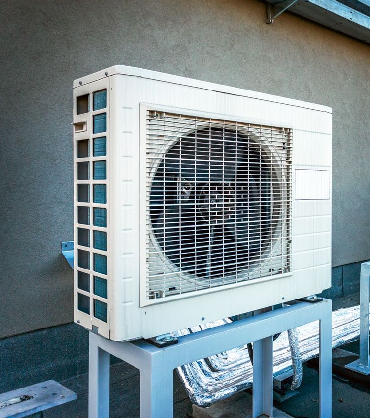
I     IDU   Indoor Unit                                      R       RAC     Refrigeration And Air Conditioning

      IEA   International Energy Agency                      S         SC    Sub Committee

      IEC   International Electrotechnical Commission               SCOP     Seasonal Coefficient Of Performance

      IKI   Internationale Klimaschutzinitiative                    SEER     Seasonal Energy Efficiency Ratio
            (International Climate Initiative)
                                                                 Split ACs   Split-Type Air Conditioning Systems
     IPCC   Intergovernmental Panel on Climate Change
                                                             T         TC    Technical Committee
    ISEER   Indian Seasonal Energy Efficiency Ratio
                                                                    TEAP     Technology And Economic Assessment Panel
      ISO   International Organization for Standardization
                                                                   TESDA     Philippines’ Technical Education And Skills
J   JARN    Japan Air Conditioning,                                          Development Authority
            Heating & Refrigeration News, Ltd.
                                                                      TEV    Thermal Expansion Valve
    JRAIA   Japan Refrigeration and Air Conditioning
            Industry Association                                      TFA    Trifluoro Acetic Acid

                                                                       ToT   Training of Trainers
L    LCIA   Lifecycle Impact Assessment
                                                             U        U4E    United For Efficiency
     LFL    Lower Flammability Limit
                                                                     UBA     Umweltbundesamt (German Environment
     LPG    Liquefied Petroleum Gas                                          Agency)

M   MEPS    Minimum Energy Performance Standards                      UFL    Upper Flammability Limit

      MIT   Mitigation                                              UNEP     United Nations Environmental Program

N   NAMA    Nationally Appropriate Mitigation Actions             UNFCCC     United Nations Framework Convention On
                                                                             Climate Change
      NC    National Committee
                                                                   UNIDO     United Nations Industrial Development
                                                                             Organization
    NDCs    Nationally Determined Contributions
                                                             W        WG     Working Group
     NOU    National Ozone Unit

O    ODP    Ozone Depleting Potential

     ODS    Ozone Depleting Substance

     ODU    Outdoor Unit
Q    QCR    Qualification, Certification and Registration

                                                                                                                           5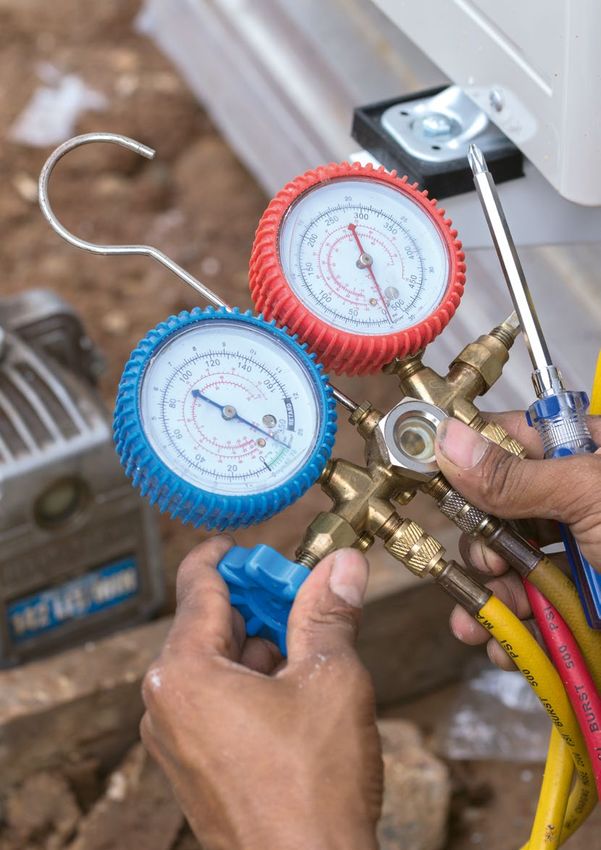
Foreword
Room air conditioning appliances become more and more This guide clearly shows that single-split room ACs
popular worldwide. 129 million units have been sold in equipped with R290 (propane) exhibit significant environ-
2017 (JARN, 2018), including roughly 100 million single- mental advantages through good energy performance and a
split air conditioners (ACs). Compared to the year 2007, GWP close to zero. The guide shall contribute to address-
this means a growth in sales of such appliances by 64% - in ing and demystifying all aspects relevant for the successful
only ten years. The reasons for this trend are a growing introduction of R290 split Air Conditioners.
world population, a rising middle class in countries with
emerging markets and, more recently, rising temperatures A good example that proofs the viability of this option comes
due to climate change. from India where a domestic manufacturer offers a single-
split air conditioner with R290 refrigerant. The product is
Ironically, the latter is caused to a considerable share by the most energy-efficient appliance of this product group on
air conditioning itself through the energy consumption the Indian market. More than 600,000 units have been sold
associated with the use of air conditioning equipment. to end users so far with no reported incidents because they
The International Energy Agency provides in a current are safely installed by qualified and certified personnel. This
report (IEA, 2018) that 20% of the energy consumption example should encourage other governments and manufac-
in buildings is due to air conditioning. Further, it projects turers to introduce their R290 solutions to the domestic and
that energy consumption in this field will more than triple worldwide market. Considering the phase-down of hydro
by the year 2050. This trend is driven mainly by the fluorocarbons such as R410A and R32 according the recent
residential sector where single-split AC appliances are the Kigali Amendment to the Montreal Protocol, which already
dominating type of AC equipment. Accelerated energy started with the first step of -10% of the baseline, R290 is
efficiency levels for these type of appliances in the short term today the only viable and future-proof choice for residential
are crucial to minimize or even decrease the currently and light commercial single-split air conditioning.
growing impact on the climate.
The significant climate impact of room ACs is not only
made by fossil fuel-based electricity supply, but also a result
of the predominant and massively growing use of halogen-
ated refrigerants such as R22, R410A, and, to a growing
extent, R32 with high global warming potential (GWP), Dr. Bettina Rechenberg
which today have a significant share of the overall green- Director General of Division III – Sustainable Production
house gas emissions caused by air conditioners. For single- and Products, Waste Management
split room ACs, the loss of the initial refrigerant charge German Environment Agency
over the lifetime is 100% or even more, caused through
leakages during operation as well as during installation
and disposal at the end of life. Therefore, the use of natural
refrigerants with very low GWP not only can result in
superior energy performance, but also lead to negligible
GHG emissions through refrigerant losses during service
and at the end of life.
6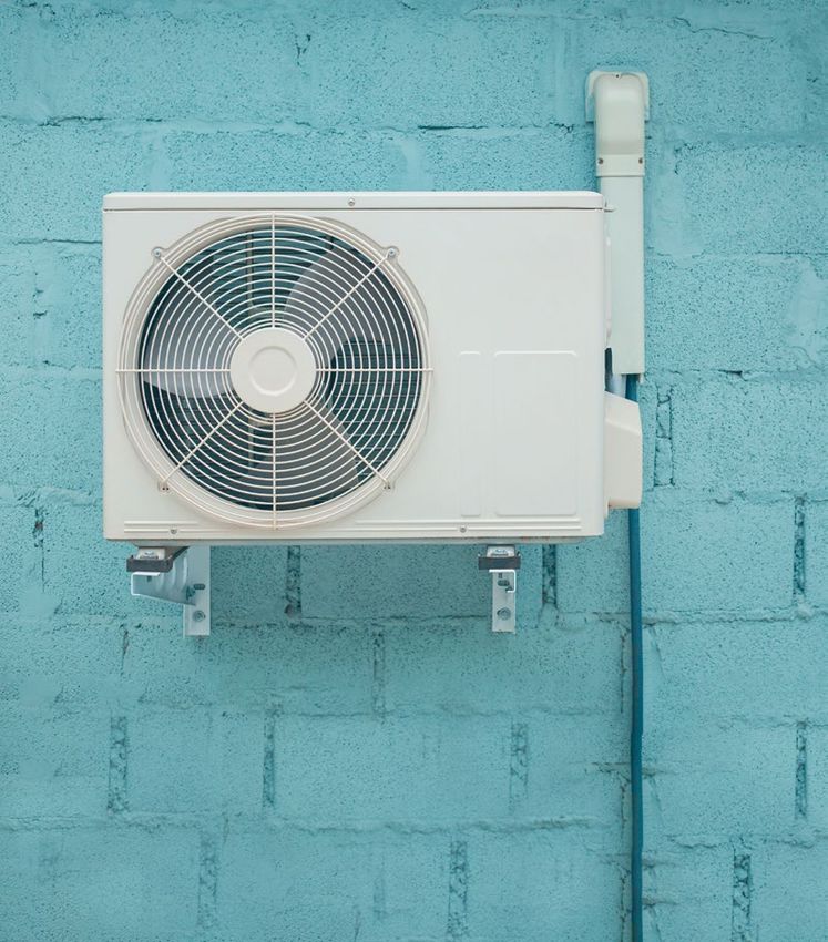
Purpose of this guide
Split-type air conditioning systems (split ACs) are currently the
most commonly used appliance for space cooling worldwide.
In many regions split ACs operate with average to low energy
efficiency levels and use highly climate-damaging refrigerants.
Large amounts of fossil fuel-based electricity is consumed
and leaking hydrochlorofluorocarbon (HCFC) and hydro
fluorocarbon (HFC) refrigerants often make them account
for a substantial proportion of greenhouse gas (GHG) emissions
in the refrigeration and air conditioning (RAC) sectors in
developing countries. This trend may become more signifi-
cant as the worldwide demand for split ACs is growing at a
rapid pace driven by increasing population, a rising middle
class, and urbanisation.
According to IEA (2018) estimates, space cooling accounted
for around 10% of total electricity demand worldwide in
2016. With business as usual, the energy demand from air
conditioners will more than triple by 2050. The increase in
absolute numbers of split ACs will be the most significant
from just over 850 million to over 3.7 billion.
Market assessments that GIZ carried out in numerous coun-
tries show that accelerating the transition to more energy-
efficient split ACs with R290 (propane) refrigerant will play
a key role in creating a more sustainable RAC sector. Leap-
frogging to high efficiency appliances using R290 reduces
the energy consumption and GHG emissions and thus
provides a significant opportunity to contribute to national
climate action plans (Nationally Determined Contributions
(NDCs)). Figure 1 and 2 on page 8 sketches different miti
gation scenarios for the market uptake of energy-efficient
R290 split AC units and depicts the total and direct GHG
emission reduction potential until 2050. A market share of
50% until 2050 may cut down total GHG emission by 25% and uncertainties about new technologies, as well as limited
by 20501. understanding of the proper treatment of the refrigerants in
the process of manufacturing, installing, operating, and dis-
While there is an urgent need for action in the sector, there posing of appliances. In addition, there is often a hesitance
are several barriers to a market transition, such as safety con- to invest in such technology, despite significant reduction
cerns about the flammability of R290, lacking awareness potential in energy costs.
1 Assumptions are based on studies by HEAT GmbH and GIZ. The trend of the
curves show that the market uptake of R290 split ACs will achieve
significant reductions in GHG emissions after 2025 when old inefficient
appliances reach their end-of life and the total share of R290 split ACs in
the overall stock increases to significant numbers.
7
3000
                                                                                                       BAU
              2500                                                                                     MIT_50 (R290 split AC share of 50%)
                                                                                                       MIT_70 (R290 split AC share of 70%)
              2000
Mt CO2eq

                                                                                                       MIT_90 (R290 split AC share of 90%)
              1500

              1000

               500

                  0
                      2015     2020     2025     2030      2035     2040      2045      2050

Figure 1: Total GHG emissions due to the use of split ACs (2015-2050)

               800
                                                                                                        BAU
               700                                                                                      MIT_50 (R290 split AC share of 50%)
                                                                                                        MIT_70 (R290 split AC share of 70%)
               600
                                                                                                        MIT_90 (R290 split AC share of 90%)
               500
Mt CO2eq

               400

               300

               200

               100

                  0
                      2015     2020     2025     2030      2035     2040      2045      2050

 Figure 2: Total direct GHG emissions due to the refrigerant leakage of split ACs (2015-2050)

 The objective of this resource guide is to inform relevant                This guideline intends to address knowledge gaps as well as
 stakeholders about the factors that are deemed crucial for a              the concerns that hinder the introduction and application of
 successful market transition to energy-efficient R290 split               R290 split AC. This guide tackles all topics relevant to R290
 ACs. The guide addresses:                                                 split AC and provides a set of references for more detailed
                                                                           information at the end of each chapter.
           Political decision makers who are confronted with
           energy efficiency and refrigerant policy making, and            The information in this guide is built on practical experience
           who would like to improve their understanding about             gained in GIZ Proklima projects (including IKI projects like
           R290 split ACs in order to take informed consultations          the conversion of Godrej & Boyce production line to R290
           with the industry and other relevant bodies.                    split AC in India, Cool Contributions fighting Climate
                                                                           Change, Green Chillers NAMA project Indonesia, Green
           National standardisation, custom and certification              Cooling Initiative) and interviews with industry players. The
           bodies that are tasked with the development and                 guideline is intended to enable key stakeholders to take
           issuance of standards on performance testing, product           effective and coordinated measures to introduce Green AC
           safety, and technician skills required for R290 split ACs.      technology in their country. Ultimately, it aims to encourage
                                                                           policy makers to facilitate the market uptake of energy-
            he split AC industry, including manufacturers, assem-
           T                                                               efficient split ACs using R290.
           blers, contractors, and installation companies, which are
           considering to transition or expand their business to
           manufacture, sales, and servicing of R290 split ACs.

 8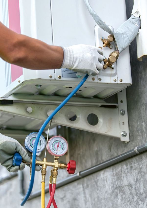
Content

1. Technical design and components of split AC .  .  .  .  .  .  .  .  .  .  .  .  .  .  .  .  .  .  .  .  .  .  .  .  .  . 12
     1.1. Working principle of room AC systems .  .  .  .  .  .  .  .  .  .  .  .  .  .  .  .  .  .  .  .  .  .  .  14
     1.2. Refrigerant characteristics  .  .  .  .  .  .  .  .  .  .  .  .  .  .  .  .  .  .  .  .  .  .  .  .  .  .  .           15
     1.3. Energy Efficiency Performance .  .  .  .  .  .  .  .  .  .  .  .  .  .  .  .  .  .  .  .  .  .  .  .  .  .  16

2. Technical particularities of R290 split ACs and their safety features  .  .  .  .  .  .  .  .  .  .  .  .  .  . 20
     2.1. R290 refrigerant  .  .  .  .  .  .  .  .  .  .  .  .  .  .  .  .  .  .  .  .  .  .  .  .  .  .  .  .  .  .  .  .      20
     2.2. Specific technical features for R290 split AC .  .  .  .  .  .  .  .  .  .  .  .  .  .  .  .  .  .  .  .  23

3. Manufacturing of R290 split ACs .  .  .  .  .  .  .  .  .  .  .  .  .  .  .  .  .  .  .  .  .  .  .  .  .  .  .  .  .  .  .  . 29

4. Safety standards for R290 split ACs  .  .  .  .  .  .  .  .  .  .  .  .  .  .  .  .  .  .  .  .  .  .  .  .  .  .  .  .  .  . 33
     4.1 Safety standards for R290 split AC unit  .  .  .  .  .  .  .  .  .  .  .  .  .  .  .  .  .  .  .  .  .  .              33
     4.2. Safety standards for performance and product safety testing of R290 split ACs .  .  .  .  .  38

5. Energy performance testing, standards and labels .  .  .  .  .  .  .  .  .  .  .  .  .  .  .  .  .  .  .  .  .  .  . 40
     5.1. Minimum Energy Performance Standards  .  .  .  .  .  .  .  .  .  .  .  .  .  .  .  .  .  .  .  .  .                   42
     5.2. Energy labelling  .  .  .  .  .  .  .  .  .  .  .  .  .  .  .  .  .  .  .  .  .  .  .  .  .  .  .  .  .  .  .  .      42

6. Eco-labelling of R290 Room ACs .  .  .  .  .  .  .  .  .  .  .  .  .  .  .  .  .  .  .  .  .  .  .  .  .  .  .  .  .  .  .  . 44

7. Installation and servicing of split ACs with flammable refrigerant  .  .  .  .  .  .  .  .  .  .  .  .  .  .  . 47
     7.1. Installation  .  .  .  .  .  .  .  .  .  .  .  .  .  .  .  .  .  .  .  .  .  .  .  .  .  .  .  .  .  .  .  .  .  .    48
     7.2. Servicing and repair .  .  .  .  .  .  .  .  .  .  .  .  .  .  .  .  .  .  .  .  .  .  .  .  .  .  .  .  .  .  .  48
     7.3. Decommissioning and disposal .  .  .  .  .  .  .  .  .  .  .  .  .  .  .  .  .  .  .  .  .  .  .  .  .  .  50
     7.4. Qualification, certification and registration of AC technicians .  .  .  .  .  .  .  .  .  .  .  .  .  50

                                                                                                                                  9
List of Tables

Table 1:    Overview of most common cooling capacity classes for single-split ACs, expressed in
            different metric units  .  .  .  .  .  .  .  .  .  .  .  .  .  .  .  .  .  .  .  .  .  .  .  .  .  .  .  .  .  .  .  .  .  .  .  .  .   13
Table 2:    Overview of refrigerants for split type ACs adapted from GIZ Proklima Input in U4E (2017) .  .  .  .  .  .  .  15
Table 3:    Availability of components related to EE for medium- and low-GWP
            refrigerants in AC (TEAP, 2019) .  .  .  .  .  .  .  .  .  .  .  .  .  .  .  .  .  .  .  .  .  .  .  .  .  .  .  .  .  .  .  .  .       17
Table 4:    Comparison of various thermo-physical properties of selected refrigerants  .  .  .  .  .  .  .  .  .  .  .  .  . 20
Table 5:    Commercial Specifications of the refrigerant according to standard AHRI 700 and DIN 8960. .  .  .  .  .  .  21
Table 6:    Technical safety features for R290 split AC units; adapted from adapted from GIZ Proklima
            (2008 & 2010); Caravatti, 2018  .  .  .  .  .  .  .  .  .  .  .  .  .  .  .  .  .  .  .  .  .  .  .  .  .  .  .  .  .  .  .  .  .       24
Table 7:    Summary of general technical obligations under safety standards for split AC systems  .  .  .  .  .  .  .  . 34
Table 8:    Refrigerant charge size limits for R290 according to safety standards for split ACs .  .  .  .  .  .  .  .  .  . 35
Table 9:    Minimum room size according to R290 refrigerant charge and installation height of the appliance
            based on Equation (2)  .  .  .  .  .  .  .  .  .  .  .  .  .  .  .  .  .  .  .  .  .  .  .  .  .  .  .  .  .  .  .  .  .  .  .  .  . 35
Table 10:   Overview of energy performance metrics and testing standards  .  .  .  .  .  .  .  .  .  .  .  .  .  .  .  .  .  . 40
Table 11:   Reference outdoor temperature bin distribution adapted from Indian Weather Data Handbook,
            2014 (BEE, 2015)  .  .  .  .  .  .  .  .  .  .  .  .  .  .  .  .  .  .  .  .  .  .  .  .  .  .  .  .  .  .  .  .  .  .  .  .  .  .  .   41
Table 12:   Overview of ISO 14024 ecolabels for split ACs . . . . . . . . . . . . . . . . . . . . . . . . . . .45

10
List of Figures
Figure 1: Total GHG emissions due to the use of split ACs (2015-2050) . . . . . . . . . . . . . . . . . . . . 8
Figure 2: Total direct GHG emissions due to the refrigerant leakage of split ACs (2015-2050) . . . . . . . . . . 8
Figure 3: Main components of IDU . . . . . . . . . . . . . . . . . . . . . . . . . . . . . . . . . . . . 12
Figure 4: Main components of ODU . . . . . . . . . . . . . . . . . . . . . . . . . . . . . . . . . . . . 13
Figure 5: Basic setup and operation of split AC cooling system using vapour compression cycle . . . . . . . . . 14
Figure 6: Comparison of fixed speed and inverter compressor behaviour (Godrej, 2018c) . . . . . . . . . . . . 16
Figure 7: Flammability range of R290 . . . . . . . . . . . . . . . . . . . . . . . . . . . . . . . . . . . 21
Figure 8: Principal design approach for explosion protection (Colbourne, R290 product development) . . . . . . 23
Figure 9: Example for label on IDU . . . . . . . . . . . . . . . . . . . . . . . . . . . . . . . . . . . . 26
Figure 10: Example for label on ODU . . . . . . . . . . . . . . . . . . . . . . . . . . . . . . . . . . . . 26
Figure 11: Exemplary set-up of an assembly line for non-flammable refrigerants and with safety areas
required for R290 specified (red triangles) split air conditioners ODU; adapted from (© AGRAMKOW) . . 30
Figure 12: Ventilation system of refrigerant gas charging station . . . . . . . . . . . . . . . . . . . . . . . 32
Figure 13: Gas detector at gas charging station . . . . . . . . . . . . . . . . . . . . . . . . . . . . . . . 32
Figure 14: Ventilation system and gas alarm of test performance lab . . . . . . . . . . . . . . . . . . . . . 32
Figure 15: ATEX certified control panel . . . . . . . . . . . . . . . . . . . . . . . . . . . . . . . . . . 32
Figure 16: Example of the relationship between refrigerant charge and cooling capacity as a
function of SEER of an AC system with R290 adapted from GIZ Proklima (2018b) . . . . . . . . . . . 33
Figure 17: Testing categories and its scope . . . . . . . . . . . . . . . . . . . . . . . . . . . . . . . . . 38
Figure 18: India’ mandatory energy label and star rating, valid from 01/01/2018 until 31/12/2019
(Source: BEE, 2015), 5-star label split AC with 5.8 ISEER and R290 refrigerant (Godrej , 2018b) . . . . . 43
Figure 19: Life cycle impact assessment of a single-split AC using R410A as the refrigerant (UBA, 2018) . . . . . 44
Figure 20: Formal procedure for Blue Angel . . . . . . . . . . . . . . . . . . . . . . . . . . . . . . . . 46
Figure 21: Arrangement of tools and potential temporary flammability zones adapted
from Godrej/Hühren (2018d) . . . . . . . . . . . . . . . . . . . . . . . . . . . . . . . . . . 49
Figure 22: Important steps to establish QCR infrastructure based on HEAT (2017) . . . . . . . . . . . . . . . 51
111. Technical design and
components of split AC
Demand for space cooling is growing rapidly due to a rising The most popular split-type air conditioning systems are
middle class, urbanisation, and climate change. Split ACs single-split ACs, also known as mini-splits. The single-split
already dominate the market share of space cooling appli- AC consists of two modules that are connected by refrigerant
ances in many markets and are projected to increase signifi- piping and electrical cables:
cantly in the next decades.
FAN
EVAPORATOR
REAR PANEL MOUNTING PLATE
FRONT PANEL
PCB BOX MOTOR
FILTER
MIDDLE PANEL
Figure 3: Main components of IDU
•
An indoor unit (IDU) including the evaporator (when • n outdoor unit (ODU) containing the compressor,
A
in cooling mode) and a fan that is mounted inside condenser (when in cooling mode), fan, and expansion
the air-conditioned room (Figure 3). device which is installed outside (Figure 4).
Worldwide, split ACs are mostly used for cooling purposes reversible system. This guide focuses on the cooling purpose.
only and therefore usually just non-reversible systems are In addition to single-split AC systems, the market offers
needed. In more moderate climates, split AC technology is multi-split AC systems comprising one ODU linked to sev-
offered which combines cooling and heating mode in one eral IDUs. Multi-split systems may be suitable for space
12cooling (or heating) of multiple rooms or large rooms. commercial areas such as hotels and supermarkets. The rela-
This guide focuses on single-split units because they are tively low investment, simple installation, and low space
the most commonly used system for residential customers requirement are main advantages of single-split ACs.
and are also widely employed in office spaces and
TOP COVER
CONDENSER
FAN MOTOR
FRONT PANEL
SIDE PANEL
FAN
COMPRESSOR
Figure 4: Main components of ODU
The available cooling capacity classes for single-split ACs and end-user requirements. The cooling capacity classes are
range roughly from 1.8 to 7 kW (6,000 to 24,000 Btu/h). expressed in different metrics units depending on the con-
The suitable cooling capacity is defined by the actual space sidered country or region. The most common classes are
cooling demand taking into account room size, heat load, listed in the following conversion Table 1:
Common Cooling Capacity Classes
1.76 kW 2.64 kW 3.52 kW 5.28 kW 7.03 kW
6.000 Btu/h 9,000 Btu/h 12,000 Btu/h 18,000 Btu/h 24,000 Btu/h
0.5 RT [1] 0.75 RT 1 RT 1.5 RT 2 RT
Table 1: Overview of most common cooling capacity classes for single-split ACs, expressed in different metric units
[1] RT: Refrigeration ton (or ton of refrigeration), 1 RT equals 12,000 British
thermal unit (Btu)/h refrigeration capacity
131.1. Working principle of room
AC systems
The cooling technology is based on the common vapour from the metal of the evaporator coil. The circulating room
compression refrigeration cycle as illustrated in Figure 5. air is cooled accordingly. Once the refrigerant has been
It mainly comprises four components: evaporator, compres- vaporised, it is drawn through the suction line into the
sor, condenser, and an expansion device. compressor. The compressor compresses the vapour and
thus raises the pressure to a value corresponding to the
The refrigeration cycle contains liquid refrigerant at high saturated vapour temperature, which lies above the tem-
pressure in the liquid line passing through an expansion perature of the surrounding air. The high-pressure refrigerant
device (restrictor), which typically could be a capillary tube vapour now passes through into the condenser (which may
(for most split air- conditioner) or an expansion valve. Here be a finned tube or microchannel heat exchanger), where it
the refrigerant pressure is reduced abruptly causing a part is condensed back into a liquid state thereby rejecting the
of the liquid to immediately vaporize. This effect lowers energy it absorbed in the evaporator and compressor to the
the temperature of the liquid-vapor refrigerant mixture ambient air. The high-pressure liquid refrigerant now moves
below the surrounding air temperature. The cold mixture to the bottom of the condenser coils. To complete the refri
is then routed through the injection line into the evaporator. geration cycle, it is transferred back into the refrigerant
The liquid part of the refrigerant mixture begins to evaporate liquid line.
by absorbing heat from the surrounding, which is transferred
Heat Release
Liquid Gas
Condenser
Liquid line Discharge line
High Pressure
Strainer
Expansion
device (capillary tube) Compressor
Service valve
Service valve
with service port
Low Pressure
Injection line Suction line
Evaporator
Heat absorption
Figure 5: Basic set-up and operation of split AC cooling system using vapour compression cycle
141.2. Refrigerant characteristics
Currently, the most common refrigerants for split ACs are warming potential (GWP) and are subject to the HFC
R22, R410A, and R32. The ozone-depleting R22 is subject phase-down under the Kigali Amendment to the Montreal
to the ongoing international HCFC phase-out under the Protocol. The gradual reduction of HFCs to 10-20% of
Montreal Protocol. Non-Article 5 (developed countries ) the baseline by the late 2040s has been agreed. On 1st of
countries have fully phased out HCFCs as refrigerant in January 2019, the Kigali Amendment entered into force.
new units and the phase-out in Article 5 countries (devel- The first reductions by non-Article 5 countries is due in
oping countries) will be completed by 2030. R22 is pri- 2019. Article 5 countries will follow with a freeze of HFC
marily replaced by the HFC mixture R410A (50% R32 consumption levels in 2024 and for some countries in
and 50% R125) and R32. Both are HFCs with high global 2028.
Low GWP HFC/
Refrigerant R22 R410A R32 HFO blends R290
GWP 2 1,760 1,924 677 150 – 300 3
Refrigerant Efficiency High Low High Medium High
Cost of Low/Medium Medium/High Medium High Low
refrigerant3
Subject · Substance · No · Yes · No · Yes · No
to · Production · Yes · No · Yes · Yes · No
patent · Systems · Yes · Yes · Yes · (Probably) · Yes
on:
ISO 817 safety A1 – lower toxicity A1 – lower toxicity A2L – lower toxicity A2L to A3 – lower A3 – lower
Classification and non- and non-flammable and lower toxicity and lower to toxicity and higher
flammable flammability higher flammability
flammability
Other environemental HF, HCI and CO2 HF and CO2 HF and CO2 TFA, HF and CO2 H2O and CO2
impact/ degradation
products 4
Training General safe General safe General safe General safe General safe
requirements handling of handling of handling of refrig- handling of refrig- handling of refrig-
refrigerants; refrigerants erants; Training and erants; Training and erants; Training and
certification of certification of certification of
Responsible han- manufacture and manufacture and manufacture and
dling of ODS service technicians service technicians service technicians
on flammable on flammable on flammable
refrigerants refrigerants refrigerants
Use restrictions/ Subject to HCFC Restricted use or Restricted use or Restricted use or No ban
implications phase-out ban in regions with ban in regions with ban in regions with
GWP based HFC GWP based HFC GWP based HFC
phase out regimes phase out regimes phase out regimes
(e.g. EU-F-Gas) (e.g. EU-F-Gas) (e.g. EU-F-Gas)
Table 2: Overview of refrigerants for split type ACs adapted from GIZ Proklima Input in U4E (2017)
2 Intergovernmental Panel on Climate Change (IPCC) 5th Assessment Report, 4 Survey of selected fluorinated GHGs, Danish Ministry of the Environment,
2013 2014; and according to comments received by Prof. Dr. Andreas Konrath
3 While these are indicative of current costs, future costs of R290, R32 and
low-GWP blends will depend significantly on the scale of production due to
the Kigali Amendment to the Montreal Protocol, and may be lower if
sufficient scale is achieved.
151.3. Energy efficiency performance
Compressor performance and size of heat exchanger largely These technologies aim to increase the amount of
determine the overall system energy efficiency of split ACs, heat transferred per m2 of exchanger area or per m3
so these components need to be targeted primarily to im of exchanger volume, thereby reducing the approach
prove energy efficiency. Optimisation of the heat exchanger temperature difference between air and refrigerant.
for condenser and evaporator can be achieved through
increasing the surface area and the choice of material. For Introducing a variable-speed compressor also results in
instance, use of: energy savings, as the technology can adapt system cooling
capacity to part loads with slight changes in cooling demand.
• O ptimised fin arrangements and geometries Unlike fixed speed AC compressor which operates in an
• Turbulators/extended internal tube surfaces on/off mode, the speed of the compressor motor changes in
• Extruded micro-channels. proportion to the difference between set temperature and
the actual room temperature.
Temp
Too hot Too hot
Comfortable
Set temp.
Time
Small Temp
Diff.
INVERTER
Start up Cold
Cold NON-INVERTER
Figure 6: Comparison of fixed speed and inverter compressor behaviour (Godrej, 2018c)
Furthermore, a careful selection of the compressor capacity The online platform TopTen publishes a list of the best
according to the cooling need and an appropriate refrigerant currently available split ACs in terms of energy efficiency
charge to ensure operation under the most favourable in Europe and China. Park et al. (2017) and GIZ Prok-
thermodynamic conditions can also have a significant effect lima (2018a) have conducted studies to assess the cost,
on the performance. A selection of efficiency measures are energy, and climate performance of the available equip-
presented in Table 3 and further details on improvement ment in relevant additional markets.
options are compiled by Usinger (2016).
16Table 3: Availability of components related to EE for medium- and low-GWP refrigerants in AC (TEAP, 2019)
Applicability to
Max climate region
Applicable potential Incremental
to ref Available Presently Necessary improve- cost for
Component circuit today? in use? Remarks components ment RAC unit LAT MAT HAT
Compressors
Mostly
Higher
X Y Y used for X X X
efficiency
rotary
Mostly Inverter,
-Inverter
X Y Y used for dedicated 20% to 30% 20% X X X
driven
rotary compressor
Very
- two stage
X Y L limited 10% 10% to 20% X X X
compression
availability
- motor
efficiency Y L Standard same same X X X
controllers
Energy-efficient fan mators
Reduce
- EC fan
Y Y energy, Controller 7% to 15% 15% to 25% X X X
motors
heat load
- variable/
Y Y X X X
fixed-speed
- optimized fan
Y Y X X X
blades
-tangential For indoor
Y Y X X X
fans unit only
For
- improved
Y Y outdoor X X X
axial fans
unit only
Expansion devices
- electronic
EEV and
expansion X Y L 15% to 20% 15% X X X
controller
valves
RAC Less
-fixed orifice X Y L negative X X X
heating efficiency
- capillary Heating
X Y Y TEV negative X X X
tubes mode
17Applicability to
Max climate region
Applicable potential Incremental
to ref Available Presently Necessary improve- cost for
Component circuit today? in use? Remarks components ment RAC unit LAT MAT HAT
Heat exchangers
-Microchannel Only
Y Y Y AL/AL 15% negative X X X
condenser coil condenser
Less cost
-Microchannel compared
N N N
evaporator coil to the fin
and tube
- smaller tube
diameter for X Y Y Y CU/AL 10% to 40% negative X X X
condenser coil
- smaller tube
diameter for Y Y Y CU/AL 10% to 40% negative X X X
evaporator coil
Filter and
Adiabatic Very Only in high
Y water 25% to 30% 20% to 35% X
condensers limited ambient
treatment
Pipe Normal Pipe
Y YMARKET INTRODUCTION
OF GREEN ACs IN GHANA
Ghana has committed itself to abating climate-damaging
refrigerants such as R22 and R410A from its AC market
and transitioning instead to natural refrigerants by including
the RAC sector in its NDCs to the United Nations Frame-
work convention on Climate Change (UNFCCC) Paris
Agreement. By increasing the market share of energy-efficient
ACs using climate-friendly refrigerants, it is estimated that
about 7.86 Mt CO2 could be avoided by 2030.
The Green Cooling Initiative (GCI) is supporting the Environ
mental Protection Agency (EPA) in preparing the market
“Transitioning the market from R22 and R410A directly to introduction of energy-efficient R290 split ACs in Ghana.
R290 as a sustainable solution for Ghana’s growing AC In cooperation with the local AC dealers, the project is
market is promoted as one of the key climate measures in currently introducing 380 R290 split ACs to the market.
Ghana’s Climate Action Plans.” To ensure the safe market introduction of this new techno
logy in Ghana, Midea, and GIZ have jointly trained the
Emmanuel Osae-Quansah, Head of climate change and AC dealer’s technicians to safely handle this new but
Ozone department, National Ozone Officer, Environmental flammable refrigerant during installation, servicing, and
Protection Agency Ghana repair.
Midea representative providing lectures on
R290 split AC to Ghanaian technicians
as part of the market introduction in 2018
© GIZ Proklima/ Asiedu Danquah
192. Technical particularities
of R290 split ACs and their
safety features
In order to start adopting a new AC refrigerant, manufactur- constitutes some particularities for the system design. The
ers have to balance different refrigerants’ criteria, including flammability of propane presents the key challenge. This
thermodynamic performance (e.g. capacity, temperature, has to be considered during the development of the system
and efficiency), safety conditions (e.g. pressure, toxicity, to ensure the safety.
and flammability), and compatibility with system materials,
availability, cost, and environmental impact (Park et al.,
2019) as well as commercial lifetime, which is influenced
by (international) regulations and cost implications.
The use of R290 as refrigerant for a single-split AC system
2.1. R290 refrigerant
The hydrocarbon propane (C3H8) is a naturally occurring In general cycle efficiency is influenced by properties
gas. Through the decomposition and reaction of organic which help to reduce pressure losses and improve heat
matter over long periods of time, a variety of hydrocarbons transfer. Specifically, these include:
are in the depth of the earth. Propane can be separated
from other petrochemicals and refined for commercial use. • Low liquid and vapour viscosities
As a liquefied petroleum gas (LPG), propane can be converted • High liquid specific heat
to liquid under relatively low pressures. • High liquid and vapour thermal conductivities
• High latent heat.
Thanks to its favourable thermodynamic properties, propane
can be used as an energy-efficient refrigerant and has been It can be seen that across these common refrigerants,
assigned the refrigerant designation “R290”. Table 4 lists R290 exhibits the most desirable properties.
various thermophysical properties of certain refrigerants
as a means of comparing their potential to achieve high
efficiency.
Refrigerant Critical Liquid Vapour Liquid Liquid thermal Latent heat
temperature viscosity viscosity specific heat conductivity (kJ/kg)
(°C) (Pa s x106) (Pa s x106) (kJ/kg K) (W/m K)
R22 96.1 216 11.4 1.17 0.095 205
R407C 86.0 211 11.3 1.42 0.096 210
R410A 71.4 161 12.2 1.52 0.103 221
R290 96.7 126 7.4 2.49 0.106 375
Table 4: Comparison of various thermo-physical properties of selected refrigerants
20A high degree of purity and a very low water content have commercial refrigerant. Respective requirements are sum-
to be guaranteed in order for it to be suitable as marised in Table 5.
Standard Property Limit Value
AHRI 700 DIN 8960
Composition:
Propane ≥ 99.5% Weight ≥ 99.5% Volume
C3 and C4 saturated hydrocarbons ≤ 2% Weight
Isobutane ≤ 0,44% Volume
n-butane ≤ 0,15% Volume
unsaturated C4 compounds ≤ 0,01% Volume
Smell None
Water Content ≤ 10 ppm Weight ≤ 12 ppm Weight
Table 5: Commercial specifications of the refrigerant according to standard AHRI 700 and DIN 8960
With a safety classification of “A3” under ISO 817, R290 becomes flammable within a certain concentration range
is generally of low toxicity but is flammable. R290 only in the air. The range is illustrated in Figure 7.
Lower Flammability Upper Flammability
Limit (LFL) Limit (UFL)
2.1% HC refrigerant 9,5% HC refrigerant
Pure (100%) air Pure (100%) HC
refrigerant
Figure 7: Flammability range of R290
For safety reasons, some fraction of the lower flammability Further, it is odourless so it cannot be detected by smell.
limit (LFL) should not be exceeded in closed spaces or This must be taken into account when determining the
rooms. Previously a value corresponding to one-fifth of the quantity of R290 permitted; specific approaches for
LFL (or “practical limit”) was used in EN378-Part 1, identifying such limits are addressed in Chapter 4.
but now as safety concepts are advancing, the value differs A flammable mixture only ignites, if there is a sufficient
depending upon which concept is to be adopted. energy source to start the reaction such as a spark, an open
flame or a hot surface. Combustion of R290 will result in
Integrated into these safety concepts is the recognition various combustion products, primarily carbon monoxide
that R290 is heavier than air, which means that it will (CO), carbon dioxide (CO2), and water (H2O). A fire with
accumulate near the ground in the event of a leakage. R290 should only be fought with CO2 or dry powder
extinguishers.
21Safety guidelines are not only applicable during the design • Correct naming and distinct “flammable” marking
phase (Chapter 2.2) and production phase (Chapter 3) of a on cylinders and transaportation vehicles
split AC but also regarding storage, transport, and instal • Store and use in ventilated areas away from ignition
lation area of the equipment. sources (avoid exposure to heat, no smoking)
• Safe transportation in upright, capped and secure
position (protect valve)
Safe handling of refrigerant cylinders • Use of goggles and gloves when handling R290 to
For handling and transporting R290 cylinders, ideally minimise the possibility of frost bite from contact
local regulations for liquefied petroleum gas (LPG) have to with liquid as with handling any other refrigerant.
be followed. If there are none, at least the following mea-
sures have to be taken in order to prevent any accidents:
Local production and supply of R290
in Indonesia by PT Pertamina
In Indonesia, state-owned oil and natural gas corporation, The company has supplied refrigerant for several hydro
PT Pertamina, is a local producer and supplier of propane. carbon chillers and expects a growing supply of R290 AC
At their refinery in Palembang, LPG is extracted from crude appliances
oil and then used as fuel gas. Through further purification
steps, propane is also processed to suitable industrial gas as
well as refrigerant gas. At three filling stations in Indonesia, Filling station for R290 refrigerant in Jakarta,
R290 is bottled and then distributed across the country. Indonesia (© PT Pertamina)
222.2. Specific technical
features for R290 split AC
Due to safety considerations, the design adjustments The safety design consists of improved tightness, elimination
mainly deal with minimising the charge size while main- of ignition sources, measures to enhance dispersion of leaked
taining high energy efficiency. Using R290 as refrigerant refrigerant and risk mitigation measures. Figure 8 illustrates
requires manufacturers to optimise AC systems by changing the principal considerations for explosion protection when
compressors and compressor oil, heat exchangers (to match applying flammable refrigerants.
the refrigerant’s properties), and expansion device (Park et
al., 2019). The combination of the favourable thermo In particular, the technical features, shown in Table 6
dynamic properties of R290 and improved heat exchanger should be included for a R290 split AC to optimise the
design allows the minimisation of the refrigerant charge operational safety:
compared to conventional refrigerants.
Identify of Hydrocarbon refrigerant
dangerous substances
STEP 1:
Avoidance Characterise possibility of Leak simulation test,
of flammable flammable regions dispersion calculations
atmospheres
Limit the extent of flam- Reduction of charge size, ventilation,
mable regions leak reduction
STEP 2: Identify of potential
Elimination of Electrical components
sources of ignition
ignition sources
Eliminate or protect Protective enclosures,
potential sources of ignition selection of devices
STEP 3: Estimate the severity
Risk analysis
Limiting the of consequences
consequences of
ignition
Adopt features to minimise Gas detection, enclosure design,
the severity of ignition signage
Figure 8: Principal design approach for explosion protection (GIZ Proklima & TÜV Süd, 2010)
23Ensure good system tightness
Design and manufacture the refrigerant circuit with as many features as possible to minimise the possibility of refrigerant
leakage within the occupied space(s). For example:
• No detachable joints (particularly for IDU)
• Brazed connections (e.g. instead of flare joints)
• Protect from external mechanical damage
• Minimise transmission of vibrations from compressor, fans, etc.
• Avoid possibilities for corrosion
• Use approved circuit components
• Rigorous production and quality control
• Leak detection test proved tightness of components, piping, and connections.
Avoid potential sources of ignition associated with appliance
Design and construct the AC to ensure that if a leak was to occur, refrigerant would not be exposed
to any potential source of ignition associated with the unit. For example:
• Replace components with non-sparking or Ex-type parts5
• Use plastic instead of metal fan blades and a brushless electric motor to avoid sparks from contact with cowling panels
• Put main contactors in separate panels or use solid state contactors
• Encapsulate relays
• Any hot or sparking components are positioned away from wherever any refrigerant leak could flow to or accumulate,
typically by means of a leak simulation test.
Add leak detection
Some form of gas leak detection system may be integrated into the product so that flammability mitigation measures can
be activated. For example:
• Gas detector
• Ultrasonic receiver that detects the sound produced when a leak occurs with sonic flow
• Monitor system parameters (pressure, temperature, compressor current, etc.) that indicates a deficit of charge.
When a leak is detected, initiate protective measures, such as terminating compressor operation, switching on the IDU
and ODU blowers and/or closing safety solenoid valves to prevent all the refrigerant from being released.
5 According to IEC 60079-series
24Enhance dispersion of leaked refrigerant
• Ensure sufficient air flow rate to dilute R290 in the event of leakage
• Optimise unit housing design so that exiting concentration is minimised.
Minimise refrigerant charge
• Minimise the flammable refrigerant charge quantity while retaining high energy efficiency e.g. minimise coil bends
and use of smaller tube diameters for heat exchangers.
Use of solenoid shut-off valves
• In the event of a leak, a shut-off valve in the liquid or delivery line and where necessary in the suction line can close
in order to prevent flow of refrigerant from ODU to the possible leak hole in the IDU.
• During off-mode valve(s) could be normally closed so that the refrigerant is automatically prevented from flowing
towards the leak.
Inform about flammable refrigerant
nsure that anyone initiating work on the system is made aware of the presence of flammable refrigerant inside and
E
as far as possible the precautions they should take.
• Flammable refrigerant signage visible on indoor and outdoor unit
• Flame symbol and instruction manual symbol on parts subject to maintenance or repair
• Warning label for room requirement
• Installation/service/operation manual
• Signage and instruction for transportation on packaging
for pre-charged equipment.
Table 6: Technical safety features for R290 split AC units; adapted from (adapted from GIZ Proklima (2010) & Caravatti (2018))
25As addressed above, the split AC system has to be specifically designed to ensure minimal risk due to the flammability of R290. Using R290 as drop-in refrigerant for existing R22 systems or any other system poses a greater safety risk as the appropriate technical features are not necessarily in place. Additionally, drop-ins might affect the efficiency and lifetime of system components such as compressors, which are designed for particular refrigerants and their properties. Therefore, simply refilling existing HCFC or HFC refrigerant-based appliances with R290 is strongly advised against. In addition, any split AC needs to have a specification plate on both indoor and outdoor unit. These labels provide important technical information to any AC technician working on the system. Figure 9 and Figure 10 show examples for the required information on the labels. Figure 9: Example for label on IDU Figure 10: Example for label on ODU 26
References and relevant resources:

Split AC market assessment                     GIZ Proklima (2018), Cost, energy and climate performance assessment of split ACs in Asian
                                               Countries (market assessment for other countries in Africa and Latin America available upon
                                               request)
                                               Park, Shah and Gerke (2017), Assessment of commercially available energy efficient room air
                                               conditioners including models with low global warming potential (GWP) refrigerants (study
                                               by Lawrence Berkeley National Laboratory; focus on China, Europe, India, Japan, South Korea,
                                               and the United States)
                                               Best available air conditioners in Europe (TopTen EU) and in China (Top10 China)

Technical Safety Features for R290 split ACs   GIZ Proklima (2010), Guidelines for the safe use of hydrocarbon refrigerants, Part 5: Equipment
                                               Design and Development
                                               GIZ Proklima (2012), Natural Refrigerants: Sustainable Ozone- and Climate-Friendly
                                               Alternatives to HCFCs, II. Safety of Natural Refrigerants p. 95f

Technical Safety Features for R290 split ACs   GIZ Proklima (2010), Guidelines for the safe use of hydrocarbon refrigerants Godrej, Training
                                               Manual for Godrej Split Air-Conditioners with Hydrocarbons (R290 refrigerant), Chapter 3.1
                                               (available upon request)

                                                                                                                                                 27
LOW-CARBON AIR CONDITIONING
THROUGH R290 SPLIT ACs
IN COSTA RICA
Costa Rica is a global model and front-runner in transition-
ing to climate-friendly technologies and practices. Never-
theless, the use of advanced space cooling technology with
low-GWP refrigerants has not been well established in the
market. This can also be seen in the RAC sector’s significant “In a changing world, where the industry seeks day to day to
share of 12% (in 2012) of the country’s total GHG emissions. meet the technological needs of people, to be at the forefront
By using propane instead of HFC refrigerant in AC systems, of new options is essential. Costa Rica has taken important
Costa Rica can significantly reduce its HFC emissions and steps in this line on issues such as: renewable generation,
thereby further contribute to its ambitious low emission electric vehicles, and decarbonisation of the economy. Now
development path. it is time to take the step to new options of air conditioning
where R290 refrigerant will be an indisputable protagonist.
As part of the Cool Contributions fighting Climate Change It will be indispensable for our country to know all the bene-
(C4) Project in Costa Rica, the Ministry of Energy and fits of this gas and to be trained in its use and its applications.”
Environment in cooperation with the GIZ imported energy-
efficient R290 split ACs for demonstration and trainings of Marvin Donel Zuñiga Alvarez, Engineer from Ensayos,
AC technicians. The appliances are installed in various types Laboratory of Energy Efficiency
of buildings, including hotels and government buildings.
The project is implemented in a close cooperation with
ICE, one of the national electricity utilities in Costa Rica.
More information on the project can be found on:
https://www.international-climate-initiative.com/en/nc/
details/project/cool-contributions-fighting-climate-change-
c4-15_I_242-452/ Costa Rican technicians installing Godrej R290 split AC at the Climate
Change Office of the Ministry of Environment and Energy (MINAE)
28
© GIZ Proklima / Gianfranco Vivi3. Manufacturing
of R290 split ACs
Basic Set-Up
Up to now the actual production of R290 split ACs is still Figure 11 illustrates the exemplary set-up of a split AC pro-
low compared to the global volumes of split AC unit sales. duction line. The main components to assemble R290 split
The capacity to manufacture R290 units is so far limited AC units are identical with any other split AC factory, so
to China and India. There are over 20 production lines the conversion of existing conventional production lines for
already converted to manufacturing R290 split ACs. In R22 or R410A technology can be realised with relatively
India, the local manufacturer Godrej & Boyce (hereafter: little investment.
Godrej) is commercially producing R290 split ACs - mainly
for the domestic market – with approx. 650,000 units sold The main changes are related to incorporating and rein-
until July 2019. Several Chinese manufacturers transformed forcing safety measures with regards to handling flammable
their production lines in the past, among them Midea, Haier, refrigerant in the facility. Areas where R290 is stored,
TCL, Gree, Hisense, Changhong, AUX, and Yair. A large charged or handled demand for specific risk mitigation
number of portable/movable room ACs are being produced strategies. The hazardous areas are highlighted in Figure 11.
with R290. Safety measures include a good ventilation system, gas
detection, and alarm, warning signs as well as a complete
During the first stage (2013 to 2015) of China’s HCFC and automatic shut off in case of an emergency. The key
Phase-out Management Plan (HPMP) with funds of the areas in the R290 production line should be equipped with
Multilateral Fund, China has already converted 21 room real-time monitoring systems and set with alarms of differ-
AC production lines to R290 making up for a production ent levels. Appropriate training of the personnel to raise
capacity of 4,500,000 units per year. Three room AC com- awareness of the risk and to instruct them on how to avoid
pressor production lines have been also converted to R290 dangerous situations is an essential complement along with
with a production capacity of 5,400,000 units per year. the hardware equipment. In addition, assessments need to
China is in the process of converting another 20 room AC be undertaken in all areas of the production line to identify
production lines and another four room AC compressor and avoid ignition risks caused by electrostatic charges.
production lines to R290 as a part of the second stage of
China’s HPMP until 2020 (hydrocarbons21, 2018). In specific, the following set-up including relevant safety
features is recommended (GIZ Proklima, 2012):
Other countries, e.g. Egypt (8 production lines), Pakistan,
Brasil, etc. are about to convert productions lines under • Gas sensors and alarm systems
their stage II HCFC phase out management plans (HPMPs) • Ex-type electrical hardware in areas handling
of the Montreal Protocol. refrigerant
• Ventilation system in areas handling refrigerant.
Among the areas where specific safety measures need to be
added for R290 are:
• Refrigerant storage area
• Refrigerant charging system
• Ultrasonic sealing of process tube
• Leak detection after charging
• Product performance test chamber and laboratory
• Product repair area.
References and relevant resources:
Technical Safety Features for production line of GIZ Proklima (2012), Guidelines for the safe use of flammable refrigerants in the
R290 split ACs production of room air-conditioners
Finance Support for conversion of production GIZ Proklima (2018c), Coordinating finance for sustainable refrigeration and air conditioning
line
291. Srew Removal, 2. Brazing 3. H
igh Pressure Testing 4. Refrigerant Charging 5. U
ltrasonic Tube Sealing
Earth Wiring, Helium Leak Test
Compressor Fitting
306. L eak Detection 7. H
igh Voltage Testing 8. Case Fitting 9. Performance Testing 10. Visual Inspection
after Charging Lab/ Operational Packaging
Inspection
Figure 11: Exemplary set-up of an assembly line for non-flammable refrigerants and with safety areas required for R290 specified
(red triangles) split air conditioners ODU; adapted from (© AGRAMKOW)
31Production line conversion of R22 split AC to R290 split AC for Godrej
In 2012, Godrej converted one of its production facilities to assemble ODUs for R290 split ACs with
support of GIZ Proklima. The area is equipped with the following equipment:
• R290 gas charging station and performance test chamber including ventilation ducting with
two speed options as well as a gas alarm mechanism (placed on the ground) with complete power
cut-off interlock.
• Repair area refrigerant gas recovery system with ducting and gas alarm interlock.
• Fire proof junction boxes in refrigerant charging areas.
• Equipotential grounding of all equipment has been done.
Figure 12: Ventilation system of refrigerant gas Figure 13: Gas detector at gas charging station
charging station
Figure 14: Ventilation system and gas alarm of test Figure 15: ATEX certified control panel
performance lab
324. Safety standards
for R290 split ACs
4.1. Safety standards for R290
split AC unit
The introduction of split ACs with R290 requires a set of Each of these standards prescribe a number of requirements,
technical standards, which adequately address both flam- one of the most important critical ones for the application
mability/charge size and energy efficiency. There are two of R290 in split AC systems being the refrigerant charge
international standardisation organisations that publish size limit. Charge sizes of split AC systems with flammable
relevant safety standards with regard to the use of R290 in refrigerants need to be optimized in order to maintain
split-type ACs: The International Standardisation Organisa- acceptably low flammability risk safety levels while ensuring
tion (ISO) and the International Electrotechnical Commission high energy efficiency. Figure 16 provides an illustration of
(IEC). ISO 5149-1 and European Norm (EN) 378 are how the nominal cooling capacity of an AC system is
horizontal standards or product group standards covering related to its refrigerant charge for a range of different seasonal
overarching requirements based on common characteristics energy efficiency ratios (SEERs). The diagram highlights the
for a range of Air Conditioning, Refrigeration and Heat interdependence of system performance and required
Pump (ACR&HP) systems. The product standard IEC refrigerant charge. In general, it can be concluded that a
60335-2-40 specifically defines requirements for ACs and higher energy efficiency requires higher charge size.
heat pumps.
1000
SEER = 7
900
SEER = 8
800 SEER = 9
700 SEER = 10
R290 charge [g]
600
500
400
300
200
100
0
2 3 4 5 6 7
Nominal cooling capacity [kW]
Figure 16: Example of the relationship between refrigerant charge and cooling capacity as a function of SEER of an AC
system with R290 adopted from GIZ Proklima (2018b)
33Current requirements for systems using flammable
refrigerants
ACR&HP safety standards deal with a wide range of into the scope of a product standard, then that standard
hazards associated with ACR&HP systems and equipment, should be used. However, if a horizontal/group standard is
besides refrigerant charge issues. Aspects related to refrigerant more up to date and can be suitably applied to the product
safety and the associated design, construction and handling then it can also be applied. Often manufacturers may
requirements represent a large share of the addressed hazards. “mix-and-match” as appropriate. Further, it has to be noted
Table 7 provides a summary of the important topics handled that both standards are currently under revision and might
by ACR&HP safety standards that are relevant for the use contain changes regarding charge size and safety measures
of hydrocarbons in split ACs. Generally, if a product falls in the next version.
Category IEC 60335-2-40
EN 60335-2-40
Scope Factory-made whole ACs, heat pumps, dehumidifiers, and partial units
Limits on refrigerant charge Approx. 1 kg of hydrocarbon in a direct system inside (depending on room size) and 5 kg
amount outside or special enclosure
Marking Requirement of flammability warning symbols
Strength pressure Specification of pressure tests for systems and components (where applicable)
Electrical equipment Specification of design, construction, and test requirements
Sources of ignition Description of what to consider and how to avoid a potential source of ignition,
including a test method option
Information & instructions Details concerning the installation, use, service, maintenance, and disposal of the equipment
so that users, operators, and technicians are aware of how to handle flammability hazards
System tightness Systems generally have to be constructed as “sealed” or “hermetically sealed” systems if they
are to use flammable refrigerants indoors (e.g. no or limited number of reusable mechanical
connections or fittings)
Pressure limiting/ relief devices The need for additional devices to limit or relieve excess pressure may apply to smaller systems
if flammable refrigerants are used
Secondary/ indirect systems Additional components for secondary or indirect refrigerant circuits (such as those using water or brine)
are required to vent a leak that has occurred from the evaporator into the secondary circuit if the primary
refrigerant circuit exceeds a certain charge size
Gas sensors Gas sensors are be mandated for certain situations to initiate mitigation measures such as
ventilation, alarms, terminating electrical supplies, etc. These may be applicable to systems
using flammable refrigerants in machinery rooms or even for systems in occupied spaces.
Table 7: Summary of general technical obligations under safety standards for split AC systems6
As demonstrated in Table 8 and 9, the choice of refrigerant charge size limits should be met as they are ultimately the
type affects the requirements for several design and con- most important requirements within safety standards in
struction aspects. Accordingly, such requirements can terms of viability for application of natural refrigerants.
potentially influence the cost of systems and convenience This applies in particularly to hydrocarbons (HCs).
for manufacturers and installers. However, refrigerant
6 This is a summary of the key requirements.
More details on requirements can be found in
the standard documents themselves.
34You can also read