Radio Frequency and DC High Voltage Breakdown of High Pressure Helium, Argon, and Xenon
←
→
Page content transcription
If your browser does not render page correctly, please read the page content below
Prepared for submission to JINST

                                                   Radio Frequency and DC High Voltage Breakdown of High
                                                   Pressure Helium, Argon, and Xenon

                                                   The NEXT Collaboration
                                                   K. Woodruff,1,a J. Baeza-Rubio,1 D. Huerta,1 B.J.P. Jones,1 A.D. McDonald,1 L. Norman,1
arXiv:1909.05860v3 [physics.ins-det] 23 Apr 2020

                                                   D.R. Nygren,1 C. Adams,10 V. Álvarez,17 L. Arazi,6 I.J. Arnquist,18 C.D.R Azevedo,4
                                                   K. Bailey,19 F. Ballester,20 J.M. Benlloch-Rodríguez,17 F.I.G.M. Borges,12 N.K. Byrnes,1
                                                   S. Cárcel,17 J.V. Carrión,17 S. Cebrián,21 E. Church,18 C.A.N. Conde,12 T. Contreras,10
                                                   A.A. Denisenko,1 G. Díaz,2,14 J. Díaz,17 M. Diesburg,5 J. Escada,12 R. Esteve,20 R. Felkai,17
                                                   A.F.M. Fernandes,11 L.M.P. Fernandes,11 P. Ferrario,14,8 A.L. Ferreira,4 F.W. Foss Jr.,1
                                                   E.D.C. Freitas,11 J. Generowicz,14 A. Goldschmidt,7 D. González-Díaz,2
                                                   J.J. Gómez-Cadenas,14,8,b S. Ghosh,10 R. Guenette,10 R.M. Gutiérrez,9 J. Haefner,10
                                                   K. Hafidi,19 J. Hauptman,3 C.A.O. Henriques,11 J.A. Hernando Morata,2 P. Herrero,14,17
                                                   V. Herrero,20 S. Johnston,19 M. Kekic,17 L. Labarga,16 A. Laing,1 P. Lebrun,5
                                                   N. López-March,17 M. Losada,9 R.D.P. Mano,11 J. Martín-Albo,10 A. Martínez,14
                                                   G. Martínez-Lema,2,17 F. Monrabal,14 C.M.B. Monteiro,11 F.J. Mora,20 J. Muñoz Vidal,14
                                                   P. Novella,17 D.R. Nygren,1,c B. Palmeiro,17 A. Para,5 J. Pérez,17,d M. Querol,17 J. Renner,17
                                                   J. Repond,19 S. Riordan,19 L. Ripoll,15 Y. Rodriguez Garcia,9 J. Rodríguez,20 L. Rogers,1
                                                   B. Romeo,14 C. Romo-Luque,17 F.P. Santos,12 J.M.F. dos Santos,11 A. Simón,6 C. Sofka,13,e
                                                   M. Sorel,17 T. Stiegler,13 P. Thapa,1 J.F. Toledo,20 J. Torrent,14 A. Usón,17 J.F.C.A. Veloso,4
                                                   R. Webb,13 R. Weiss-Babai,6 J.T. White,13, f N. Yahlali17
                                                   1 Department    of Physics, University of Texas at Arlington, Arlington, TX 76019, USA
                                                   2 Instituto Gallego de Física de Altas Energías, Univ. de Santiago de Compostela, Campus sur, Rúa Xosé
                                                     María Suárez Núñez, s/n, Santiago de Compostela, E-15782, Spain
                                                   3 Department of Physics and Astronomy, Iowa State University, 12 Physics Hall, Ames, IA 50011-3160, USA

                                                   4 Institute of Nanostructures, Nanomodelling and Nanofabrication (i3N), Universidade de Aveiro, Campus

                                                     de Santiago, Aveiro, 3810-193, Portugal
                                                   5 Fermi National Accelerator Laboratory, Batavia, IL 60510, USA

                                                   6 Nuclear Engineering Unit, Faculty of Engineering Sciences, Ben-Gurion University of the Negev, P.O.B.

                                                     653, Beer-Sheva, 8410501, Israel
                                                   7 Lawrence Berkeley National Laboratory (LBNL), 1 Cyclotron Road, Berkeley, CA 94720, USA

                                                   8 Ikerbasque, Basque Foundation for Science, Bilbao, E-48013, Spain

                                                     a Corresponding author.
                                                     b NEXT  Co-spokesperson.
                                                     c NEXT Co-spokesperson.
                                                     d Now at Laboratorio Subterráneo de Canfranc, Spain.
                                                     e Now at University of Texas at Austin, USA.
                                                     f Deceased.
9 Centro de Investigación en Ciencias Básicas y Aplicadas, Universidad Antonio Nariño, Sede Circunvalar, Carretera 3 Este No. 47 A-15, Bogotá, Colombia 10 Department of Physics, Harvard University, Cambridge, MA 02138, USA 11 LIBPhys, Physics Department, University of Coimbra, Rua Larga, Coimbra, 3004-516, Portugal 12 LIP, Department of Physics, University of Coimbra, Coimbra, 3004-516, Portugal 13 Department of Physics and Astronomy, Texas A&M University, College Station, TX 77843-4242, USA 14 Donostia International Physics Center (DIPC), Paseo Manuel Lardizabal, 4, Donostia-San Sebastian, E-20018, Spain 15 Escola Politècnica Superior, Universitat de Girona, Av. Montilivi, s/n, Girona, E-17071, Spain 16 Departamento de Física Teórica, Universidad Autónoma de Madrid, Campus de Cantoblanco, Madrid, E-28049, Spain 17 Instituto de Física Corpuscular (IFIC), CSIC & Universitat de València, Calle Catedrático José Beltrán, 2, Paterna, E-46980, Spain 18 Pacific Northwest National Laboratory (PNNL), Richland, WA 99352, USA 19 Argonne National Laboratory, Argonne, IL 60439, USA 20 Instituto de Instrumentación para Imagen Molecular (I3M), Centro Mixto CSIC - Universitat Politècnica de València, Camino de Vera s/n, Valencia, E-46022, Spain 21 Laboratorio de Física Nuclear y Astropartículas, Universidad de Zaragoza, Calle Pedro Cerbuna, 12, Zaragoza, E-50009, Spain E-mail: katherine.woodruff@uta.edu Abstract: Motivated by the possibility of guiding daughter ions from double beta decay events to single-ion sensors for barium tagging, the NEXT collaboration is developing a program of R&D to test radio frequency (RF) carpets for ion transport in high pressure xenon gas. This would require carpet functionality in regimes at higher pressures than have been previously reported, implying correspondingly larger electrode voltages than in existing systems. This mode of operation appears plausible for contemporary RF-carpet geometries due to the higher predicted breakdown strength of high pressure xenon relative to low pressure helium, the working medium in most existing RF carpet devices. In this paper we present the first measurements of the high voltage dielectric strength of xenon gas at high pressure and at the relevant RF frequencies for ion transport (in the 10 MHz range), as well as new DC and RF measurements of the dielectric strengths of high pressure argon and helium gases at small gap sizes. We find breakdown voltages that are compatible with stable RF carpet operation given the gas, pressure, voltage, materials and geometry of interest. Keywords: Gaseous detectors, Noble element TPCs, Breakdown voltages, Noble gases, Buffer gases, Xenon
Contents

1   Introduction                                                                                  1

2   Experiment                                                                                    3
    2.1 Gas System                                                                                3
    2.2 Electrode Configuration                                                                   4
    2.3 HV Delivery and Monitoring System                                                         4
    2.4 Estimation of Systematic Uncertainty                                                      6

3   Results and Discussion                                                                        6
    3.1 Comparison with Published Data                                                            7
    3.2 Implications for RF Carpets in High Pressure Xenon                                        9

4   Conclusions                                                                                  10

1   Introduction

Radio frequency (RF) charged particle manipulation techniques have been successfully used for
several decades to trap and control ions [1]. As these techniques are becoming more efficient, they
are being applied to a wider range of applications and environments. For example, RF carpets [2]
have been shown to efficiently transport ions in a helium buffer gas for substantial distances in
pressures up to 300 mbar [3–5]. Based on our still preliminary simulations, it appears that they
could also be operated efficiently in a xenon buffer gas at pressures as high as 10 bar. In order
to achieve stable motion, the higher pressure can be compensated for with higher RF voltages and
smaller electrode spacing [6].
     The RF voltage and electrode spacing in most devices using RF carpets are limited by dielectric
breakdown of the buffer gas. The breakdown voltage is commonly described in terms of a Paschen
curve [7], a supposedly universal function of the pressure times the gap distance for each gas. We
expect the breakdown voltage in xenon to be significantly higher than achievable in helium, and
with a beneficial scaling with pressure. There is also evidence that Paschen’s law is frequency
dependent with higher RF frequencies corresponding to lower breakdown voltages [8–11]. The RF
voltage breakdown strength in high pressure xenon gas at sub-millimeter distances has not been
previously experimentally measured.
     Our study of RF voltages in noble gases is motivated by the search for neutrinoless double
beta decay in 136 Xe. Observation of neutrinoless double beta decay (0ν ββ) would prove that
neutrinos are Majorana fermions and that lepton number is not conserved, and it could explain
the matter-antimatter imbalance in the universe through leptogenesis [12]. If 0ν ββ does exist, the
expected rate would be very small, and detection will require ton-scale detectors with unprecedented
low background rates. Since known background processes induce nuclear Z+2 transitions at an

                                               –1–
insignificant rate [13], a background free measurement of double beta decay events could be achieved
with the identification of the daughter nucleus. 136 Xe is a common nuclide in neutrinoless double
beta decay searches, and there are currently several ongoing efforts to identify the single barium
ions that result from their decay [14–26].
For any of these barium tagging proposals to be successful, new technology will need to be
developed to identify the barium ion within, or extracted from, the active volume of the xenon
detector. In the case of high pressure gaseous xenon (HPGXe) time projection chambers (TPCs),
used by the NEXT collaboration [27], the barium ions are expected to be highly ionized initially,
but will then undergo partial neutralization until they reach the doubly ionized state (Ba++ ). The ion
is slowly transported in various solvation states to the cathode via the drift electric field [28, 29].
Transport along the cathode to a small scanning region could be achieved using RF carpet ion
manipulation techniques. Concepts based on RF have been previously explored in the context of
double beta decay by the nEXO collaboration, most notably in [18]. There, an RF funnel was used
to concentrate ions from a fast gas flow into an orifice for extraction to a vacuum ion trap. The
RF carpet concept favored by the NEXT collaboration does not involve gas flow, but rather ion
transport lateral to the cathode surface, leading the ion to an internal sensor operating in the high
pressure gas.
Validity of the concept of RF carpet transport in high pressure xenon relies critically on being
able to apply sufficiently high voltages to drive the ions without significant losses. Preliminary
simulation studies [30] indicate that we can transport Ba++ in a xenon buffer gas at 10 bar with
RF amplitudes as low as a few hundred volts with sub-millimeter electrode spacings. This would
be significantly above what is typically realized in stopper cells, where dielectric breakdown of the
low pressure helium buffer gas is limiting voltages above approximately 100V [31, 32].
While there are no existing RF breakdown measurements in the pressure (P) and gap distance
(d) regions of interest, there have been RF and DC measurements near the P × d region, a universal
combination under the Paschen formalism. DC breakdown in low pressure argon gas (up to 100 Torr)
was reported in Refs. [33–36] in the P × d range up to 10 Torr cm with gap distances of several cm.
Systematic studies of the effect of electrode material and stressed area on DC breakdown in argon
in the P × d region were carried out in [35]. RF ( f = 13.56 MHz) breakdown in low pressure argon
(up to 20 Torr) was measured in Refs. [10, 11, 37] up to 30 Torr cm also with gap distances of several
cm. In low pressure xenon (up to 500 Torr), measurements of the DC breakdown voltage in P × d
range including 0.3 to 12 Torr cm were reported in Refs. [31, 38, 39], and the voltage breakdown at
microwave frequencies ( f = 2800 MHz) covering the same P × d range was measured in Ref. [40].
In low pressure helium (up to 600 Torr), voltage breakdown was measured covering the same P × d
range with gap distances as small as 1 mm at RF frequencies ( f = 13.56 MHz) in Refs. [41, 42]
and with DC in Ref. [43].
In this paper, we describe our measurements of the Paschen curve for DC and RF voltages in
the pressure and electrode gap ranges of interest for operating RF carpets in high pressure gases.
In addition to xenon, we measured the breakdown voltages in argon and helium (which are more
commonly used as RF carpet buffer gases) in pressures from 100 mbar to 10 bar. We show in argon
that tripling the electrode gap distance from 0.005 in. (0.13 mm) to 0.015 in. (0.38 mm) has no
significant effect on the breakdown voltage at fixed P × d, so we only include the 0.005 in. gap in
the helium and xenon measurements. All of the RF measurements are performed at a frequency of
–2–13.56 MHz. It has been shown in Ref. [44] that in the low MHz frequency regime, the efficiency
of RF carpet transport increases with increasing frequency up to approximately 10 MHz at which
point the efficiency stays constant, and so 13.56 MHz is chosen to be a convenient frequency within
our range of interest.
In Sec. 2 we describe the experiment, including the gas handling system in Sec. 2.1, the
electrode configuration in Sec. 2.2, the DC and RF delivery and monitoring systems in Sec. 2.3,
and the data taking methodology including our estimations of systematic uncertainties in Sec. 2.4.
2 Experiment
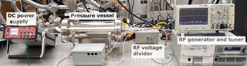
The experimental setup, shown in Fig. 1, consists of two electrodes connected to (RF or DC)
high voltage (HV) inside of a pressure vessel capable of holding pressures up to 10 bar. For each
gas, three breakdown measurements are taken per pressure. When the vessel is at the desired
gas pressure, the RF or DC high voltage is increased until breakdown is observed. For the RF
breakdown measurements, the voltage is monitored through an oscilloscope, described in Sec. 2.3.
When breakdown occurs, the RF circuit goes out of resonance, and the signal on the oscilloscope
collapses. For the DC breakdown measurements, the voltage is monitored on the DC power supply
itself. When DC breakdown occurs, the voltage drops and the current increases above the set
operating current. Any change in the measured DC current from the set value was considered a
voltage breakdown. For both RF and DC, the highest voltage observed before the breakdown is
recorded as the breakdown voltage.
2.1 Gas System
The electrodes are housed inside a five-liter pressure vessel connected to a gas handling and
circulation system. The same gas system was used in previous studies described in Refs. [45, 46],
where further information can be found. The gases used are ultra-high purity (99.999%) grade
helium and argon from AirGas, and xenon from Concorde Specialty Gases. Before each gas fill,
the system is evacuated to better than 10−5 mbar pressure. The xenon is filled through a MonoTorr
PS-4-MT3 hot getter to the maximum pressure and circulated using a MetroCad PumpWorks PW-
2070 pump with flow rates between one and ten liters per minute until the pressure vessel volume
has been circulated through the getter ten times. The process is the same for the helium and argon
gases, except they are filled and circulated through a Saes PureGas MicroTorr HP190-902-FV cold
Figure 1. Photograph of the experimental setup.
–3–Kapton tape
Side View Top View
aluminum
aluminum
Kapton film to HV electrodes
electrodes to HV
to ground
Kapton film
open area
(spark region)
to ground
Figure 2. Diagram of the electrode configuration.
getter instead of the hot getter. HV breakdown measurements are taken at the highest pressure, then
at discrete steps down in pressure as the gas is either vented into a separate evacuated vessel (in
the case of helium and argon) or reclaimed (in the case of xenon). The gas pressure in the vessel
is monitored with an Omega pressure transducer with 10 mbar precision. The measurements were
taken at pressures from 0.1 to 10 bar. The maximum breakdown voltage achievable was 500 V,
discussed in Sec 3, limiting the maximum measurement pressures to 1 bar in xenon and 4 bar in
argon. The minimum pressures measurable in argon and helium are limited by the discrete (1 watt)
step sizes of the RF voltage generator, creating a lower pressure measurement limit of 0.2 bar in
argon and 1 bar in helium.
2.2 Electrode Configuration
The electrodes consist of two aluminum bars positioned in a cross, as shown in Fig. 2. The top bar
is 2.5 in. (64 mm) long by 1.0 in. (25 mm) wide, and the bottom bar is 2.5 in. (64 mm) long by
0.5 in. (13 mm) wide. The cross configuration is used to reduce the amount of electrically stressed
area, which has been shown to affect the breakdown voltage [47]. The top bar is connected to the
HV signal, and the bottom bar is connected to ground. Two pieces of thin, 0.005 in. (0.13 mm)
Kapton film, with 0.0005 in. thickness tolerance, placed 0.4 in. (10 mm) apart, are sandwiched
in between the electrodes to set the gap distance. The voltage breakdown generally happens in the
open area between the electrodes where no Kapton is placed. The position of the breakdown can
be determined from traces left on the electrode surface. The total open (stressed) area between the
electrodes is 0.2 in.2 (130 mm2 ). The entire apparatus is held in place with nylon screws onto a
large (3 in. × 4 in. or 75 mm × 100 mm) piece of HDPE.
2.3 HV Delivery and Monitoring System
The RF HV is supplied by a 13.56 MHz, 300-watt AG Plasma Series generator and an automatic
impedance tuner from T&C Power Conversion. The RF voltage is actively monitored through
a potential divider to an oscilloscope, as shown in Fig. 3. The potential divider consists of a
10 MΩ resistor (labeled Zr ), the oscilloscope probe (labeled Z p ), and the internal impedance
of the oscilloscope itself (labeled Zs ). The impedance of each component at 13.56 MHz is not
–4–T&C
T&C
300 Watt
Automatic
13.56 MHz
Impedance Tuner
RF Generator Zr 10 MΩ
resistor Electrodes
Pressure
Scope vessel
probe Zp
VM
Scope internal Zs
impedance
Oscilloscope +
probe
Figure 3. Diagram of the RF circuit.
420
0.40 Voltage divider factor
Divided voltage [V]
0.35 400
0.30 380
0.25 360
0.20
340
80 100 120 140 80 100 120 140
Measured voltage at electrode [V] Measured voltage at electrode [V]
Figure 4. Example voltage divider measurement. The left plot shows the comparison of the voltage amplitude
measured at the electrode and the voltage amplitude measured after the potential divider on an oscilloscope
with the uncertainty on the voltage measurement. The right plot shows the unitless ratio of the two. The error
bars on the points show the uncertainty on the peak voltages measured by the oscilloscope at the electrode
and after the potential divider. The solid line in the right plot shows the average voltage divider factor, and
the dashed lines show the combined (one standard deviation) uncertainty on the true voltage divider factor,
discussed in Sec 2.4.
precisely known, but the voltage division factor can be measured. We found that the exact voltage
division factor varied with different electrode spacings and impedance tuner settings, presumably
due to changing capacitances and inductances within the circuit impacting the impedance at radio
frequencies. Therefore, it was measured directly for each configuration. Fig. 4 shows an example
measurement of the voltage divider factor for one electrode configuration. The left plot shows
the voltage amplitude measured after the potential divider as a function of the voltage amplitude
measured at the HV electrode, and the right plot shows the voltage divider factor with the total
uncertainty on the conversion to true voltage at the HV electrode, discussed in Sec 2.4. The RF
signal is delivered to the electrodes inside a pressure chamber through a CeramTec copper RF power
feedthrough. The DC HV is supplied by a CAEN DT1471HET desktop HV power supply.
–5–2.4 Estimation of Systematic Uncertainty
The sources of systematic uncertainty that we took into account are the uncertainty in the gas
pressure measurement, the uncertainty in the spacing between the electrodes, and the uncertainty in
the voltage measurement. We also tested the effect on the breakdown voltage due to the electrode
material and the size of the stressed area.
The uncertainty in the gas pressure measurement is 10 mbar and is due to the precision of
the transducer. The uncertainty on the gap distance is due to the compression of the Kapton film
between the electrodes and the flatness of the electrodes. Based on the large elastic modulus of
Kapton and absence of any observable electrode curvature when compared to a granite surface
plate, the uncertainty in the gap distance is estimated to be less than 10%.
The uncertainty in the RF breakdown voltage is due to the measurement of the voltage at
the electrode and to irreducible error from the randomness in the breakdown process itself. The
uncertainty in the RF measurement is estimated from the variance in the voltage division factor,
described in Sec. 2.3, and in the change in the voltage measured at the HV electrode using different,
compensated, oscilloscope probes, which is found to be 5%. To account for the irreducible error
in both the RF and DC breakdown voltages, three measurements were taken consecutively at each
pressure, and the standard deviation of the measured breakdown voltages was added in quadrature to
the uncertainty on the voltage measurement. The gas was not recirculated between the consecutive
measurements at each pressure, but no trend was observed between the breakdown voltage and the
order of the measurements.
3 Results and Discussion
Fig. 5 shows the measured RF and DC breakdown voltages in helium, argon, and xenon with a
0.005 in. gap distance. In the case of both xenon and argon gases, breakdown through the Kapton
spacer ultimately became limiting at a field strength of 40 kV/cm. Before breakdown through the
Kapton became prevalent, inspection of traces on the electrode surfaces showed breakdown was
across the gas gap, rather than along the insulating surface. All gases show the expected Paschen-
like increase of HV strengh with increasing pressure under both RF and DC. The RF breakdown
voltages are found to be systematically lower than the DC ones, an effect which is most significant
in the xenon gas measurements, and represents an approximately 30% effect. The dependence of
the Paschen curve on both P × d and f × d, where f is frequency, was first shown in Refs. [8, 9] and
can be quantified if the electron ionization rate and mobility is well known for the given gas and
pressure [10, 11, 48]. The dependence on frequency decreases with large P × d [11]. This would
explain the larger effect seen in the xenon measurements which are near the Paschen minimum.
When designing this test, we investigated several possible variables that may correlate with
breakdown strength, with results shown in Fig. 6. To determine whether electrode material is
significantly correlated with breakdown strength, the breakdown voltage in argon was measured
with copper as well as aluminum electrodes. The work functions of these metals are sufficiently
different (4.53–5.10 eV for Cu compared to 4.06–4.26 eV for Al [49]) that any substantial dependence
through photoelectron emission would likely be revealed. Fig. 6 shows that there is some systematic
trend, but it is rather small, barely larger than systematic uncertainty. We tested dependence on
–6–Xe DC Xe RF
Ar DC Ar RF
He DC He RF
500
Voltage [Vmax]
400
300
200
100 101 102
Pd [Torr cm]
Figure 5. RF and DC breakdown voltages in xenon, argon, and helium using aluminum electrodes with
a 0.005 in. (0.13 mm) gap. The RF voltage shown is the maximum amplitude of the RF signal with the
total estimated uncertainty. The bands cover the DC breakdown data points including the total estimated
uncertainty. The RF and DC data points were taken at the same pressures.
stressed area using similar electrodes with a larger Kapton insulator resulting in 1/3 of the original
electrode surface available for breakdown. The results of these tests are shown in Fig. 6 lower left.
Again, a small effect is observed, but it appears consistent with the scale of systematic uncertainty.
We also tested Paschen scaling by changing the gap size. We observed that changing the gap
distance and pressure had no significant effect on either the RF of DC breakdown voltages at fixed
P × d, validating Paschen-like behaviour in this regime. These comparisons are shown for both RF
and DC voltages in the right panels of Fig. 6.
3.1 Comparison with Published Data
Fig. 7 shows the comparisons of the DC (left) and RF (right) breakdown voltages in high pressure
argon to a selection of published measurements in low pressure argon in the same P × d range. In
both DC and RF, the measurements fall in the middle of the spread of published data. The behavior
of the comparison between the different electrode materials and stressed areas from Farag et al. in
Fig. 7 left agree well with the behavior shown in Fig. 6 on the lower left.
Fig. 8 shows the comparisons of the DC and RF breakdowns in xenon (left) and helium (right)
to a selection of published data. The previous published data were taken with gap distances in the
range of 6–32 mm for xenon and 0.4–10 mm for helium at sub-atmospheric pressures compared to
ours, taken at a 0.005 in. (0.13 mm) gap distance. The DC breakdown measurements (shaded area)
in xenon agree with published data, and the RF breakdown measurements fall between the published
DC and microwave breakdown measurements. Both the helium RF and DC measurements in Fig. 8
–7–1000 Cu - 0.013 cm (DC) Al - 0.013 cm (DC)
Al - 0.013 cm (DC) Al - 0.026 cm (DC)
800
Voltage [V]
600
400
200 Argon
1000 Cu - SA = 0.4 cm2 (DC) Al - 0.013 cm (RF)
Cu - SA = 1.2 cm2 (DC) Al - 0.026 cm (RF)
800 Al - 0.038 cm (RF)
Voltage [V]
600
400
200
101 102 101 102
Pd [Torr cm] Pd [Torr cm]
Figure 6. Comparison of breakdown voltages in argon using different electrode configurations. The top left
plot shows the (∼8%) effect of using two different electrode materials, the bottom left plot shows the (∼6%)
effect of two different stressed areas, the right plots show the effect of different gap distances with DC on the
top and RF on the bottom.
Raju
Petrovic
Wittenberg
Petrovic
1000 Lisovskiy - 0.65 cm
Lisovskiy - 1.3 cm
Sato - 2 cm
Sato - 4 cm
Farag - Cu, S=19.62cm 0.013 cm - C Lisovskiy - 2.3 cm Sato - 6 cm
Farag - SS, S=19.62cm (this work) Smith - 2 cm 0.013 cm (this work)
Farag - Al, S=19.62cm 0.013 cm - Al 800 Smith - 5 cm 0.026 cm (this work)
Farag - Al, S=38.46cm (this work) Smith - 10 cm 0.038 cm (this work)
Lisovskiy - 0.5 cm 0.026 cm - Al
103 (this work)
DC Voltage [V]
RF Voltage [V]
Lisovskiy - 1.0 cm
Lisovskiy - 2.0 cm 600
Lisovskiy - 4.0 cm
Lisovskiy - 6.0 cm
400
200
Argon Argon
102 100 101 100 101 102
Pd [Torr cm] Pd [Torr cm]
Figure 7. Comparison of DC (left) and RF (right) voltage breakdown in argon gas to a selection of published
data. The RF measurements were all taken at 13.56 MHz, and the maximum voltage amplitude is reported. In
the left plot, the triangles are reported in textbooks [34] and [33], the circles [35] represent different electrode
materials (Cu, Al, and stainless steel) and different stressed areas (19.62 cm and 38.46 cm) with Cu electrodes.
The diamonds were measured in Ref. [36]. The lines are the parameterized curves in Refs. [34, 50]. In the
right plot, the triangles were measured in Ref. [11], the circles in Ref. [37], and the diamonds in Ref. [10].
–8–Petrovic Bhattacharya - 2.15 cm (DC) Petrovic Dezani - 1.0 mm (DC)
Wittenberg Bradford - 3.18 cm (2800 MHz RF) Wittenberg 0.13 mm (DC) (this work)
Jacques - 0.6 cm (DC) 0.013 cm (DC) (this work) Park - 1.0 mm (RF) 0.13 mm (RF)
Jacques - 1.0 cm (DC) 0.013 cm (13.56 MHz RF) Park - 3.3 mm (RF) (this work)
(this work)
103 Jacques - 1.6 cm (DC)
Jacques - 2.0 cm (DC)
103 Park - 9.7 mm (RF)
Moravej - 0.4-2.4 mm (RF)
Voltage [V]
Voltage [V]
102
102
Xenon Helium
100 101 101 102
Pd [Torr cm] Pd [Torr cm]
Figure 8. Comparison of xenon (left) and helium (right) RF and DC voltage breakdown measurements to a
selection of published data. The DC measurements in this work are shown as shaded area in both plots, and
the RF measurements are shown as blue points with error bars for xenon and red points with error bars for
helium. In the left plot, the DC circles [39] were measured using gold electrodes, the DC triangles [38] were
measured using nickel electrodes, and the squares [40] represent microwave breakdown measurements at
2800 MHz. In the right plot, the circles [41] were measured with aluminum electrodes, and the squares [42]
were measured with several gap distances from 0.4–2.4 mm, and the DC triangles [43] were measured using
an aluminum electrode. The lines are the parameterized curves in Refs. [34, 50].
right fall well above the published RF measurements, also taken at 13.56 MHz, and below the the
published DC measurements.
Fig. 9 shows the agreement between our DC and RF breakdown measurements in argon and
xenon and high pressure, large gap-size DC breakdown measurements performed previously by this
group described in Ref. [46]. The previous measurements were taken at similar pressures within
the same gas system, with gap distances of 5 mm.
3.2 Implications for RF Carpets in High Pressure Xenon
The pressure ranges where in-gas breakdowns could be studied were 1 to 10 bar in helium, 0.2
to 4 bar in argon, and 0.1 to 1 bar in xenon. Since RF carpets with small electrode pitches are
commonly printed on a Kapton substrate, our data strongly suggest that the Kapton will be the
limiting factor in their operation in xenon at 10 bar, rather than through-gas breakdowns, as are
limiting in the case of low pressure helium. For a 0.005 in. pitch carpet, the threshold of operation
may thus be close to 500 V peak-to-peak. It is notable, however, that in such a carpet the copper
electrode traces are laid on top of the Kapton and not on either side as in the configuration here.
This implies a smaller electric field through the Kapton itself, and thus our measurements here may
be considered as a cautious lower limit. Future voltage breakdown tests of printed copper electrode
traces on a “flex” Kapton board will determine if this is true.
Comparing this experimental constraint with our simulations, we observe that significant
parameter space remains open where RF carpet operation is theoretically predicted to be possible
in xenon gas at 10 bar. Preliminary simulations have shown that Ba++ ion transport in xenon buffer
gas at 10 bar should be achievable with RF voltages as low as 250 V, given existing electrode pitch
–9–Rogers - Xe DC (5 mm) Rogers - Ar DC (5 mm)
Xe DC (this work) Ar DC (this work)
Xe RF (this work) Ar RF (this work)
104
Voltage [V]
103
102
100 101 102 103
Pd [Torr cm]
Figure 9. Xenon and argon RF and DC voltage breakdown measurements from this work with previous high
pressure xenon and argon DC breakdown measurements with larger gap distance from Ref. [46].
geometries with 0.1 mm gap distances [51].
The next phase of our research program will be to demonstrate ion transport using a 5 cm scale
RF carpet in xenon gas. The results of this test will help establish the viability of RF-carpet based
ion guiding schemes for barium tagging within high pressure xenon gas detectors.
4 Conclusions
We have presented the first RF breakdown strength measurements in xenon gas at pressures above
100 Torr and at frequencies in the MHz range, as well as new measurements of RF and DC
breakdown voltages in argon at pressures of 100 mbar–1 bar and helium at pressures of 1 bar–10 bar
and sub-millimeter gap spacings.
We find that the RF breakdown voltages in high pressure helium, argon, and xenon for sub-
millimeter gap distances agree approximately with existing low pressure data in the same P × d
range with much larger gap distances. In the cases of argon and helium in the P × d region between
10 and 100 Torr cm, the RF and DC breakdown voltages agree well with each other. There are
some deviations between the xenon RF and DC breakdown voltages, but these measurements all
exist below 10 Torr cm, where we start to observe deviations in argon and helium as well. Based on
our data, the limiting factor in the application to high pressure RF carpets in xenon is likely to be
the Kapton substrate that starts to fail at approximately 500 V at 0.005 in. thickness, rather than the
gas itself. This is distinct to the case of helium-based systems, where through-gas breakdowns are
limiting. This warrants future tests of breakdown between electrodes printed on a Kapton substrate.
These results suggest promise for the concept of using RF carpets in high pressure xenon
gas. Such a device may prove to be a critical ingredient in a workable scheme for barium ion
identification within xenon gas time projection chambers.
– 10 –References
[1] HG Dehmelt and FG Major. Orientation of (He 4)+ ions by exchange collisions with cesium atoms.
Physical Review Letters, 8(5):213, 1962.
[2] M Wada, Y Ishida, T Nakamura, Y Yamazaki, T Kambara, H Ohyama, Y Kanai, TM Kojima,
Y Nakai, N Ohshima, et al. Slow RI-beams from projectile fragment separators. Nuclear Instruments
and Methods in Physics Research Section B: Beam Interactions with Materials and Atoms,
204:570–581, 2003.
[3] AE Gehring, M Brodeur, G Bollen, DJ Morrissey, and S Schwarz. Research and development of ion
surfing RF carpets for the cyclotron gas stopper at the NSCL. Nuclear Instruments and Methods in
Physics Research Section B: Beam Interactions with Materials and Atoms, 376:221–224, 2016.
[4] M Ranjan, S Purushothaman, T Dickel, H Geissel, WR Plass, D Schäfer, C Scheidenberger, J Van de
Walle, H Weick, and P Dendooven. New stopping cell capabilities: RF carpet performance at high
gas density and cryogenic operation. Europhysics Letters, 96(5):52001, 2011.
[5] F Arai, Y Ito, I Katayama, P Schury, T Sonoda, M Wada, and H Wollnik. Performance of ion surfing
RF-carpets for high-energy RI beam gas catcher. In Proceedings of the Conference on Advances in
Radioactive Isotope Science (ARIS2014), page 030110, 2015.
[6] S Schwarz. RF ion carpets: The electric field, the effective potential, operational parameters and an
analysis of stability. International Journal of Mass Spectrometry, 299(2-3):71–77, 2011.
[7] F Paschen. Ueber die zum Funkenübergang in Luft, Wasserstoff und Kohlensäure bei verschiedenen
Drucken erforderliche Potentialdifferenz. Annalen der Physik, 273(5):69–96, 1889.
[8] FL Jones and GD Morgan. High-frequency discharges: I Breakdown mechanism and similarity
relationship. Proceedings of the Physical Society. Section B, 64(7):560, 1951.
[9] WG Townsend and GC Williams. The electrical breakdown of gases in uniform high frequency fields
at low pressure. Proceedings of the Physical Society, 72(5):823, 1958.
[10] M Sato and M Shoji. Breakdown characteristics of RF argon capacitive discharge. Japanese Journal
of Applied Physics, 36(9R):5729, 1997.
[11] VA Lisovskiy and VD Yegorenkov. RF breakdown of low-pressure gas and a novel method for
determination of electron-drift velocities in gases. Journal of Physics D: Applied Physics,
31(23):3349, 1998.
[12] M Fukugita and T Yanagida. Baryogenesis without grand unification. Physics Letters B, 174:45, 1986.
[13] MK Moe. Detection of neutrinoless double-beta decay. Physical Review C, 44(3):R931, 1991.
[14] D Sinclair, E Rollin, J Smith, A Mommers, N Ackeran, B Aharmin, M Auger, PS Barbeau,
C Benitez-Medina, M Breidenbach, et al. Prospects for Barium tagging in gaseous xenon. Journal of
Physics: Conference Series, 309(1):012005, 2011.
[15] T Brunner, D Fudenberg, A Sabourov, VL Varentsov, G Gratta, D Sinclair, and EXO collaboration. A
setup for Ba-ion extraction from high pressure Xe gas for double-beta decay studies with EXO.
Nuclear Instruments and Methods in Physics Research Section B: Beam Interactions with Materials
and Atoms, 317:473–475, 2013.
[16] K Twelker, S Kravitz, M Montero Díez, G Gratta, W Fairbank Jr, JB Albert, DJ Auty, PS Barbeau,
D Beck, C Benitez-Medina, et al. An apparatus to manipulate and identify individual Ba ions from
bulk liquid Xe. Review of Scientific Instruments, 85(9):095114, 2014.
– 11 –[17] B Mong, S Cook, T Walton, C Chambers, A Craycraft, C Benitez-Medina, K Hall, W Fairbank Jr,
JB Albert, DJ Auty, et al. Spectroscopy of Ba and Ba+ deposits in solid xenon for barium tagging in
nEXO. Physical Review A, 91(2):022505, 2015.
[18] T Brunner, D Fudenberg, V Varentsov, A Sabourov, G Gratta, J Dilling, R DeVoe, D Sinclair,
W Fairbank Jr, JB Albert, et al. An RF-only ion-funnel for extraction from high-pressure gases.
International Journal of Mass Spectrometry, 379:110–120, 2015.
[19] DR Nygren. Detection of the barium daughter in 136Xe-> 136Ba+ 2e- by in situ single-molecule
fluorescence imaging. Nuclear Instruments and Methods in Physics Research Section A:
Accelerators, Spectrometers, Detectors and Associated Equipment, 824:2–5, 2016.
[20] BJP Jones, AD McDonald, and DR Nygren. Single molecule fluorescence imaging as a technique for
barium tagging in neutrinoless double beta decay. Journal of Instrumentation, 11(12):P12011, 2016.
[21] N Byrnes, FW Foss Jr, BJP Jones, AD McDonald, DR Nygren, P Thapa, A Trinidad, and NEXT
collaboration. Progress toward barium tagging in high pressure xenon gas with single molecule
fluorescence imaging. In Journal of Physics: Conference Series, volume 1312, page 012001. IOP
Publishing, 2019.
[22] AD McDonald, BJP Jones, DR Nygren, C Adams, V Álvarez, CDR Azevedo,
JM Benlloch-Rodríguez, FIGM Borges, A Botas, S Cárcel, et al. Demonstration of single-barium-ion
sensitivity for neutrinoless double-beta decay using single-molecule fluorescence imaging. Physical
Review Letters, 120(13):132504, 2018.
[23] C Chambers, T Walton, D Fairbank, A Craycraft, DR Yahne, J Todd, A Iverson, W Fairbank,
A Alamare, JB Albert, et al. Imaging individual barium atoms in solid xenon for barium tagging in
nEXO. Nature, 569:203–207, 2018.
[24] P Thapa, I Arnquist, N Byrnes, AA Denisenko, FW Foss, BJP Jones, AD McDonald, DR Nygren, and
K Woodruff. Barium chemosensors with dry-phase fluorescence for neutrinoless double beta decay.
Scientific Reports, 9(1):1–13, 2019.
[25] NK Byrnes, AA Denisenko, FW Foss Jr., BJP Jones, AD McDonald, DR Nygren, P Thapa,
K Woodruff, and NEXT collaboration. Barium tagging with selective, dry-functional, single molecule
sensitive on-off fluorophores for the NEXT experiment. In Meeting of the Division of Particles and
Fields of the American Physical Society, Northeastern University, Boston,, 2019.
[26] I Rivilla, B Aparicio, JM Bueno, D Casanova, C Tonnelé, Z Freixa, P Herrero, JI Miranda,
RM Martínez-Ojeda, F Monrabal, et al. Towards a background-free neutrinoless double beta decay
experiment based on a fluorescent bicolor sensor. arXiv preprint, 2019.
[27] J Martín-Albo, JM Vidal, P Ferrario, M Nebot-Guinot, JJ Gómez-Cadenas, V Álvarez, CDR
Azevedo, FIG Borges, S Cárcel, JV Carrión, et al. Sensitivity of NEXT-100 to neutrinoless double
beta decay. Journal of High Energy Physics, 2016(5):159, 2016.
[28] E Bainglass, BJP Jones, FW Foss Jr, MN Huda, and DR Nygren. Mobility and clustering of barium
ions and dications in high-pressure xenon gas. Physical Review A, 97(6):062509, 2018.
[29] P Novella, B Palmeiro, A Simón, M Sorel, C Adams, P Ferrario, G Martínez-Lema, F Monrabal,
Grzegorz Zuzel, JJ Gómez-Cadenas, et al. Measurement of radon-induced backgrounds in the NEXT
double beta decay experiment. Journal of High Energy Physics, 2018(10):112, 2018.
[30] K Woodruff. Barium ion transport in high pressure xenon gas using RF carpets. Presented at the 13th
International Conference on Stopping and Manipulation of Ions, McGill University, July 2019.
– 12 –[31] OB Postel and MA Cappelli. Vacuum emission and breakdown characteristics of a planar He–Xe
microdischarge. Applied Physics Letters, 76(5):544–546, 2000.
[32] Y Sosov and CE Theodosiou. Determination of electric field-dependent effective secondary emission
coefficients for He/Xe ions on brass. Journal of applied physics, 95(8):4385–4388, 2004.
[33] M Hirsh. Gaseous electronics, volume 1. Elsevier, 2012.
[34] MA Lieberman and AJ Lichtenberg. Principles of plasma discharges and materials processing. John
Wiley & Sons, 2005.
[35] OF Farag, MM Mansour, NM El-Sayed, and MH Elghazaly. Mixing and cathode material effects on
breakdown voltage of DC Ar glow discharge. Advances in Applied Science Research, 4(1):146–150,
2013.
[36] VA Lisovskiy, SD Yakovin, and VD Yegorenkov. Low-pressure gas breakdown in uniform DC
electric field. Journal of Physics D: Applied Physics, 33(21):2722, 2000.
[37] HB Smith, C Charles, and RW Boswell. Breakdown behavior in radio-frequency argon discharges.
Physics of Plasmas, 10(3):875–881, 2003.
[38] AK Bhattacharya. Measurement of breakdown potentials and Townsend ionization coefficients for the
Penning mixtures of neon and xenon. Physical Review A, 13(3):1219, 1976.
[39] L Jacques, W Bruynooghe, R Boucique, and W Wieme. Experimental determination of the primary
and secondary ionisation coefficients in krypton and xenon. Journal of Physics D: Applied Physics,
19(9):1731, 1986.
[40] HM Bradford, DM Fraser, GFO Langstroth, and AD MacDonald. Electrical breakdown in xenon and
krypton at ultrahigh frequencies. Canadian Journal of Physics, 37(10):1166–1170, 1959.
[41] J Park, I Henins, HW Herrmann, and GS Selwyn. Gas breakdown in an atmospheric pressure
radio-frequency capacitive plasma source. Journal of Applied Physics, 89(1):15–19, 2001.
[42] M Moravej, X Yang, GR Nowling, JP Chang, RF Hicks, and SE Babayan. Physics of high-pressure
helium and argon radio-frequency plasmas. Journal of Applied Physics, 96(12):7011–7017, 2004.
[43] V Borg Dezani and JL Ginoux. Investigation of breakdown voltage curves for pure helium and
silane–helium mixtures. Physics of plasmas, 1(4):1060–1063, 1994.
[44] GK Pang. Development of radiofrequency carpets for ion transport at the NSCL. Doctoral
dissertation, Michigan State University, 2011.
[45] AD McDonald, K Woodruff, B Al Atoum, D González-Díaz, BJP Jones, C Adams, V Álvarez,
L Arazi, IJ Arnquist, CDR Azevedo, et al. Electron drift and longitudinal diffusion in high pressure
xenon-helium gas mixtures. Journal of Instrumentation, 14(08):P08009, 2019.
[46] L Rogers, RA Clark, BJP Jones, AD McDonald, DR Nygren, F Psihas, C Adams, V Álvarez, L Arazi,
CDR Azevedo, et al. High voltage insulation and gas absorption of polymers in high pressure argon
and xenon gases. Journal of Instrumentation, 13(10):P10002, 2018.
[47] M Okawa, T Shioiri, H Okubo, and S Yanabu. Area effect on electric breakdown of copper and
stainless steel electrodes in vacuum. IEEE Transactions on Electrical Insulation, 23(1):77–81, 1988.
[48] T Kihara. The mathematical theory of electrical discharges in gases. Reviews of Modern Physics,
24(1):45, 1952.
[49] Josef Hölzl, Franz K Schulte, and Heribert Wagner. Solid surface physics, volume 85. Springer, 2006.
[50] HH Wittenberg. Gas tube design. Electron Tube Design, 792, 1962.
– 13 –[51] Alec Hamaker, M Brodeur, JM Kelly, J Long, C Nicoloff, S Ryan, BE Schultz, P Schury, and
M Wada. Experimental investigation of the repelling force from RF carpets. International Journal of
Mass Spectrometry, 404:14–19, 2016.
– 14 –You can also read