Real time defect detection during composite layup via Tactile Shape Sensing - De Gruyter
←
→
Page content transcription
If your browser does not render page correctly, please read the page content below
Sci Eng Compos Mater 2021; 28:1–10

Research Article

Michael Elkington*, Even Almas, Ben Ward-Cherrier, Nick Pestell, J. Lloyd, Carwyn Ward, and
Nathan Lepora

Real time defect detection during composite layup
via Tactile Shape Sensing
https://doi.org/10.1515/secm-2021-0001                                Composite products have traditionally been manufac-
Received Jun 28, 2019; accepted Dec 10, 2019                     tured by hand, with skilled workers placing and compact-
                                                                 ing layers of fibres onto moulds to make high performance,
Abstract: In this study an automated composite layup end
                                                                 small production volume products. There has been a recent
effector is presented which is the first to be able to find
                                                                 expansion of composites use into high volume industries
defects in real time during layup using tactile shape sens-
                                                                 such as civilian aerospace and mass-produced cars. Man-
ing. Based around an existing sensor concept developed
                                                                 ual production cannot keep up with increased demands
by the Bristol Robot Laboratory known as the ‘TacTip’, a
                                                                 and as a result a wide variety of automated solutions have
new end effector is developed, replacing the soft gel core
                                                                 been developed [2, 3]. Despite this, hand layup remains a
of the original sensor was replaced by a much firmer elas-
                                                                 crucial part of the composites industry, primarily due to its
tomer, enabling it to apply up to 400N of compaction force.
                                                                 ability to layup composite material onto the most complex,
In this paper it is shown to successfully detect typical de-
                                                                 highly curved moulds which automated processes cannot
fects such as wrinkles, foreign objects, layup errors or in-
                                                                 successfully tackle. Research into what enables hand layup
correct material types while simultaneously compacting
                                                                 to stay ahead in this field was conducted by the author in a
preimpregnated composite materials over complex mould
                                                                 previous study [4]. It was concluded that one of the main
shapes.
                                                                 advantages of manual layup was the ability of the human
Keywords: Prepreg, Carbon Fibre, Wrinkle, Bridge, Foreign workers to gather real time feedback from their work via
Object, TacTip                                                   both visual and tactile sensing to ensure the products are
                                                                 defects free. This allows them to constantly adjust their
                                                                 actions in a closed-loop feedback system, correcting any
                                                                 defects or unwanted features as soon as they begin to arise.
1 Introduction
                                                                      In contrast most automated processes only gather feed-
                                                                 back once the layup has been completed. This is often still
Composite materials generally consist of thousands of car-
                                                                 completed manually, sequentially inspecting each ply af-
bon or glass fibres which individually have excellent spe-
                                                                 ter it has been laid up, leading to up to 4-6 hours of dead
cific structural properties. These are typically arranged into
                                                                 time during manufacture of large high-performance parts
sheets or tapes of aligned fibres which need to be formed
                                                                 according to Krombholz et al. [5]. Because the inspection
into the shape of the finished components. In order to make
                                                                 process can add a significant delay to the manufacturing
the most of these properties in structural applications the
                                                                 time there has been a drive to automate the inspection pro-
fibres need to be strongly bonded together and remain as
                                                                 cesses. The ideal situation would be for the inspection to
straight and aligned as possible in the finished product.
                                                                 run in parallel to the layup process rather than in a stop-
Defects such as wrinkles, bridges across concave corners,
                                                                 start sequential manner. As well as reducing downtime,
foreign objects or misplaced plies can severely compromise
                                                                 this could facilitate some level of closed-loop feedback in
the integrity of the material [1].
                                                                 the automated process.
                                                                      Automated quality assurance has typically been lim-
                                                                 ited to vision-based systems such as Aligned Vision’s ‘Laser
                                                                 VisionTM ’ system, which is being commercially used to de-
*Corresponding Author: Michael Elkington: University of Bristol
                                                                 tect misplaced plies, gaps and fibre angles during auto-
Bristol, United Kingdom of Great Britain and Northern Ireland;
Email: michael.elkington@bristol.ac.uk                           mated tape laying [6]. A prototype system has also been
Even Almas, Ben Ward-Cherrier, Nick Pestell, J. Lloyd, Carwyn    developed which uses laser parallax to gauge the surface
Ward, Nathan Lepora: University of Bristol Bristol, United King- profile of the composite material in order to detect wrinkles,
dom of Great Britain and Northern Ireland

  Open Access. © 2021 M. Elkington et al., published by De Gruyter.       This work is licensed under the Creative Commons Attribution
4.0 License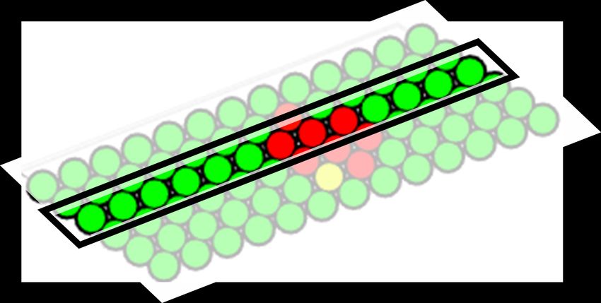
2 | M. Elkington et al.

bridging and foreign objects. Airbus has proposed a sim-                case of defects occurring during composites layup, the vast
ilar system which uses a projected laser line and camera                majority will manifest as a 3D shape, such as a wrinkle, a
mounted directly behind an Automated Fibre Placement                    bridge across a concave corner or a foreign object trapped in
(AFP) head to scan tapes of composite material laid onto                the layup [1]. It could be argued that an out-of-plane defect
a tool, but only minimal details have been published [7].               such as a wrinkle may also effect the contact pattern or total
Three-dimensional laser scanning equipment which could                  force applied by an end effector. A project to give composite
map a surface is also commercially available but can be pro-            end effectors tactile force feedback has been undertaken
hibitively expensive [8]. Tactile sensing however remains a             by Airbus [17] citing motivations of ‘anticipating and/or
relatively untouched area for automated systems.                        preventing laying errors’ as well using the data for longer
                                                                        term optimisation of the process. They present a concept
                                                                        for an AFP or Automated Tape Laying (ATL) roller equipped
                                                                        with pressure sensing piezo-electric transducers to give real
2 Tactile sensing                                                       time feedback. No actual performance data or examples
                                                                        are available at present. Alternatively compaction force has
The importance of tactile sensing in robotics has been cited
                                                                        been used previously to inspect composite materials, using
by many other studies [9] and it has been a goal for over
                                                                        the data to infer the through-thickness permeability dry
30 years to enable the detection of properties that are dif-
                                                                        fibre preforms [18]. A promising option that can analyse
ficult to detect via vision alone, such as contact force or
                                                                        three dimensional shape rather than force has been devel-
3D shape [10]. For example robotics researchers have used
                                                                        oped at Bristol Robotics Laboratory (BRL) [19]. This optical
tactile force sensing to try and replicate the feeling in a
                                                                        tactile sensor known as the ‘TacTip’ has been shown to
finger, often for use in prosthetic limbs to give the user
                                                                        be capable of analysing a wide range three-dimensional
more feedback to make the use of the hand more intu-
                                                                        shapes in real time and was identified as having potential
itive [11]. The generic term ‘Tactile sensing’ actually covers
                                                                        to operate in a composite layup environment [20].
a range of properties which are typically measured during
contact with an object. As outlined by Nichollas et al. [12]
these include contact detection, force measurement, three-
dimensional shape, slip or temperature. Multiple reviews                3 The TacTip
on tactile sensing are available covering a wide range of
different sensor types [13, 14]. It could be argued that all of         The TacTip is an optical tactile sensor, capable of analysing
these properties have some importance during the layup of               the three-dimensional shape of a surface. A schematic dia-
composite materials. The thermosets resins typically used               gram of a sensor is shown in Figure 1. The TacTip assembly
in advanced composites are thermo-visco-elastic, hence                  is typically mounted onto a six-axis robotic arm which can
temperature, applied force and contact time will all in-                precisely and repeatedly position the sensor. In operation
fluence the behaviour of the material. In this study the                the TacTip is lowered onto a surface to typically 6mm deflec-
focus will be on detecting defects that manifest as three-              tion and then raised again, an action which will be referred
dimensional shapes.                                                     to as a ‘Tap’ from here on. The only electronic components
     There are a wide range of devices that can detect pres-            in the sensor are a ring of LED lights and a Microsoft Cinema
sure or force, but crucially cannot detect three-dimensional            HD webcam. The lower part of the sensor which deforms
shape. Many of these use pressure sensitive films [15, 16], or          around a surface profile during a tap is a hemispherical
pressure sensors embedded into a rubber matrix [10]. In the             membrane filled with a clear gel. On the inner surface ‘pins’

Figure 1: (Left) Schematic of the TacTip construction, (Right) Image of the TacTip tapping down onto a prepreg ply with wrinkle.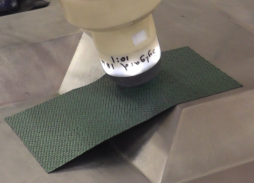
Real time defect detection during composite layup via Tactile Shape Sensing    | 3

    No Contact                                  Contact on flat surface                      Contact on surface with ridge

Figure 2: Images from the camera inside the TacTip in three states: (Left) Standard non-contact configuration, (Middle) Contacting a flat
surface, (Right) Contacting a surface with a ridge.

which protrude perpendicularly to the surface of the mem-
brane into the gel core. The tip of each pin is painted white
                                                                4 Sensor design
to act as an optical marker, contrasting against the black
                                                                The sensor design chosen for the basis of this project was
membrane material. As the hemisphere deforms around
                                                                similar to that used in a range of other studies, featuring a
a shape, the pins move and rotate relative to their origi-
                                                                40 mm diameter hemispherical skin, which is 1mm thick
nal position. Lit by the ring of LEDs, the movement of the
                                                                with 127 pins on the inner surface. The current materials in
white pins tips is recorded by the inbuilt camera, exam-
                                                                use are a rubberlike silicone (TangoBlack plus (FLX980)) for
ples of which are shown in Figure 2. The camera footage
                                                                the skin, shore hardness (A) 30, and silicone gel (RTV27906)
is then processed in real time using OpenCV for Python to
                                                                as the medium. The original versions of the TacTip were
output the position of every pin in terms of X and Y pixel
                                                                designed solely as a sensor and the gel filled tip is only
locations in each frame. This data is then passed onto MAT-
                                                                capable of applying 10N or an average pressure of approx-
LAB for further analysis which is outlined separately in
                                                                imately 0.06MPa, just over half atmospheric pressure. To
section 6. The spatial resolution available from the sensor
                                                                enable effective compaction of composite plies, especially
is much smaller than the spacing of pins might suggest,
                                                                into and around tight corners, this force needed to be dra-
with the sensors capable of ‘super-resolution’, creating a
                                                                matically increased. A range of approaches to making a
sub millimetre sensitivity [21]. In a previous study by the au-
                                                                ‘hard’ TacTip such as thicker membranes or alternative ma-
thor the standard form of the TacTip has been proven to be
                                                                terials were tested in a master’s project by Almas [23]. The
able to detect a range of composite manufacturing defects
                                                                most successful of these designs changed the Gel medium
including wrinkles, foreign objects and bridged concave
                                                                for a Polydimethylsiloxane (PDMS) elastomer (Sylgard184,
corners [20]. In that work it was acting purely as a sensor,
                                                                manufactured by Dow Chemicals [24]). The new harder
and the aim of this new study is to develop a version that
                                                                sensor was demonstrated as capable of applying enough
can apply significant compaction forces at the same time
                                                                pressure to consolidate prepreg onto a mould such that it
as tactile shape sensing to create a functional layup end
                                                                could be then cured into a finished laminate. To quantify
effector.
                                                                the applied force, a compression test of an elastomer filled
                                                                TacTip against a flat surface has been completed and the
                                                                results are presented in Figure 3. It shows the TacTip is now
                                                                able to apply over 400N of force, generating an average con-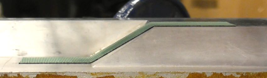
4 | M. Elkington et al.
tact pressure of approximately 2.26 MPa, an approximately of known stimuli and recording the responses prior to it
40-fold increase compared to the original TacTip. being applied. When the TacTip is being applied as a sen-
As a sensor, the hard elastomer filled TacTip was shown sor (referred to as ‘Testing’ from here on) the incoming X/Y
in the previous study to retain the basic functionality of coordinates are compared with those from the pre-recorded
the original sensor by differentiating between basic shapes library of data collected during the training. If the tap is sig-
such as flat surfaces or small three-dimensional features. nificantly alike to any of the training taps for that location,
This new study aims to prove the harder TacTip is sensitive then a match is identified, and the shape of the test surface
enough to detect a range of real composite layup defects. can therefore be inferred. For the training to work effec-
tively in many of the previous application of the TacTip the
‘training’ data has consisted of a large number of repeats.
For the specific application of composite layup the data
has to be collected during the layup a process rather than
just repeatedly tapping onto a static object. This makes col-
lecting such large volumes of training data very costly and
ideally it should be avoided. In this study we set a target
of maximum three repeats for each tap to fully train the
system. This limited some of the techniques that could be
applied such as neural networks or other machine learning
tools which have been used in previous studies.
Figure 3: Force displacement graph showing how the Elastomer core
TacTip can apply up to 400N at its typical displacement depth of 5.1 Anomaly detection
6mm.
The detection of defects during the manufacturing process
can be broken down to an anomaly detection problem,
where it is possible to train on a ‘correct’ layup, and the
task of the TacTip is to detect if test layups differ in any way,
5 Data collection and analysis which would suggest a defect has occurred. A wide-ranging
review of techniques for anomaly detection is presented by
The data output from the TacTip is the X and Y coordinates Chandola et al. [26] and it was concluded that given the lim-
of each of the 127 pins. While there have been recent efforts ited training opportunities, that the best approach would
to directly calculate the deformed shape of the hemisphere be to directly compare the location of the pins in testing and
from the pin positions [25], the most successful applica- train data, utilising a ‘nearest neighbour approach’. Two
tions of the TacTip have used a different approach. This is taps are compared by selecting the position of each pin in
based around ‘training’ the TacTip by exposing it to range one tap and calculating the linear distance to the position
of the same pin in the other tap, as shown schematically in
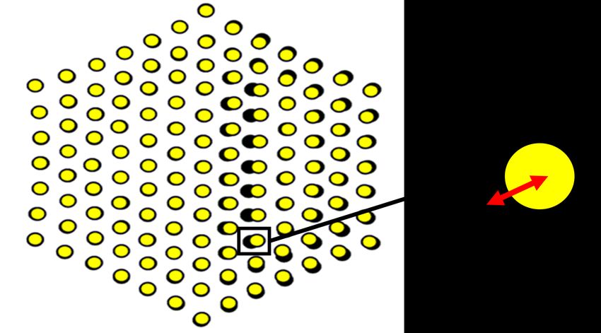
Figure 4: (Left) Schematic of how difference in pin location between taps is used to detect anomalies. Here the Black dots show the TacTip
response to a correct flat surface while the yellow dots show the response to an anomalous contoured surface. (Right) Schematic Diagram
of the ‘Nearest Neighbour’ Technique, in this case the test tap (Black) was closest to the third of the training taps.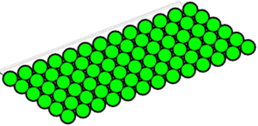
Real time defect detection during composite layup via Tactile Shape Sensing     | 5

Figure 5: (Left) Image of the TacTip being applied to a layup while (Right) Real time data is displayed to the user via a Matlab scatter plot.
Green = Correct, Red = Defect found.

Figure 4. The overall ‘score’ for each tap is the average pin number of pins, all of which are located around a small
training-testing position difference across all the pins. The localised defect, would the sensor fail to function correctly.
‘nearest neighbour’ approach is applied when comparing a
single ‘test’ tap to the three ‘training’ taps from the same
location. For every pin within the test tap, the distance to
that particular pin in each of the three training taps is cal-
                                                               6 Testing methodology
culated, but only the smallest of the three distances is input
                                                               The robotic arm was programmed to tap the TacTip onto the
in the final tap ‘score’, as shown schematically in Figure 4.
                                                               sample layups in a Rasta-scan pattern such that the entire
This approach can reduce the impact of any erroneous train-
                                                               ply was compacted onto the mould. The TacTip was trained
ing data. A data analysis program was written in MATLAB,
                                                               by scanning three ‘correct’ layups and during the testing
capable of processing training and testing data in real time
                                                               phase the exact same tap patterns were repeated on five
on a standard laptop. An image of the TacTip being applied
                                                               examples of each test scenario. The TacTip was trained and
while real time data is displayed on the MATLAB user in-
                                                               tested across a range of composite layup and the results are
terface is shown in Figure 5 with a green to red colourmap
                                                               presented in section 8. For every tap the TacTip was raised
showing the acceptance level for the tap.
                                                               and lowered at 80mms−1 and paused for 0.2s at the lowest
                                                               point of each tap to allow collection of a few video frames of
                                                               the TacTip in a steady state. Each dot in the plotted results
5.2 Fault tolerance
                                                               corresponds to a tap of the TacTip. All the figures shown in
                                                               Tables 1–3 were generated in real time as the TacTip was
Fault tolerance is a key characteristic for a successful sen-
                                                               applied to prepreg material, and are all plotted on the same
sor, such that it can continue to operate even if some ele-
                                                               Colour axis and colour map in MATLAB, with the exception
ments of the sensors should fail [14]. The standard TacTip
                                                               of the AFP tow overlap and gap trials in Table 3 which use
uses a robust and proven pin tracking algorithm but the
                                                               a narrower limit to highlight very subtle defects.
analysis software has been developed such that in the un-
likely case of one or more pins being temporarily lost during
tracking or becoming damaged, it can still function. This is
achieved in the software by selectively removing the data 7 Results
for pins which are missing in either the test or training
data, or which show a displacement much greater than 7.1 Flat Panel layup
the surrounding pins, suggesting an error. This creates a
sensor that rather than completely failing as more pins are The first round of the tests was on a flat rectangular layup.
removed, would just gradually reduce in sensitivity. With Five ‘correct’ versions of the flat layup were placed in the
a total of 127 pins in the head, removing up to around five correct location and then compacted and scanned by the
pins will only have a very small detrimental effect of the TacTip, with the outer taps going beyond the edge of the ply.
performance in most sensing applications. Only in the very All five versions produced 100% matches to the training
unlikely event of having to remove a significantly greater data. Further layups containing a wrinkle, plies or films
                                                               placed below the surface or incorrect positioning or ma-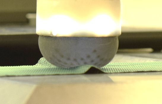
6 | M. Elkington et al.

Table 1: Results from Trialling the TacTip on a range of Flat layups.

1A – Correct ply

1B – Wrinkled ply

1C – Small square of
prepreg beneath the layup

1D – Small square of back-
ing film beneath the layup

1E – Ply misplaced by 3mm
down and left

1F – Incorrect ply: Different
material thickness

     Good Match: Passed                       Medium match: Possible Defect                        Poor Match: Failed

terial type were all trialled using the same method. In all             7.2 Complex layup
cases where there was a defect it is was identified by the Tac-
Tip. Examples of the results are shown in Table 1 alongside             The TacTip was also trialled on a layup featuring convex
schematics of the defective plies.                                      and concave corners with sharp almost 0mm radii. The end
                                                                        effector could compact the woven prepreg onto the mould
                                                                        without any bridging or defects as shown in Figure 6. Two
Real time defect detection during composite layup via Tactile Shape Sensing   | 7

Table 2: Results of TacTip scans on the Complex curved layup

Correct ply

Bridged ply

Extra strip of Ply under the
surface

     Good Match: Passed                    Medium match: Possible Defect                              Poor Match: Failed

defective versions of the layup were scanned, one featuring 7.3 Automated Fibre Placement
a strip of prepreg placed below the layup and another with
a filler placed in the concave corner to simulate a bridge. In AFP, one of the most common defects is dropped tows,
As shown in Table 2, the TacTip successfully detected these where one of the tows breaks or stops being laid down [27].
defects during the layup of the ply.                        The TacTip was trained on a layup of Uni-directional
                                                            6.35mm (1/4”) tapes as used in AFP. In the test layup the
                                                            last third of one of the tapes was removed to simulate a
                                                            dropped tow and this was successfully detected by the sen-
                                                            sor. Another common defect is gaps or overlaps between the
                                                            tows. A gap and an overlap of 3.18mm (1/8”) were created
                                                            manually and were successfully detected by the sensor.

Figure 6: Image of a ply successfully laid onto a curved mould shape
by the TacTip.                                                         7.4 Repeatability

                                                                       Every trial presented in section 8 was repeated five times
                                                                       with excellent repeatability. Figure 7 shows a selection of
8 | M. Elkington et al.
Table 3: Results of TacTip scans on a simulated AFP layup.
Correct AFP layup
AFP layup with a missing
section of tow
Gap between tows 3.18mm
(1/8”)
*Narrower colour axis limits
used to highlight results
Overlap between courses
3.18mm (1/8”)
*Narrower colour axis limits
used to highlight results
Good Match: Passed Good Match: Passed Good Match: Passed
Figure 7: (Left) Selection of tap data presented with error bars showing the standard deviation across five samples. (Right) Illustration
showing location of these selected taps, for the full plot see Table 1.
data from one of the flat panel tests in bar graph format.
The error bars represent one standard deviation from the
8 Conclusions and Future work.
five repeats at this trial. Of the 3630 Taps completed during
A new version of the ‘TacTip’ tactile shape sensor featuring
the repeats of the results shown in section 8, there was only
an elastomer core rather than the original soft gel core has
a single tap which gave a single false defect decision.
been shown to be capable of detecting a range of composite
defects while simultaneously compacting prepreg material
onto a mould surface. It successfully detected wrinkles,
bridges and a range of foreign objects including thing filmsReal time defect detection during composite layup via Tactile Shape Sensing | 9
placed below the ply. The new elastomer core increased the ber of adjacent or aligning taps all show a low level defect,
force that can be applied from under 10N to over 400N. The this data could be flagged as a potential error.
detection was all completed in real time using a standard The current version operates only as an anomaly de-
laptop PC running Python and MATLAB. This successful tection system and does not attempt to classify the ‘type’
study has shown that tactile shape sensing with TacTip of defect. The TacTip and other tactile sensors has been
technology could be a genuine option for quality control in demonstrated in multiple other studies as being able to
future automated systems. differentiate between different object types [32, 33]. There
is potential therefore to build a version that could classify
whether a defect is wrinkle, misplaced ply or other type of
defect. This data would be useful for informing the result-
9 Future work ing decision about how to correct the defect. TacTip data
has been used to adjust position of an object in a grasp [34]
9.1 Hardware optimisation or to the follow the edge of an unknown shape [34] showing
the potential for real time use of the data to inform later
Despite substituting the Gel core for an Elastomer the Tac- automated actions. Information about the defect could be
Tip has retained sufficient tactile shape sensing capability used to adjust parameters like the speed, temperature or
to detect the defects during layup. However the sensitivity force. The next step would be using the information to in-
of the elastomer sensor is lower than that of the original gel form automated corrective actions similar to how humans
based sensor but there is further scope to fine tune the hard- operate in hand layup.
ness of the elastomer by adjusting the hardness/mixer ratio
or changing material entirely to tune the balance between Acknowledgement: The authors gratefully acknowledge
application force and sensitivity [28]. the support of the EPSRC through the EPSRC Future Com-
In addition to adjusting the hardness, the shape of the posites Manufacturing Research Hub (Grant: EP/P006701/1)
sensor can be optimised. The new Elastomer filled version and the Leverhulme Trust Research Leadership Award on
of the TacTip presented in this study uses the same shape ’A biomimetic forebrain for robot touch’ (RL-2016-039). The
as the existing versions which have been designed to op- Authors would also like to thank Andy Stinchcombe at the
erate on a wide range of tactile shape sensing tasks but it Bristol Robotics Laboratory for his help throughout the
may not be optimal for layup tasks. The TacTip technology project.
could be translated into different shapes like those used
in composite layup technologies such as that developed
by Elkington et al. [29] or Bjornson et al. [30]. A cylindrical
version of the TacTip has been successfully demonstrated, References
designed for medical use in detecting tumours on the inside
of the Gastrointestinal gland [31]. This has the potential to [1] Potter K.D., “Understanding the origins of defects and variabil-
ity in composites manufacture.” In International Conference on
form the basis for a sensor that can roll across a surface
Composite Materials (ICCM)-17, Edinburgh, UK., 2009.
rather than probe, like those used in automated processes [2] Land P., Crossley R., Branso, D. and Ratchev S., 2015. “Technol-
such as AFP or ATL. ogy Review of Thermal Forming Techniques for use in Composite
Component Manufacture.” SAE International Journal of Materials
and Manufacturing, 9, 81-89.
[3] Elkington M., Ward C., & Sarkytbayev A., Automated composite
9.2 Analysis optimisation
draping: a review. In SAMPE 2017, Orlnado, Florida, USA, Decem-
ber 11th-14th 2017, SAMPE North America.
The difficulties in collecting a large set of a training data lim- [4] Elkington M., Bloom D., Ward C., Chatzimichali A.P. and Potter
its the data processing approaches that can be applied to K.D., 2013, July. Understanding the lamination process. In 19th
this anomaly detection problem. However, the current ver- Int. Conf. on Composite materials, Montreal, Canada, July 28th -
sion uses a very stripped down but effective and efficient Aug 2nd , 2013, 4385-4396.
[5] Krombholz C., Delisle D. and Perner M., 2013. “Advanced auto-
processing system which could be built upon in further
mated fibre placement.” Advances in Manufacturing Technology
studies, adding in rigorous statistical analysis. For exam- XXVII, 411-416.
ple, the current approach only considers each tap result [6] Blake S. Whittington D., Potter KD., Elkington M., Crowley D.,
in isolation and does not consider the spatial relationship “Real time gauging of wrinkle shear and ridge formation in an
between the taps. For example an isolated tap with a small automated composite manufacturing process”, The Composites
and Advanced Materials Expo, Anaheim Convention Center, Ana-
difference might be ignored, however if a significant num-10 | M. Elkington et al.
heim, California, USA, Sep 26-29, 2016. [21] Lepora, N.F. and Ward-Cherrier, B., 2015, September. Superres-
[7] Weimer C, Friedberger A, Helwig A, Heckner S, Buchmann C, olution with an optical tactile sensor. In 2015 IEEE/RSJ Interna-
Engel F. Increasing the productivity of CFRP production processes tional Conference on Intelligent Robots and Systems (IROS) ,
by robustness and reliability enhancement, The Composites and 2686-2691.
advanced materials Expo, Anaheim, California, USA, September [22] Lepora, NF, Church, A, De Kerckhove, C, Hadsell, R & Lloyd,
27-29, 2016. J, 2019, ‘From Pixels to Percepts: Highly Robust Edge Percep-
[8] Creaform, “GO!SCAN 20TM Technical Specification”, 2016, tion and Contour Following Using Deep Learning and an Optical
Online article, Available from: (http://www.creaform3d.com/en/ Biomimetic Tactile Sensor’. IEEE Robotics and Automation Let-
metrology-solutions/handheld-portable-3d-scanner-goscan- ters, 4, 2101-2107
3d#section-1), Accessed 11/01/2019. [23] E. Almas, Developing Composite layup end-effectors with tactile
[9] Cutkosky, M.R., Howe, R.D. and Provancher, W.R., 2008. “Force sensing capabilities, (Masters Thesis), September 2018, Bristol,
and tactile sensors”. Siciliano B., Khatib, O. (Eds.) In Springer University of Bristol.
Handbook of Robotics (pp. 455-476). Springer Berlin Heidelberg. [24] Technical Data sheet: SYLGARD™ 184 Silicone Elastomer, Dow
[10] Jentoft L.P., Tenzer Y., Vogt D., Liu J., Wood R.J. and Howe Checmicals, Available online: https://consumer.dow.com/conte
R.D., 2013, November. Flexible, stretchable tactile arrays from nt/dam/dcc/documents/en-us/productdatasheet/11/11-31/11-
MEMS barometers. In Universidad de la Republica in Montevideo, 3184-sylgard-184-elastomer.pdf, Accessed 09/05/2019.
Uruguay, November 25-29th, 2013 (pp. 1-6). IEEE. [25] Cramphorn, L, Lloyd, J & Lepora, N, 2018, ‘Voronoi Features for
[11] Imbinto, I., Montagnani, F., Bacchereti, M., Cipriani, C., Davalli, Tactile Sensing: Direct Inference of Pressure, Shear, and Contact
A., Sacchetti, R., Gruppioni, E., Castellano, S. and Controzzi, Locations’. in: 2018 IEEE International Conference on Robotics
M., 2018. TheS-Finger: A Synergetic Externally Powered Digit and Automation (ICRA 2018), 21-25 May 2018, Brisbane, Aus-
With Tactile Sensing and Feedback. IEEE Transactions on Neural tralia.
Systems and Rehabilitation Engineering, 26(6), pp.1264-1271. [26] Chandola, V., Banerjee, A. and Kumar, V., 2009. Anomaly detec-
[12] Nicholls, H. R., & Lee, M. H. (1989). A Survey of Robot Tactile Sens- tion: A survey. ACM computing surveys (CSUR), 41(3), 15.
ing Technology. The International Journal of Robotics Research, [27] Dirk, H.J.L., Ward, C. and Potter, K.D., 2012. “The engineering
8(3), 3–30. aspects of automated prepreg layup: History, present and future.”
[13] Zou, L., Ge, C., Wang, Z., Cretu, E. and Li, X., 2017. Novel tactile Composites Part B: Engineering, 43(3), 997-1009.
sensor technology and smart tactile sensing systems: A review. [28] Khanafer, K., Duprey, A., Schlicht, M. and Berguer, R., 2009.
Sensors, 17(11), 2653. Effects of strain rate, mixing ratio, and stress–strain definition
[14] Dahiya, R.S., Mittendorfer, P., Valle, M., Cheng, G. and Lumelsky, on the mechanical behavior of the polydimethylsiloxane (PDMS)
V.J., 2013. Directions toward effective utilization of tactile skin: A material as related to its biological applications. Biomedical
review. IEEE Sensors Journal, 13(11), 4121-4138. microdevices, 11(2), 503.
[15] Qu, Y., Yin, S., Yang, J., Liu, H., Sun, T., Yu, L., Hu, Y. and Wei, [29] Elkington, M., Ward, C. and Potter, K.D., 2016, May. Automated
D., 2018, March. Application of Array Pressure Sensor in Roller layup of sheet prepregs on complex moulds. In SAMPE Long
Fault Detection. In 2018 International Conference on Mechanical, Beach Conference, May 23rd -26th 2016, Long Beach, California,
Electronic, Control and Automation Engineering (MECAE 2018) USA.
Qingdao, China, March 30-31. Atlantis Press. [30] Björnsson, A., Automated layup and forming of prepreg lami-
[16] Yeom, C., Chen, K., Kiriya, D., Yu, Z., Cho, G. and Javey, A., 2015. nates (Doctoral dissertation) 2017, Linköping, Linköping Univer-
Large-area compliant tactile sensors using printed carbon nan- sity.
otube active-matrix backplanes. Advanced Materials, 27(9), 1561- [31] Winstone B., Pipe T., Melhuish C., Dogramadzi S., Callaway M.,
1566. 2015, Biomimetic Tactile Sensing Capsule. In: Wilson S., Ver-
[17] Schlegel, K., Friedberger, A. and Lopez-Bravo, D., Airbus Defence, schure P., Mura A., Prescott T. (eds) Biomimetic and Biohybrid
Space GmbH and Airbus Operations SL, 2019. Fiber composite Systems. Living Machines 2015. Lecture Notes in Computer Sci-
laying device and fiber composite laying method for producing a ence, vol 9222. Springer, Cham.
fiber composite scrim for forming a fiber composite component. [32] Schneider, A., Sturm, J., Stachniss, C., Reisert, M., Burkhardt, H.
U.S. Patent Application 16/033,300. and Burgard, W., Object identification with tactile sensors using
[18] Kazmi, S., Govignon, Q., & Bickerton, S. (2019). Control of lam- bag-of-features. In Intelligent Robots and Systems, October 11th-
inate quality for parts manufactured using the resin infusion 15th 2009. St Louis, USA, (9), 243-248.
process. Journal of Composite Materials, 53(3), 327–343. [33] Assaf, T., Chorley, C., Rossiter, J., Pipe, T., Stefanini, C. and Mel-
[19] Ward-Cherrier, B., Pestell, N., Cramphorn, L., Winstone, B., Gi- huish, C., Realtime processing of a biologically inspired tactile
annaccini, M.E., Rossiter, J. and Lepora, N.F., 2018. The TacTip sensor for edge following and shape recognition, In Proc. To-
family: Soft optical tactile sensors with 3d-printed biomimetic wards Autonomous Robotic Systems (University of Plymouth,
morphologies, Soft robotics, 5(2), 216-227. Plymouth, UK), 2010, Aug 31–Sep 2nd , p. 13.
[20] Elkington M., Almas E., Ward-Cherrier B., Pestell N., Ward C., [34] Ward-Cherrier, B., Cramphorn, L. and Lepora, N.F., 2016. Tactile
Lepora N., Layup end effectors with tactile sensing capabilities, manipulation with a TacThumb integrated on the open-hand M2
Proceedings of the 4th Symposium on Automated composite gripper. IEEE Robotics and Automation Letters, 1(1), 169-175.
Manufacturing, Concordia University, Montreal April 25th -26th
2019.You can also read