Real-time Non-line-of-sight Imaging with Two-step Deep Remapping
←
→
Page content transcription
If your browser does not render page correctly, please read the page content below
Real-time Non-line-of-sight Imaging with Two-step Deep Remapping

                                                                       Dayu Zhu                                          Wenshan Cai
                                                             Georgia Institute of Technology                    Georgia Institute of Technology
                                                                     dzhu71@gatech.edu                                    wcai@gatech.edu
arXiv:2101.10492v1 [cs.CV] 26 Jan 2021

                                                                  Abstract

                                            Conventional imaging only records the photons directly
                                         sent from the object to the detector, while non-line-of-sight
                                         (NLOS) imaging takes the indirect light into account. To ex-
                                         plore the NLOS surroundings, most NLOS solutions employ
                                         a transient scanning process, followed by a back-projection
                                         based algorithm to reconstruct the NLOS scenes. However,
                                         the transient detection requires sophisticated apparatus,
                                         with long scanning time and low robustness to ambient en-
                                         vironment, and the reconstruction algorithms typically cost
                                         tens of minutes with high demand on memory and computa-
                                         tional resources. Here we propose a new NLOS solution to
                                                                                                               Figure 1. Illustrator of the non-line-of-sight (NLOS) imaging. The
                                         address the above defects, with innovations on both detec-
                                                                                                               light path between the object and the camera is blocked by an oc-
                                         tion equipment and reconstruction algorithm. We apply in-             cluder, thus the camera cannot directly capture the information
                                         expensive commercial Lidar for detection, with much higher            of the object. With the aid of a wall or secondary object which
                                         scanning speed and better compatibility to real-world imag-           scatters the photons from the NLOS object to the camera, NLOS
                                         ing tasks. Our reconstruction framework is deep learning              imaging may be achieved. Lidar is to actively probe the NLOS
                                         based, consisting of a variational autoencoder and a com-             scene, and information of the reflected light is used to reconstruct
                                         pression neural network. The generative feature and the               the NLOS object.
                                         two-step reconstruction strategy of the framework guaran-
                                         tee high fidelity of NLOS imaging. The overall detection
                                         and reconstruction process allows for real-time responses,            there should be no obstacle between the direct light path
                                         with state-of-the-art reconstruction performance. We have             connecting the object and the camera. Otherwise, the light
                                         experimentally tested the proposed solution on both a syn-            from the object will be reflected or deflected, which alters
                                         thetic dataset and real objects, and further demonstrated             the intensity and directionality of light and further unnec-
                                         our method to be applicable for full-color NLOS imaging.              essarily impedes and encrypts the original photon distribu-
                                                                                                               tion. As a result, the object is ‘hidden’ from the plain sight
                                                                                                               and becomes non-line-of-sight (NLOS) for observation, and
                                         1. Introduction                                                       the encrypted information is usually too weak and has to be
                                                                                                               treated as noise in imaging.
                                            Imaging is a seemly mature technique that is employed                  Although the NLOS information is greatly distorted, it is
                                         to record real-world scene, which has been developed over             still possible to recover the original photon distribution and
                                         centuries. One central technique of imaging is to record the          achieve NLOS imaging and reconstruction [17]. Numerous
                                         distribution of photons which are emitted from or reflected           attempts have been made to analytically decode the NLOS
                                         by the target and further received by the camera. Apart from          information from the captured pictures [9, 2, 5, 4, 7, 8].
                                         the planar retrievals, i.e. pictures, people also strive to ex-       Although effective in some cases, the LOS and NLOS
                                         tract the depth or phase information of objects and recon-            data are greatly entangled on the image plane and there
                                         struct the three-dimensional scenes, which is a thriving field        is always no guarantee of reasonable separation of them.
                                         of research in computer vision [42, 16]. Most imaging and             Thus, instead of passively decoding the images, another
                                         reconstruction methods can only recover the information in            promising approach is to actively probe the NLOS scene
                                         the line-of-sight (LOS) field of the camera, which implies            [47, 33, 49, 18, 36, 46, 22, 1, 45]. This active method

                                                                                                           1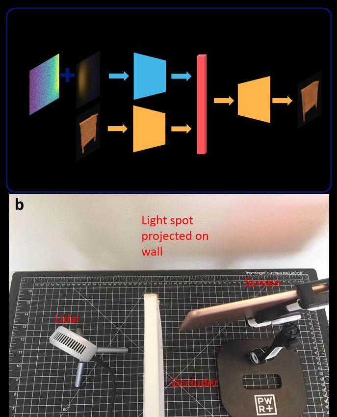
provides much more information than a passive image and
much higher degree of freedom for NLOS imaging and re-
construction. This genre usually applies a laser to scan
the scene spatially, and a photon detector is used to de-
tect the transient events of back-scattered photons. The
NLOS reconstruction is then achieved by analyzing the
back-projection conditions of the transients or through other
geometric optical transformations [3, 47]. The algorithms
may proceed iteratively until the reconstruction converges.
The active scheme can achieve high fidelity of NLOS re-
construction, meanwhile, some major shortcomings hinder
the universal application of this NLOS imaging approach.
On the physical level, the laser scanning and transient de-
tection processes are necessary. The laser scanning pro-
cess may take minutes to hours, which is not applicable
to real-time scenarios, and the ultrafast lasers are expen-
sive and may not satisfy the safe standard for out-of-lab
applications. As for the detection equipment, the transient          Figure 2. Two cases of Lidar detection (top view). (a) At most
events require self-built optical systems with sophisticated         points when the light directly reflected from the wall is far stronger
apparatus, such as single-photon avalanche photodetectors            than the light experiencing multiple reflections, the Lidar will de-
(SPAD), ultrafast photon counting modules, streak cameras,           note the correct depth as the actual distance between itself and the
etc [19, 6, 24]. The overall equipment setting is highly com-        wall. (b) If one beam undergoing multiple reflection is more in-
plicated and vulnerable to ambient perturbation, which is            tense than the direct-reflected light, the Lidar will store the inten-
                                                                     sity of multi-reflected light and treat the multi-reflection light path
more likely to occur in ultrafast optical experiments rather
                                                                     as the direct-reflected one, which lead to a ‘fake detected depth’.
than real-world imaging scenes. At the algorithm level, the
transient detection will collect huge amount of data, and the
reconstruction process always deals with matrices or tensors
of gigantic sizes. These properties lead to high consump-            data and target NLOS scenes. However, in sharp contrast
tion of memory, storage and computational resources, and             to most computer vision tasks, in NLOS reconstruction the
the reconstruction time will hardly fulfill the expectation of       input data and output scenes share almost no common ge-
real-time NLOS imaging and reconstruction.                           ometric features, thus the supervised mapping of input and
                                                                     the label (i.e. the ground truth NLOS scene) may not be
    To address these pressing challenges, in this paper we           well-learnt by a conventional convolutional neural network
introduce a novel methodology for real time NLOS imag-               (CNN) [31, 29]. Besides, generating high dimensional data
ing. Instead of using devices for transient experiment, we           with explicit semantics, such as images or 3D scenes, is
employ a low-end Lidar as both the probe and detection de-           never a closed-form problem, and a generative model such
vices [48]. Compared with in-lab scanning systems with               as generative adversarial network (GAN) or variational au-
ultrafast laser and SPAD, Lidar is commercially available at         toencoder (VAE) is necessary [20, 27]. Therefore, the re-
much lower prices (only a few hundred dollars), with much            construction performances of these reported methods are
faster operation speed (scanning time at millisecond level)          limited by the direct mapping with supervised learning. In
and strong robustness to environmental factors. Not relying          this work we propose a deep learning framework that con-
on transient time-of-flight (ToF) information of photons, we         sists of two components and achieves NLOS reconstruction
utilize the depth map and intensity map collected by the Li-         in two steps. The generator is the decoder of a trained VAE
dar to achieve real-time, full-color NLOS imaging. Our al-           which is responsible for generating various scenes, and the
gorithm is deep learning based and consists of two neural            CNN compressor is to convert the detected depth and in-
networks: a compressor and a generator [30]. There are               tensity information into a low-dimensional latent space for
some pioneering works that have introduced deep learning             the generator. When the Lidar collects new depth and in-
into NLOS imaging and revealed the promising future of               tensity maps, the compressor will compress them into a la-
deep learning assisted NLOS imaging [13, 14, 32, 34, 2].             tent vector, then the generator will recover the NLOS scene
The reconstruction speeds of deep learning approaches are            by decoding the vector. This methodology overcomes the
inherently much faster than geometric optics-based meth-             flaws of previous deep learning approaches, which were
ods, with better versatility and generalization abilities. The       based on a single network and trained in supervised fash-
reported methods have relied on supervised learning, which           ion. Our framework is capable of achieving state-of-the-art
try to establish the direct mapping between the detected             reconstruction performance, with strong robustness to am-

                                                                 2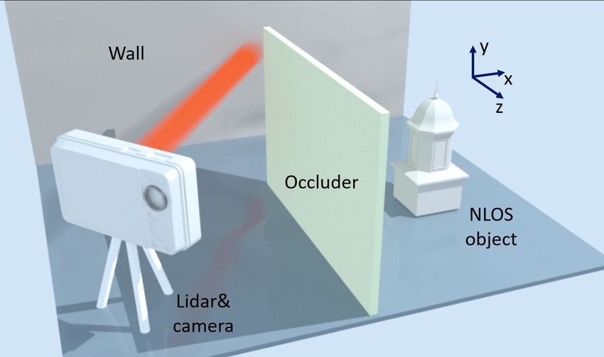
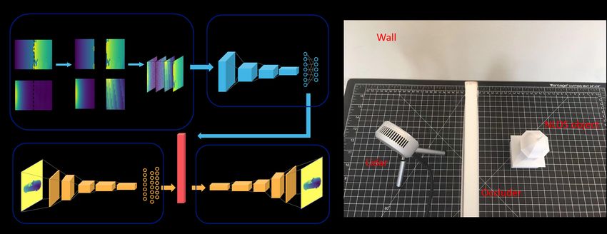
Figure 3. (a) Algorithm workflow and (b) experimental setup for NLOS imaging. (a) The NLOS reconstruction framework consists of
two neural networks, a generator and a compressor. The reconstruction process is two-step: the compressor compresses the detected data
as a latent vector, the generator then decodes the latent vector into a depth map of the NLOS object. The compressor is adapted from
MobileNetV2, and the generator is the decoder of a variational autoencoder (VAE) with ResNet blocks. The input contains the depth
and intensity maps detected by the Lidar, stacked as a 4-channel tensor with channel-wise normalization and Gaussian noises. (b) The
experimental setup for NLOS imaging used in this work.

bient surroundings and the position, gesture and viewpoint            laser in all directions to scan the environment and then col-
of the NLOS objects. We have demonstrated the function-               lecting the perturbed photon distributions. Here we use a
ality of our approach on a synthetic dataset, then applied            low-cost Lidar (Intel Realsense) as both the laser source
transfer learning and testify the performance through real-           and the camera. The laser beam on the Lidar scans the
world experiments. To illustrate the versatility of our ap-           field of view (FOV) of 70 by 55 degrees, then the detec-
proach which is not limited to the reconstruction of ge-              tor on it sequentially collects the photons reflected from the
ometric features of NLOS scenes, we step further to ex-               surrounding objects. Based on the time of flight (ToF) in-
perimentally prove the effectiveness of our method for re-            formation of the received photons, the Lidar will generate
covery of full-color information. The methodology pre-                a depth map and a light intensity map. It is worth noting
sented here potentially offers a paradigm shift for appli-            that the Lidar used in our method is not for detecting tran-
cations of real-time NLOS imaging, such as driving assis-             sient events, since the resolution and detection mechanism
tant, geological prospecting, medical imaging, and many               are different from the equipment specifically intended for
more [28, 44, 43, 18, 11, 26, 50, 37, 35].                            transient experiments. The depth and intensity maps are in-
                                                                      ferred based on the general ToF photon distribution, which
2. Methods                                                            allows us to acquire both LOS and NLOS knowledge. As il-
                                                                      lustrated in Fig. 2, when the laser is near-normal incident on
2.1. Lidar-based detection                                            the wall (Fig. 2a), most of the photons received by the Li-
   The typical NLOS imaging scenario is depicted in Fig. 1.           dar are the ones directly reflected back and travel along the
When an obstacle blocks the direct light path between                 reverse light path. There are also photons deflected by the
the object and the camera, the conventional LOS imaging               wall to different directions, further scattered by surround-
would fail to function as the detector receives no direct in-         ing objects and finally collected by the Lidar. However, the
formation from the target. However, another object or wall            light intensities along these multi-reflection pathways will
between the camera and the target may serve as a ‘relay sta-          be much lower than that of the direct-reflected light. Thus
tion’ and provide indirect light path for NLOS imaging: a             in the case of Fig. 2a, the Lidar will count the travel time
photon sent from the object can be reflected by the relay             of the direct-reflected photons and the calculated depth will
object and further collected by the camera. After that, the           represent the orthogonal distance between the Lidar plane
information of both the target object and the relay object is         and the incidence point on the wall, which is typical for the
embedded in the photon distribution received by the camera.           regular Lidar operation.
To disentangle the two sources of data, we need to actively               In another case (Fig. 2b), if the incidence angle is oblique
probe the surroundings to extract data under different per-           and the point of illumination on the wall is close to the target
turbations. The probe is usually conducted through sending            object, the light intensity along the ‘Lidar-wall-object-wall-

                                                                  3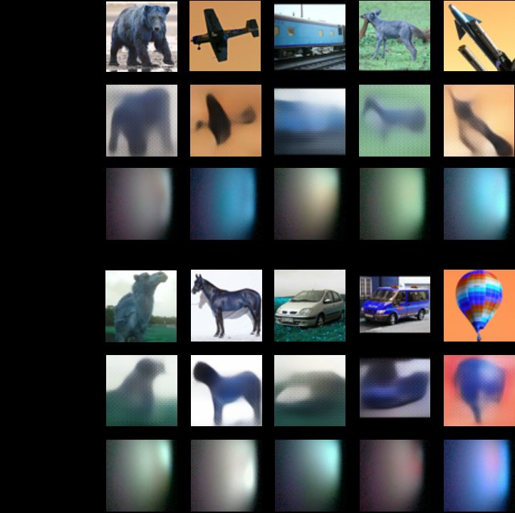
Lidar’ path may be stronger than the direct ‘Lidar-wall-              A typical CNN-based VAE consists of an encoder and a de-
Lidar’ light. As a result, the Lidar will denote the distance         coder with mirror structures to each other. The VAE applied
as half of the multi-reflection light path, i.e., the NLOS dis-       here is composed of ResNet blocks to improve the resolving
tance, rather than the direct distance. Although this scenario        power and training effectiveness, and we denote it as Res-
is undesired in conventional Lidar applications, it is favor-         VAE [21]. Specifically, the encoder down-samples an input
able in NLOS imaging. In the common case as shown in                  image x (64 by 64 in our experiments) to a 256-dimension
Fig. 2a, the Lidar will provide the correct depth and inten-          latent vector z, which means the encoder learns the poste-
sity, and these information represents the geometric features         rior p(z|x), and z is reparameterized to force its distribu-
of the relay wall, which also implies the position of the Li-         tion p(z) to be a standard Gaussian distribution. Further,
dar relative to the wall. While in the NLOS case (Fig. 2b),           the decoder (p(x0 |z)) expands z to a reconstructed image
the light path involves multiple reflection, the distance doc-        x0 . The training process is to lower the difference between
umented by the Lidar is not the same as the distance be-              x and x0 (reconstruction loss), as well as the distance be-
tween the Lidar and the wall, and the back-scattered light            tween p(z) and a standard Gaussian distribution (Kullback-
may not follow the path of the incoming beam. Although                Leibler divergence). Once the training is finished, the de-
the received photons by the Lidar contain information of              coder will be able to generate images similar to the ones
actual light intensities and light paths, the Lidar will in-          in the training dataset, and the latent vectors can be ran-
correctly map them to ‘fake’ locations. In this way, the              domly sampled from the standard Gaussian distribution. In
ground truth photon distribution that reveals the NLOS in-            our case, the input x is the depth map of the NLOS scene
formation will be distorted and overshadowed by the Lidar             relative to the wall, which corresponds to the perpendicular
mechanism. Our methodology focuses on redistributing the              distances between the wall and the elements on the point
intensity and depth maps to recover the original NLOS in-             clouds of NLOS objects. Since the mapping between x and
formation and thus achieving imaging and reconstruction in            z is mostly one-to-one, the reconstruction is no longer nec-
a highly efficient and faithful manner.                               essary to transform the detected information y to a high-
                                                                      dimension x. Instead, it only needs to compress y to a low
2.2. Two-step deep remapping framework                                dimensional vector z, which can be facilitated by a CNN-
                                                                      based compressor. The role of the compressor is rather stan-
   Since the redistributing or remapping function varies
                                                                      dard in computer vision, which is fed with images and gen-
with different NLOS scenes, it is reasonable to apply deep
                                                                      erates the predicted labels. Here the compressor is adapted
learning to learn the connection between the ground truth
                                                                      from a lightweight network, MobileNetV2, to achieve good
NLOS objects and detected maps of depth and intensity.
                                                                      performance and avoid overfitting [40]. The input of the
There are some pioneering works introducing supervised
                                                                      compressor is the depth-and-intensity map detected by the
learning and applying a deep neural network (NN, such
                                                                      Lidar, and the output predicts the latent vectors of the target
as U-Net [39]) into NLOS imaging. However, a single
                                                                      NLOS depth map encoded by the pretrained Res-VAE.
NN is not sufficient to transform the detected informa-
tion into clear NLOS scenes as expected. The remapping                3. Experiments
task has two intrinsic requirements: (1) transform the col-
lected information into NLOS representations, and (2) gen-               To validate the efficacy of the Lidar-based approach and
erate NLOS scenes with clean semantics. As a result, a                the deep learning reconstruction algorithm, we have con-
regression-oriented NN trained in supervised fashion can-             ducted 4 categories of experiments. The first one is based
not simultaneously meet the two requirements with good                on a synthetic dataset, and the second experiment is on real
performance. In contrast, here we propose a reconstruc-               objects with transfer learning applied. We further demon-
tion framework consisting of two networks, each fulfilling            strate the power of our method for full-color NLOS imag-
one requirement: a compressor will transform the detected             ing, with experiments on images of everyday objects and
depth and intensity maps into a latent vector, and a gener-           complex scenes, respectively.
ator will decode the latent vector to the predicted NLOS
scene. With the sequential functions of the two compo-                3.1. Experiment on a synthetic dataset
nents, the algorithm can reconstruct NLOS scenes with high            NLOS renderer. We first train and test the functionality
fidelity, comparable to the performance of state-of-the-art           of our framework on a synthetic dataset, and the weights
transient-based methods, with a processing time of no more            can be further optimized when applied to real-world exper-
than milliseconds.                                                    iments through transfer learning. The synthetic dataset is
   The pipeline of the framework is depicted in Fig. 3a. The          composed of the NLOS depth maps and the correspond-
generator is the decoder of a VAE. Similar to GAN, VAE is             ing simulated depth and intensity maps detected by the Li-
a powerful tool for scene and image synthesis, and offers             dar. As a result, a NLOS renderer is necessary to simulate
better controllability on the sampling of the latent space.           the behavior of the Lidar [25]. In the implementation of

                                                                  4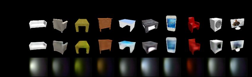
Figure 4. The NLOS reconstruction experiment on a synthetic dataset. The reconstruction results of randomly selected everyday items in
the test set are presented. The first row is the ground truth depth maps of the items, and the second row shows the reconstructed depth maps.
The last row presents the inputs for the NLOS reconstruction, which are the simulated depth and intensity maps by our NLOS renderer.
Since we assume the NLOS objects are situated on the right of the Lidar, the left-half parts of the depth and intensity maps are almost
identical for different items. Therefore, here we only present the right-half parts of these maps. For each case, the left image represents the
depth map, and the one on the right is for the intensity.

the renderer, we assume all surfaces of the wall and the                  only seconds, which is much more efficient than traditional
objects are Lambertian. The surfaces can also be set as                   ray-tracing renderers. The targets for rendering are around
any customized bidirectional reflectance distribution func-               30,800 depth maps of everyday objects (cars, tables, lamps,
tion (BRDF), while here we use uniform Lambertian for                     boats, chairs, etc.) from ShapeNet [12, 51]. To improve the
general purpose. The renderer assumes millions of beams                   variance of the dataset, the objects are situated with various
will be sent along all directions in the FOV of the Lidar,                attitudes, angles and distances to the wall.
and for each beam the depth and intensity will be calcu-
lated based on the reflected light. For a beam sent to a                  Networks training. Once the dataset is formed, it is time
specific direction, the direct-reflected distance r is just the           to train the neural networks in our framework. The Res-
light path between the Lidar position and the projected point             VAE needs to be trained first since we need to push the
on the wall, and the direct-reflected intensity is denoted as             corresponding latent vectors of the depth maps into a dic-
I0 /r2 , where I0 is the total intensity and set as I0 = 1                tionary. During the training of Res-VAE, the Kullback-
for simplicity. In the meantime, the multi-reflected dis-                 Leibler distance is not necessary to be suppressed to a very
tance and intensity is calculated based on the ‘Lidar-wall-               low level, since the compressor will infer the prior distri-
object-wall-Lidar’ light path, which is the so-called three-              bution p(z) through p(z|y), so it is insignificant if p(z) is
bounce simulation. Higher-order bounces are also possible                 not strictly Gaussian. With the acquisition of the latent vec-
but the intensities will be too low to make any difference                tors, the compressor is trained to map the rendered depth
in our setting. The intensity for each three-bounce beam                  and intensity maps to the latent vectors. As illustrated in
is inversely proportional to the chain-product of squares of              Figs. 1 and 3b, we assume the Lidar is located on the left
light paths between every bounces. Besides, the cosine be-                of the object, so the left half parts of the depth and in-
tween the light direction and the normal vector →    −
                                                     n of the             tensity maps will mostly denote the trivial information of
                                                   →
                                                   −
reflected surface will also be considered, where n is calcu-              the wall, while the right parts are encoded with the infor-
lated based on the gradient of surface depth. Since there are             mation of both the wall and the NLOS objects. The right
millions of possible multi-reflected paths, we collectively               half parts of the depth maps correspond to larger distances,
group them into bins with resolution of 0.01m, and the in-                thereby leading to weaker intensities. To prevent the subtle
tensity for one bin is the intensity summation of all the pos-            signals on the right from being flooded by the overwhelm-
sible light paths whose lengths fall within the bin. After                ing information on the left, we manually split the maps to
that, the simulated light intensity of this scanning point will           the left and right halves, and vertically stack them into a 4-
be the maximum between all the multi-reflected and direct-                channel input image (ordered as right-depth, right-intensity,
reflected intensities, and the simulated depth will be the cor-           left-depth, left-intensity), with each channel normalized in-
responding distance multiplied by the cosine between the                  dependently as illustrated in Fig. 3(a). Besides, the left-
incidence direction and the normal vector of Lidar plane.                 depth and left-intensity are almost the same for different
The final depth intensity maps consist of 80 by 64 pixels.                data points since they only document the LOS information
Since the renderer conducts matrix operations and multi-                  of the wall. Hence, we introduce Gaussian noises to these
processing calculation, the rendering for one object takes                two channels in order to add randomness and prevent over-
                                                                          fitting. The 30,800 data points are randomly split into a

                                                                      5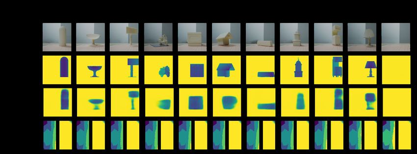
Figure 5. The NLOS reconstruction experiment on real objects. The first row displays the pictures of the actual objects used in this
experiment, and the second row corresponding to the depth labels for training. The reconstructed depth maps are shown in the third row.
The last row presents the inputs for the NLOS reconstruction, which are the depth and intensity maps collected by the Lidar (right-half
parts only as explained before).

training dataset of 24,600 and a test dataset of 6,200. The           dataset with around 1,900 NLOS cases. Although the gen-
details of the training process and the structures of the gen-        erator does not need to retrain, the compressor trained on
erator and the compressor are provided in the Supplemen-              the synthetic dataset is not directly applicable to the real-
tary Material.                                                        world environment. Besides, such a tiny dataset (randomly
Reconstruction performance. With the training of both                 split into 1,600 as the training dataset and 300 as the test set)
the generator and the compressor, we will be able to predict          is not compatible to a large-scale network since overfitting
the NLOS scenes based on the captured depth and intensity             will be unavoidable, and a simple network will not be able
maps. The NLOS reconstruction results of different cat-               to handle the task. In this case, we leverage transfer learning
egories of ShapeNet-items from the test dataset are plotted           to mitigate the training dilemma and transfer the knowledge
in Fig. 4. The first two rows are the ground truth depth maps         that the compressor has learnt from the synthetic dataset to
and the reconstructed results, respectively. The third row of         the real-world dataset. The target labels for the compressor
the figure presents the rendered depth and intensity maps             are the latent vectors of the virtual depth maps correspond-
which are used as the input for the reconstruction frame-             ing to the 1,900 scenes. As the compressor has been previ-
work. Since their left-half parts are almost identical and            ously trained on the synthetic dataset, we continue to train
indistinguishable to the eye, we only show their right-half           it on the real-world training dataset for several epochs until
parts for each case. Although the examples are randomly               the training loss and test loss are about to diverge. Next,
chosen and with a wide range of shapes, the reconstruction            we freeze all the network weights except for the last linear
algorithm is able to recover the significant features of them.        layer, and train it until the loss becomes steady. The entire
This experiment demonstrates the high quality of the NLOS             process of the transfer learning takes only a couple of min-
imaging through the developed method in this work.                    utes, and the reconstruction performance on the test dataset
                                                                      is displayed in Fig. 5. Each column presents one example,
3.2. Real-world NLOS reconstruction
                                                                      and the four rows are the pictures of the actual objects, the
   Having confirmed the performance of our NLOS imag-                 virtual depth labels, the reconstructed depth maps, and the
ing method on the synthetic dataset, we further apply it              right-halves of detected depth and intensity maps, respec-
to real-world NLOS scenes. In real-world applications we              tively. It is noticeable that our methodology is able to recon-
usually cannot conduct an enormous amount of detections               struct sufficient geometric and positional information of the
to generate a big training dataset, therefore we utilize the          NLOS objects. And if there is nothing behind the occluder,
networks with weights pretrained on the synthetic dataset,            the framework will not provide a false-positive NLOS re-
further continue to train the networks on a relatively small          sult. Certain details are not fully recovered, which is ex-
real-world dataset through transfer learning. We have 54              pected since some of the reflected light cannot be captured
3D-printed objects as the target objects, which are models            by the Lidar, thus the information loss is inevitable. Never-
of common objects like buses, tables, pianos, etc. The ex-            theless, the reconstruction quality is comparable or superior
perimental environment is presented in Fig. 3b, with the ob-          to those of the state-of-the-art methods, with much lower
jects are positioned at 9 different locations with 5 rotational       requirements on equipment and ambient environment along
angles (rotation only for non-circular items), generating a           with much faster imaging speed.

                                                                  6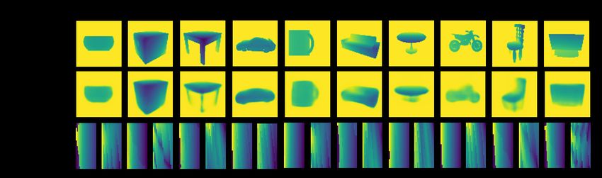
3.3. Full-color NLOS imaging
    NLOS reconstruction mostly refers to the reconstruction
of the geometric features of NLOS objects, while regular
LOS imaging also captures and records the color informa-
tion. Here we step forward to demonstrate the capacity
of our methodology for the recovery of NLOS scenes with
color information.
    Most commercial Lidars utilize infrared laser to perceive
the surrounding environment. However, it is impossible
to detect the color information in the visible wavelength
range through an infrared laser at a single wavelength. One
promising solution is to build an optical system with red,
green and blue (RGB) lasers as the scanning seed [13].
While stick to commercially available devices, we demon-
strate a Lidar and a camera are able to cooperatively recover
the color images displayed in the NLOS scenes. Since the
Lidar is also equipped with a camera, we do not need to add
additional cameras or components to the system. The exper-
imental setup for full-color NLOS imaging is illustrated in
Fig. 6b. A screen displays images but is invisible to the cam-
era, while we aim to recover the colored images based on
the light spots projected on the wall. In this experiment, the        Figure 6. (a) Algorithm workflow and (b) experimental setup for
reconstruction objective will not be single-channel depth             full-color NLOS imaging. (a) The algorithm is essentially the
maps, but three-channel RGB images [41]. The algorithm                same as the one presented in Fig. 3, while the input here is the
is similar to previous, as depicted in Fig. 6a. The training          concatenated tensor of captured RGB light spot image and the
dataset is composed of RGB images of everyday objects.                depth map with Gaussian noise. The reconstruction objective is
Each time the screen displays a new image, the camera will            to obtain the full-color image. (b) When the screen displays an
                                                                      image, the device is able to detect the depth map along with the
capture an image of the light spot on the wall, and the Li-
                                                                      light spot projected on the wall, which will be used for full-color
dar also denotes the depth map. We have collected 48,800
                                                                      NLOS imaging.
data points and 43,000 of them are divided into a training
set. During the training phase, the Res-VAE is trained to
generate RGB images of the objects, and the latent vectors            the shape and color of nonluminous objects.
of the images in the training set are documented. As for
the compressor, the input is a 4-channel tensor, which is             3.4. Full-color NLOS imaging for complex scenes
stacked with the RGB image collected by the camera along
with the depth map detected by the Lidar. Since different                 A mature imaging technique should not have constraints
images will not influence the depth map, we can use one               on the number of objects to be captured, and the imag-
static depth map with random Gaussian noise to cover all              ing quality should not degrade with the increased complex-
the cases for full-color NLOS imaging, which is the one               ity of the scene. To explore the full capacity of our solu-
denoted in Fig. 6a. The depth maps will function more                 tion, we test it on a much more complicated RGB dataset,
significantly if the angle and position of the Lidar are dy-          STL10 [15]. Instead of images of isolated objects in pure
namic, which is left to future research. To illustrate that the       black background, STL10 contains real pictures taken with
functionality of our NLOS framework is not limited to spe-            different devices, angles, positions, and surrounding envi-
cific neural networks, here the compressor is adapted from            ronments. The pictures may have more than one objects,
ResNet50, which is also more compatible to the large-scale            and the semantic meanings are intricate and entangled with
dataset with RGB information. The reconstructed RGB im-               each other. To accommodate the increased amount of in-
ages of different categories of everyday items are displayed          formation in the image, we extend the dimension of the la-
in Fig. 7, with original images, reconstructed images, and            tent vector from 256 to 512, while other parameters and the
light spots aligned from the top row to the bottom. It is ev-         training pipeline remain the same as the previous experi-
idenced that the geometric features and color information             ment. Some examples from the test set (50,000 data in the
are retained to a great extent, which validates the capac-            training set, 10,000 in the test set) are presented in Fig. 8.
ity of the proposed approach. Providing the RGB scanning              Since the images in STL10 are not well-categorized, the ex-
light source is introduced, we will be able to recover both           amples are randomly picked from the whole test set. It is

                                                                  7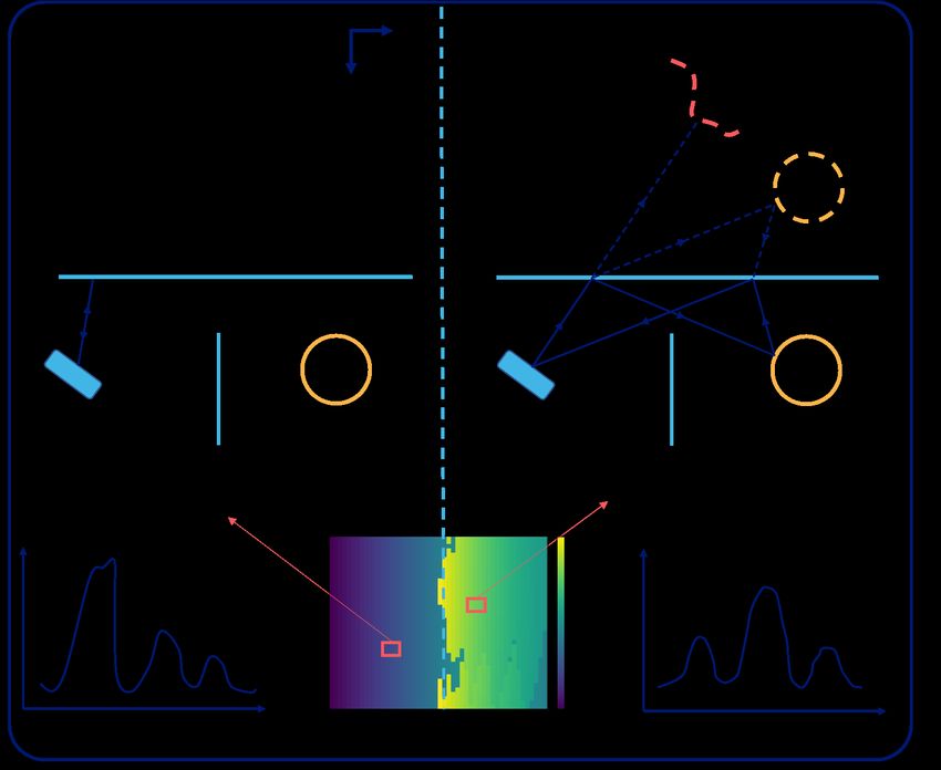
Figure 7. Full-color NLOS reconstruction experiment on displayed images of everyday items. The results of different categories of everyday
items are presented, with the first row as the original images, and the second row as the reconstructed full-color images. The third row
presents the light spots captured by the camera on the Lidar.

                                                                           ronment. Algorithmically, we have proposed a deep learn-
                                                                           ing framework consisting of two networks, a compressor
                                                                           and a generator. The framework is not trained in the typical
                                                                           manner of supervised learning, and the reconstruction pro-
                                                                           cess is two-step. The efficacy of the methodology has been
                                                                           verified experimentally, on both real-object NLOS recon-
                                                                           struction as well as full-color NLOS imaging, with state-
                                                                           of-the-art performance. Our approach is directly pertinent
                                                                           to some real-world applications, such as corner-detection
                                                                           for driverless cars, NLOS remote sensing, NLOS medical
                                                                           imaging, to name a few.

                                                                              We realize additional efforts are needed to bring the pro-
                                                                           posed method to perfection. The Lidar used in this work
                                                                           has a very low laser power, which is designed for in-door
Figure 8. Full-color NLOS reconstruction experiment on displayed           detections at short distance. We plan to transfer our tech-
images of complex scenes. Randomly selected examples from the              nique to high-performance Lidars, such as those equipped
whole test set are presented, with the original images, the recon-         on self-driving cars, to fulfill large-scale NLOS tasks, in-
structed full-color images, and the light spots captured by the cam-       cluding but not limited to NLOS imaging of street scenes,
era on the Lidar are shown sequentially.                                   buildings, and vehicles. Other follow-up efforts include the
                                                                           introduction of RGB light sources for full-color detection
noticeable that major profiles and color information are cor-              of nonluminous objects, development of techniques to dis-
rectly unfolded, while some fine details are sacrificed. The               entangle the effects of positions and angles of Lidar, etc.
performance is mainly limited by the generative capability                 As for the algorithm, the projected bottleneck for complex
of the generator. Introducing advanced VAE models, such                    NLOS tasks will be the generative capability of the gener-
as β-VAE, IntroVAE, VQ-VAE-2, is expected to mitigate                      ator. Compared to GANs, the generated images of most
this issue [10, 23, 38].                                                   VAEs are blurrier. Introducing most advanced VAE ar-
                                                                           chitectures is expected to resolve this problem. Since the
4. Conclusion and discussion                                               compressor is responsible for extracting NLOS information
                                                                           from the depth and intensity maps, it would be favorable
   We have developed a general methodology for real-time                   to update attention blocks to energize the compressor with
NLOS imaging, with innovation in both imaging equip-                       better efficiency on locating the NLOS features. In addi-
ment and reconstruction algorithm. Physically, we choose                   tion, instead of training the generator and the compressor
low-cost Lidar to replace complicated devices commonly                     sequentially as performed in this work, we expect improved
used for ultrafast experiment, and our scheme features much                performance if they are trained concurrently, similar to the
faster detection speed and better robustness to ambient envi-              mechanism of GAN.

                                                                       8
5. Acknowledgements [13] Wenzheng Chen, Simon Daneau, Fahim Mannan, and Felix
Heide. Steady-state non-line-of-sight imaging. In Proceed-
We thanks Su Li from Taxes A&M University and ings of the IEEE Conference on Computer Vision and Pattern
Jingzhi Hu from Peking University for fruitful discussions. Recognition, pages 6790–6799, 2019. 2, 7
[14] Javier Grau Chopite, Matthias B Hullin, Michael Wand, and
References Julian Iseringhausen. Deep non-line-of-sight reconstruction.
In Proceedings of the IEEE/CVF Conference on Computer
[1] Byeongjoo Ahn, Akshat Dave, Ashok Veeraraghavan, Ioan- Vision and Pattern Recognition, pages 960–969, 2020. 2
nis Gkioulekas, and Aswin C Sankaranarayanan. Convolu- [15] Adam Coates, Andrew Ng, and Honglak Lee. An analysis
tional approximations to the general non-line-of-sight imag- of single-layer networks in unsupervised feature learning.
ing operator. In Proceedings of the IEEE International Con- volume 15 of Proceedings of Machine Learning Research,
ference on Computer Vision, pages 7889–7899, 2019. 1 pages 215–223, 11–13 Apr 2011. 7
[2] Miika Aittala, Prafull Sharma, Lukas Murmann, Adam [16] Boguslaw Cyganek and J Paul Siebert. An introduction to
Yedidia, Gregory Wornell, Bill Freeman, and Frédo Durand. 3D computer vision techniques and algorithms. John Wiley
Computational mirrors: Blind inverse light transport by deep & Sons, 2011. 1
matrix factorization. In Advances in Neural Information Pro- [17] Daniele Faccio, Andreas Velten, and Gordon Wetzstein.
cessing Systems, pages 14311–14321, 2019. 1, 2 Non-line-of-sight imaging. Nature Reviews Physics, pages
[3] Victor Arellano, Diego Gutierrez, and Adrian Jarabo. Fast 1–10, 2020. 1
back-projection for non-line of sight reconstruction. Optics [18] Genevieve Gariepy, Francesco Tonolini, Robert Henderson,
express, 25(10):11574–11583, 2017. 2 Jonathan Leach, and Daniele Faccio. Detection and track-
[4] Manel Baradad, Vickie Ye, Adam B. Yedidia, Frédo Durand, ing of moving objects hidden from view. Nature Photonics,
William T. Freeman, Gregory W. Wornell, and Antonio Tor- 10(1):23–26, 2016. 1, 3
ralba. Inferring light fields from shadows. In Proceedings [19] Massimo Ghioni, Angelo Gulinatti, Ivan Rech, Franco
of the IEEE Conference on Computer Vision and Pattern Zappa, and Sergio Cova. Progress in silicon single-photon
Recognition (CVPR), June 2018. 1 avalanche diodes. IEEE Journal of selected topics in quan-
[5] Mufeed Batarseh, Sergey Sukhov, Zhiqin Shen, Heath tum electronics, 13(4):852–862, 2007. 2
Gemar, Reza Rezvani, and Aristide Dogariu. Passive sensing [20] Ian Goodfellow, Jean Pouget-Abadie, Mehdi Mirza, Bing
around the corner using spatial coherence. Nature communi- Xu, David Warde-Farley, Sherjil Ozair, Aaron Courville, and
cations, 9(1):1–6, 2018. 1 Yoshua Bengio. Generative adversarial nets. In Advances
[6] Wolfgang Becker. Advanced time-correlated single photon in neural information processing systems, pages 2672–2680,
counting techniques, volume 81. Springer Science & Busi- 2014. 2
ness Media, 2005. 2 [21] Kaiming He, Xiangyu Zhang, Shaoqing Ren, and Jian Sun.
[7] Jacopo Bertolotti, Elbert G Van Putten, Christian Blum, Deep residual learning for image recognition. In Proceed-
Ad Lagendijk, Willem L Vos, and Allard P Mosk. Non- ings of the IEEE conference on computer vision and pattern
invasive imaging through opaque scattering layers. Nature, recognition, pages 770–778, 2016. 4
491(7423):232–234, 2012. 1 [22] Felix Heide, Lei Xiao, Wolfgang Heidrich, and Matthias B
[8] Jeremy Boger-Lombard and Ori Katz. Passive optical time- Hullin. Diffuse mirrors: 3d reconstruction from diffuse in-
of-flight for non line-of-sight localization. Nature communi- direct illumination using inexpensive time-of-flight sensors.
cations, 10(1):1–9, 2019. 1 In Proceedings of the IEEE Conference on Computer Vision
[9] Katherine L Bouman, Vickie Ye, Adam B Yedidia, Frédo and Pattern Recognition, pages 3222–3229, 2014. 1
Durand, Gregory W Wornell, Antonio Torralba, and [23] Huaibo Huang, Ran He, Zhenan Sun, Tieniu Tan, et al.
William T Freeman. Turning corners into cameras: Princi- Introvae: Introspective variational autoencoders for photo-
ples and methods. In Proceedings of the IEEE International graphic image synthesis. In Advances in neural information
Conference on Computer Vision, pages 2270–2278, 2017. 1 processing systems, pages 52–63, 2018. 8
[10] Christopher P Burgess, Irina Higgins, Arka Pal, Loic [24] J Itatani, F Quéré, Gennady L Yudin, M Yu Ivanov, Fer-
Matthey, Nick Watters, Guillaume Desjardins, and Alexan- enc Krausz, and Paul B Corkum. Attosecond streak camera.
der Lerchner. Understanding disentangling in β-vae. arXiv Physical review letters, 88(17):173903, 2002. 2
preprint arXiv:1804.03599, 2018. 8 [25] Adrian Jarabo, Julio Marco, Adolfo Muñoz, Raul Buisan,
[11] Susan Chan, Ryan E Warburton, Genevieve Gariepy, Wojciech Jarosz, and Diego Gutierrez. A framework for
Jonathan Leach, and Daniele Faccio. Non-line-of-sight transient rendering. ACM Transactions on Graphics (ToG),
tracking of people at long range. Optics express, 33(6):1–10, 2014. 4
25(9):10109–10117, 2017. 3 [26] Ori Katz, Pierre Heidmann, Mathias Fink, and Sylvain Gi-
[12] Angel X Chang, Thomas Funkhouser, Leonidas Guibas, gan. Non-invasive single-shot imaging through scattering
Pat Hanrahan, Qixing Huang, Zimo Li, Silvio Savarese, layers and around corners via speckle correlations. Nature
Manolis Savva, Shuran Song, Hao Su, et al. Shapenet: photonics, 8(10):784–790, 2014. 3
An information-rich 3d model repository. arXiv preprint [27] Diederik P Kingma and Max Welling. Auto-encoding varia-
arXiv:1512.03012, 2015. 5 tional bayes. arXiv preprint arXiv:1312.6114, 2013. 2
9[28] Jonathan Klein, Christoph Peters, Jaime Martı́n, Martin Lau- [42] Ashutosh Saxena, Sung Chung, and Andrew Ng. Learning
renzis, and Matthias B Hullin. Tracking objects outside the depth from single monocular images. Advances in neural
line of sight using 2d intensity images. Scientific reports, information processing systems, 18:1161–1168, 2005. 1
6(1):1–9, 2016. 3 [43] Nicolas Scheiner, Florian Kraus, Fangyin Wei, Buu Phan,
[29] Alex Krizhevsky, Ilya Sutskever, and Geoffrey E Hinton. Fahim Mannan, Nils Appenrodt, Werner Ritter, Jurgen Dick-
Imagenet classification with deep convolutional neural net- mann, Klaus Dietmayer, Bernhard Sick, and Felix Heide.
works. Communications of the ACM, 60(6):84–90, 2017. 2 Seeing around street corners: Non-line-of-sight detection
[30] Yann LeCun, Yoshua Bengio, and Geoffrey Hinton. Deep and tracking in-the-wild using doppler radar. In Proceed-
learning. nature, 521(7553):436–444, 2015. 2 ings of the IEEE/CVF Conference on Computer Vision and
[31] Yann LeCun, Léon Bottou, Yoshua Bengio, and Patrick Pattern Recognition, pages 2068–2077, 2020. 3
Haffner. Gradient-based learning applied to document recog- [44] Brandon M. Smith, Matthew O’Toole, and Mohit Gupta.
nition. Proceedings of the IEEE, 86(11):2278–2324, 1998. Tracking multiple objects outside the line of sight using
2 speckle imaging. In Proceedings of the IEEE Conference
[32] Xin Lei, Liangyu He, Yixuan Tan, Ken Xingze Wang, Xing- on Computer Vision and Pattern Recognition (CVPR), June
gang Wang, Yihan Du, Shanhui Fan, and Zongfu Yu. Direct 2018. 3
object recognition without line-of-sight using optical coher- [45] Christos Thrampoulidis, Gal Shulkind, Feihu Xu, William T
ence. In Proceedings of the IEEE Conference on Computer Freeman, Jeffrey H Shapiro, Antonio Torralba, Franco NC
Vision and Pattern Recognition, pages 11737–11746, 2019. Wong, and Gregory W Wornell. Exploiting occlusion in non-
2 line-of-sight active imaging. IEEE Transactions on Compu-
[33] Xiaochun Liu, Ibón Guillén, Marco La Manna, Ji Hyun tational Imaging, 4(3):419–431, 2018. 1
Nam, Syed Azer Reza, Toan Huu Le, Adrian Jarabo, [46] Chia-Yin Tsai, Kiriakos N Kutulakos, Srinivasa G
Diego Gutierrez, and Andreas Velten. Non-line-of-sight Narasimhan, and Aswin C Sankaranarayanan. The geom-
imaging using phasor-field virtual wave optics. Nature, etry of first-returning photons for non-line-of-sight imaging.
572(7771):620–623, 2019. 1 In Proceedings of the IEEE Conference on Computer Vision
[34] Christopher A Metzler, Felix Heide, Prasana Rangarajan, and Pattern Recognition, pages 7216–7224, 2017. 1
Muralidhar Madabhushi Balaji, Aparna Viswanath, Ashok [47] Andreas Velten, Thomas Willwacher, Otkrist Gupta, Ashok
Veeraraghavan, and Richard G Baraniuk. Deep-inverse cor- Veeraraghavan, Moungi G Bawendi, and Ramesh Raskar.
relography: towards real-time high-resolution non-line-of- Recovering three-dimensional shape around a corner using
sight imaging. Optica, 7(1):63–71, 2020. 2 ultrafast time-of-flight imaging. Nature communications,
[35] Ji Hyun Nam, Eric Brandt, Sebastian Bauer, Xiaochun Liu, 3(1):1–8, 2012. 1, 2
Eftychios Sifakis, and Andreas Velten. Real-time non- [48] Claus Weitkamp. Lidar: range-resolved optical remote sens-
line-of-sight imaging of dynamic scenes. arXiv preprint ing of the atmosphere, volume 102. Springer Science &
arXiv:2010.12737, 2020. 3 Business, 2006. 2
[36] Matthew O’Toole, David B Lindell, and Gordon Wetzstein. [49] Shumian Xin, Sotiris Nousias, Kiriakos N Kutulakos,
Confocal non-line-of-sight imaging based on the light-cone Aswin C Sankaranarayanan, Srinivasa G Narasimhan, and
transform. Nature, 555(7696):338–341, 2018. 1 Ioannis Gkioulekas. A theory of fermat paths for non-line-
[37] Adithya Pediredla, Akshat Dave, and Ashok Veeraraghavan. of-sight shape reconstruction. In Proceedings of the IEEE
Snlos: Non-line-of-sight scanning through temporal focus- Conference on Computer Vision and Pattern Recognition,
ing. In 2019 IEEE International Conference on Computa- pages 6800–6809, 2019. 1
tional Photography (ICCP), pages 1–13. IEEE, 2019. 3 [50] Feihu Xu, Gal Shulkind, Christos Thrampoulidis, Jeffrey H
[38] Ali Razavi, Aaron van den Oord, and Oriol Vinyals. Generat- Shapiro, Antonio Torralba, Franco NC Wong, and Gre-
ing diverse high-fidelity images with vq-vae-2. In Advances gory W Wornell. Revealing hidden scenes by photon-
in Neural Information Processing Systems, pages 14866– efficient occlusion-based opportunistic active imaging. Op-
14876, 2019. 8 tics express, 26(8):9945–9962, 2018. 3
[39] Olaf Ronneberger, Philipp Fischer, and Thomas Brox. U- [51] Qiangeng Xu, Weiyue Wang, Duygu Ceylan, Radomir
net: Convolutional networks for biomedical image segmen- Mech, and Ulrich Neumann. Disn: Deep implicit surface
tation. In International Conference on Medical image com- network for high-quality single-view 3d reconstruction. In
puting and computer-assisted intervention, pages 234–241. Advances in Neural Information Processing Systems, vol-
Springer, 2015. 4 ume 32, pages 492–502, 2019. 5
[40] Mark Sandler, Andrew Howard, Menglong Zhu, Andrey Zh-
moginov, and Liang-Chieh Chen. Mobilenetv2: Inverted
residuals and linear bottlenecks. In Proceedings of the
IEEE conference on computer vision and pattern recogni-
tion, pages 4510–4520, 2018. 4
[41] Charles Saunders, John Murray-Bruce, and Vivek K Goyal.
Computational periscopy with an ordinary digital camera.
Nature, 565(7740):472–475, 2019. 7
10You can also read