Refuelling of fuel cell vehicles by hydrogen from the LOHC process - Gas for Energy
←
→
Page content transcription
If your browser does not render page correctly, please read the page content below
REPORTS       Hydrogen

          Refuelling of fuel cell
          vehicles by hydrogen from
          the LOHC process
          by Alexander Seidel

          Hydrogen plays a major role in achieving the energy revolution and a zero-emission policy especially in the mobility
          sector. The LOHC (liquid organic hydrogen carrier) concept is a capable technology for supplying hydrogen refuelling
          stations due to its high hydrogen storage densities (57 kgH2 mLOHC-3) and easy handling (liquid, low toxicity, low flam-
          mability). ISO and SAE standards strictly regulate hydrogen qualities. The suitability of hydrogen from the LOHC pro-
          cess for fuel cells, was proven by Hydrogenious Technologies in intensive field-tests with a fuel cell system in applica-
          tion as well as analytically with the H2-Quality module.

          1. HYDROGEN IN THE MOBILITY SECTOR –                            stations are often supplied by liquid hydrogen (LH) or
          THE ENERGY SOURCE OF THE FUTURE                                 on-site production via steam reforming or electrolysis.
                                                                          The delivery of liquid organic hydrogen carriers (LOHC),
          In view of the climate goals of 2050 and the reduction of       in which hydrogen is stored, represents a viable alterna-
          CO2-equivalent emissions by 80 % by 2030 many experts           tive. Liquid organic hydrogen carriers can store up to
          predict that hydrogen will be one of the most important         630 Nm³ hydrogen per m³ LOHC (equivalent to ~ 1 t).
          future sources of energy. In the mobility sector, in particu-   Being stored this way, hydrogen is easy to handle.
          lar, hydrogen will play a key role in achieving the reduc-      Hydrogenious Technologies has developed the LOHC
          tion goals. The hydrogen infrastructure in Europe is grow-      technology using the carrier material Dibenzyltoluene
          ing rapidly. According to H2Mobility, 44 hydrogen refu-         (market name: Marlotherm® SH). It is hardly toxic, non-
          eling stations are already in operation in Germany and 48       explosive, flame-retardant and not classified as danger-
          additional stations are currently under space between           ous goods. Furthermore Dibenzyltoluene can be trans-
          construction and [1]. Germany thus has the second larg-         ported in the existing fuel infrastructure as well as
          est hydrogen fueling station network in the world after         stored for long periods of time under ambient condi-
          Japan.                                                          tions without losses. In order to use the stored hydro-
               The refueling of fuel cell vehicles (FCEV) at the hydro-   gen, the liquid organic hydrogen carrier is dehydrogen-
          gen refueling stations largely standardized by the ISO and      ated in a catalytic reaction.
          SAE standards. Parameters have been set which allow
          refueling of light-duty fuel cell vehicles within 3-5 min-      2. THE LOHC-TECHNOLOGY
          utes. In addition to the refueling process itself, the hydro-
          gen quality is also defined in order to prevent damage to       The LOHC technology is based on the chemical bonding
          the fuel cells.                                                 of hydrogen to liquid organic carriers, which are mostly
               However, neither the hydrogen source nor the               aromatic hydrocarbons or heterocyclic substances. The
          hydrogen supply of the refueling stations are being             loading takes place via an exothermic hydrogenation
          regulated. Consequently, not only the gas suppliers and         reaction, the discharge via an endothermic dehydroge-
          manufacturers but also the technologies themselves              nation. In contrast to some other chemical hydrogen
          compete for supplying hydrogen refueling stations.              storage processes, these reactions are reversible. The car-
          While small scale hydrogen refueling stations are typi-         rier molecule is cycled between a loaded and unloaded
          cally supplied by pressurized hydrogen (CGH), larger            state. The worldwide research and development work in

     2     gas for energy   Issue 1/2019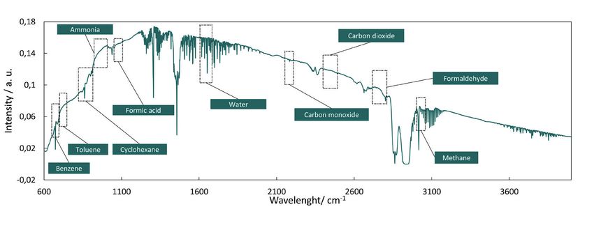
Hydrogen REPORTS
the field of LOHC is based on different LOHC substances.
The most technically advanced concept, which is pur-
sued by Hydrogenious Technologies, is based on the use
of the common heat transfer oil dibenzyltoluene, which
is available in large quantities and is not classified as a
dangerous good. As shown in Figure 1, hydrogen chemi-
cally bound to the molecule by saturation of the aromatic
rings in the hydrogenation.
Compared to other technologies that store hydrogen
at temperatures of -253 °C or at pressures up to 500 bar,
using LOHC technology greatly reduces the cost of han-
dling hydrogen. Transport and storage costs account for Figure 1: Concept of the LOHC-cycle for the storage and release of hydrogen
up to 70 % of the total cost of hydrogen supply using tra-
ditional high pressure or cryogenic hydrogen storage
technologies. Storing hydrogen in LOHC can increase
transport capacities by a factor of five, which reduces
transport costs by up to 80 %. An overview of the storage
densities of common hydrogen storage technologies is
shown in Figure 2.
Future operation of central LOHC hydrogenation
plants are possible at locations where a large amount of
by-product hydrogen is produced. The hydrogen-rich
or loaded LOHC (LOHC+) can be transported via stand-
ard tank trucks to the hydrogen refueling stations, which
are equipped with a dehydrogenation system (Release-
BOX). There, the hydrogen can be produced as needed Figure 2: Hydrogen densities as a function of pressure and temperature.
and then integrated into the existing hydrogen refu- Marking common areas for common hydrogen storage technologies
eling station technology. The German Climate Action (LOHC – green, compressed small "gaseaous" hydrogen (CGH2) – red, liq-
Plan of 2050 acknowledges that LOHC technology has uid hydrogen (LH2) – blue, compressed cryogenic hydrogen (CcH2) - vio-
considerable potential for establishing hydrogen as a lett)
fuel [2].
Table 1: Extract from the ISO FDIS 14687-2. Summary of maximum
3. HYDROGEN FOR FUEL CELL VEHICLES allowed contaminants in hydrogen for use as fuel for FCEVs [4]
Contamination chem. formular Maximum concentration
The purity of the hydrogen at hydrogen refueling stations Water H2O 5 ppmV
is specified by the international standard ISO-14687-2. In
Hydrocarbons CYHx (CH4 -Basis) 2 ppmV
the year 2004 this new standard was elaborated by the
Oxygen O2 5 ppmV
committee 197 and was valid for fuel cells vehicles as well
as for vehicles with a combustion engine. This is why in Helium He 300 ppmV
particular CO and sulfur limits were insufficient for FCEVs. Nitrogen / Argon N2 /Ar 100 ppmV
The limits were selected very strictly as the major priority Carbon dioxide CO2 2 ppmV
was given to the optimization of the lifetime of fuel cells. Carbon monoxide CO 0.2 ppmV
They were based on an initial list of permissible contami-
Sulphurous substances H2S, COS, CS2, etc. 0.004 ppmV
nants, which was created by the Canadian Fuel Cell Part-
Formaldehyde HCHO 0.01 ppmV
nership in 2003. The work of the Technical Committee
197 finally resulted in 2008 in a technical standard and Formic acid HCOOH 0.2 ppmV
ended in 2012 in the international standard ISO-14687-2. Ammonia NH3 0.1 ppmV
At a national level, SAE developed the SAE J2719 standard Halogenated substances HCl, HBr, Cl2, etc. 0.05 ppmV
in the USA, which is harmonized most widely with the Particles – 1 ppmW
standard ISO-14687-2. At present, this standard is under Total Contamination 300 ppmV
revision due to its conservative approach. New research
Required H2-purity 99.97 %
results will be taken into account (for example, that of the
DoE (U.S. Department of Energy) [3]). These research Purity 3.7
results include for instance explicit degeneration effects
Issue 1/2019 gas for energy 3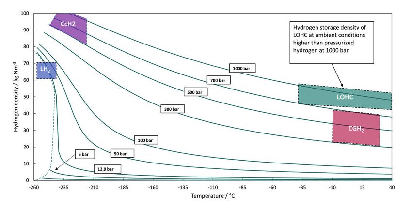
REPORTS               Hydrogen

                        of individual impurities or the economic consequences              This is the reason why the National Innovation Pro-
                        of ultra-high purification.                                    gram Hydrogen and Fuel Cell Technology funded the
                            Regardless of some likely changes of the permitted         Hy-Lab project since 2017 for 2.5 years with € 3.08 million.
                        limits in the near future, the results shown below demon-      In the Hy-Lab project, the institutes ZBT (Zentrum für
                        strate that even today, hydrogen from LOHC dehydroge-          Brennstoffzellentechnik Duisburg) and ZSW (Zentrum für
                        nation is suitable for the operation of PEM fuel cells. The    Sonnenenergie- und Wasserstoff-Forschung Baden-
                        example of some of the main components demonstrates            Württemberg) have committed themselves to the devel-
                        that the strict limits of ISO-14687-2 are kept.                opment of an independent laboratory for hydrogen qual-
                                                                                       ity measurement according to international standards.
                        4. ANALYSIS FOR DETERMINING THE                                The project will be carried out in close cooperation with
                        QUALITY OF HYDROGEN                                            NOW (Nationale Organisation Wasserstoff- und Brennst-
                                                                                       offzellentechnologie). This funded project alone shows
                        In addition to the actual compliance with the limits set by    the importance of a qualified analysis.
                        ISO and SAE for contaminations in hydrogen for use in              Even if there are opportunities in the future for hydro-
                        fuel cell vehicles, even the analysis of these impurities is   gen to be completely analysed according to ISO in inde-
                        an extraordinary challenge. The analysis of individual sub-    pendent laboratories, quality assurance is required within
                        stances requires a variety of different measurement prin-      the LOHC process. In order to rule out possible risks of
                        ciples. The ASTM (American Society for Testing and Mate-       contamination through sampling, Hydrogenious Tech-
                        rial) has already proposed and standardized methods for        nologies has established an In-Line-Analysis tailored to
                        analyzing a majority of the substances. Nonetheless, a         the expected impurities. With the H2-Quality-Module it is
                        holistic determination of all impurities is complex. Fur-      possible to quantify the most important impurities from
                        thermore, samplings of hydrogen show considerable              the LOHC process. The H2-Quality-Module can be cou-
                        sources of error.                                              pled as a mobile unit to any existing hydrogen release

 Figure 3: Pro-
 cess Flow Dia-
     gram of the
     H2-Quality-
   Module from
  Hydrogenious
   Technologies
 with FTIR, NIR,
    PID and dew
    point sensor

  Figure 4: FTIR
 spectrum of the
   LOHC product
  hydrogen with
the labeled spe-
  cific bands for
 detection of the
       impurities

                    4    gas for energy   Issue 1/2019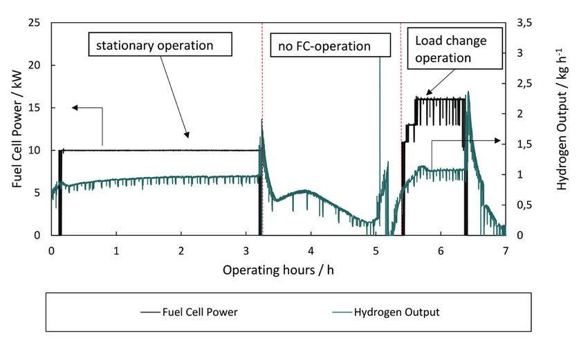
Hydrogen REPORTS
unit to measure contaminants in the hydrogen stream. be detected from 0 to 1000 ppmV, at a resolution of 1
Figure 3 shows a process flow diagram of the H2-Quality- ppmV.
Module. The analysis techniques used are briefly pre-
sented below. 4.4 Fourier Transform Spectrometer (FTIR)
4.1 Photo-Ionization Detector (PID) A versatile measuring principle for the quality control of
hydrogen for fuel cells is the FTIR spectrometry. For many
Photo-Ionization detectors are often used as field meters substances that are limited in hydrogen according to ISO-
for TOC (Total Organic Carbon) measurement. In the PID 14687-2, ASTM has already standardized FTIR-based test
sensor typically UV lamps are used, which excite and ion- methods.
ize the gas sample in a sample chamber. The released The operation of the FTIR is based on the Fourier
electrons flow in the process via a collecting electrode. transformation of a recorded interferogram. The inter-
The result is a measurable current that corresponds to a ferogram is generated by interferences of a splitted HeNe
concentration. laser beam, which passed through the sample. The first
The sensor Hydrogenious Technologies uses is a part of the laser passes a solid mirror and the examined
krypton lamp with an ionization energy of 10.6 eV. Mole- sample to the detector. The other part of the beam is
cules with a higher ionization energy are not detected. reflected on a moving mirror and then passes the sam-
These include the main air components as well as meth- ple. Each wavelength of the radiation spectrum interferes
ane, which has an ionization energy of 13.3 eV. Methane individually, resulting in a characteristic interferogram.
can be proven with other measuring principles (see From these, Fourier transformation can be used to calcu-
below). late the spectrum over the entire wavelength range.
The detection limit of the PID sensor is 1 ppb. The Since the various components in a gas mixture at differ-
photoionization detector is excellently suited to quantify ent wavelengths absorb radiation, the substances can be
the totality of hydrocarbons in the gas, with the excep- clearly assigned.
tion of methane. However, the composition of the hydro- Hydrogenious Technologies uses a spectrometer
carbons should be as constant as possible, since the equipped with a 5 m gas cell for extra precise measure-
response factors of the individual substances may differ ments. By using the PNNL (Pacific Northwest National
from one another. Laboratory) library, it is also possible to measure all sub-
stances contained in the PNNL without additional calibra-
4.2 Impedance Dew Point Sensor tion. Due to the high number of reference spectra, it is
also possible to fit overlays of individual components and
To determine the moisture in gases, so-called dew point thus increase the accuracy. Table 2 lists the detection
sensors are often used. Most of them are designed as a
mirror dew point sensor. Disadvantage of this measuring
principle is the cross sensitivity to all other condensable
substances. For this reason, a ceramic impedance dew
Table 2: Detection limits of the used FTIR compared to the limits of the ISO
point sensor is used.
14687-2 for selected substances
The sensor is based on the measurement of a resist-
ance between two DC electrodes. A hygroscopic but Substance Limits ISO FDIS Detection limit FTIR (ppmV)
non-conductive layer separates these two electrodes. By 14687-2 (ppmV)
adsorption of water, the resistance of the ceramic layer Ammonia 0.10 0.08
changes, which is translated into a water concentration in CO 0.20 0.16
the gas. The advantage of this sensor is that it is almost CO2 2.00 0.02
insensitive to other substances and reacts quickly. The Formalde- 0.01 0.08
moisture sensor used by Hydrogenious has a measuring hyde
range of 0.01 - 23,000 ppmV. Formic Acid 0.20 0.03
Hydrocarbons 2.00 0.1 -1 depending on single
4.3 Near-Infrared-Spectroscopy (N-IR) compounds
Methane 0.10 0.15
The Near-Infrared-Spectroscopy is based on the princi-
Water 5.00 0.22
ple of vibrational spectroscopy in which the normal
vibrations of the molecules are excited by electromag- Hologenated 0.05 Different, depending on single
compounds compounds
netic radiation in the wavenumber range between 4,000
and 13,000 cm-1. By this method, CO, CO2 and CH4 can
Issue 1/2019 gas for energy 5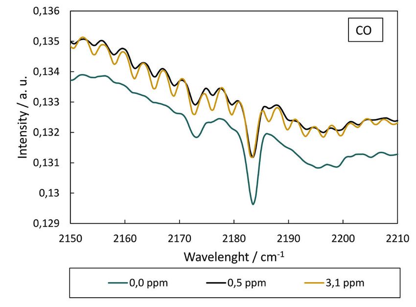
REPORTS            Hydrogen

                    limits of selected substances and the maximum allowed          the site of production. Hydrogenious Technologies uses
                    concentration of these according to ISO 14687-2.               control methods to determine if and to what extent
                                                                                   hydrogen needs to be purified from the LOHC process.
                    5. HYDROGEN FROM LOHC                                          For this purpose, raw gas, which leaves the dehydrogena-
                    DEHYDROGENATION                                                tion reactor without further purification steps, was exam-
                                                                                   ined. On this basis, further process stages are designed to
                    Crucial for the suitability of the LOHC concept for the sup-   obtain hydrogen in fuel cell quality.
                    ply of filling stations is the hydrogen quality. Whereas in
                    other storage technologies the question of hydrogen            5.1 Composition of the crude gas exiting the
                    quality is usually addressed at the hydrogen source loca-      dehydrogenation reactor
                    tion, in the case of storage in LOHC it becomes relevant at
                    the site of the application. For example, hydrogen pro-        Because the release of hydrogen from LOHC occurs in a
                    duced by steam methane reforming is purified directly at       catalyzed chemical reaction at elevated temperature,
                                                                                   issues such as selectivity, phase equilibria, and solubility
                                                                                   play a key role in hydrogen quality. Since the LOHC is a
                                                                                   liquid hydrocarbon, the study mainly focuses on the
                                                                                   evaporation of the carrier molecule in the gas phase and
                                                                                   their possible chemical conversion into by-products. The
                                                                                   influence of impurities in the air as well as those from the
                                                                                   technical LOHC production was also investigated. For
                                                                                   these reasons, one focused explicitly on TOCs, CO, CO2
                                                                                   and H2O for the investigation of gas purity.
                                                                                       The experiments were carried out in a continuous
                                                                                   laboratory dehydrogenation reactor, to which the above-
                                                                                   described H2-Quality-module for measuring the quality
                                                                                   of hydrogen was connected. The laboratory dehydroge-
                                                                                   nation unit consists of a heated tube filled with catalyst.
                                                                                   After a phase separation of LOHC and hydrogen, only
                                                                                   passive cooling to about room temperature takes place.
                                                                                   No further purification steps are switched between reac-
                                                                                   tor and H2-Quality-module. Figure 4 shows an example
                                                                                   of the FTIR analysis.
Figure 5: FTIR-spectra from LOHC dehydrogenation for analysis of CO                    The reaction parameters such as pressure, tempera-
content in hydrogen. Black – low LOHC-flow, yellow – high LOHC-flow,               ture and residence time of the LOHC in the reactor have
green – reference                                                                  to be adjusted correctly in order to achieve an optimum
                                                                                   raw gas quality. This is in close interaction with the choice
                                                                                   of the dehydrogenation catalyst.
                                                                                       The following considerations initially relate to a LOHC
                                                                                   material, which has been previously hydrogenated but
                                                                                   has not yet undergone further cycles of dehydrogenation
                                                                                   and hydrogenation. As will be seen later, the purity of the
                                                                                   released hydrogen improves significantly at higher cycle
                                                                                   numbers. This is an indication that the impurities initially
                                                                                   found to a considerable extent do not originate from the
                                                                                   reaction, but were already solved in the LOHC from the
                                                                                   beginning.
                                                                                       Most of the impurities in the hydrogen are hydrocar-
                                                                                   bon compounds. Since the dehydrogenation takes place
                                                                                   at about 300 °C, it can be assumed that the hydrogen at
                                                                                   the end of the reactor is saturated with those hydrocar-
                                                                                   bons, which pass into the gas phase at these temperatures.
Figure 6: Reduction of hydrocarbon compounds (TOCs) in hydrogen with               By cooling the gas stream, this amount is indeed signifi-
increasing LOHC-Cycle-Number measured with a PID sensor                            cantly reduced, nevertheless traces remain in the hydro-
                                                                                   gen. The determined concentration is at a single dehydro-

                6    gas for energy   Issue 1/2019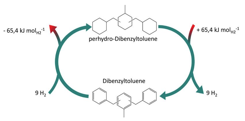
Hydrogen REPORTS
genation of the loaded LOHCs at about 400 ppmV. Hydro- a reduction of hydrocarbons in the product gas by
carbons ultimately act very differently on fuel cells, for 72.5 %, compared to the reference experiment, was
example, methane behaves inertly on the anode side, found.
but reduces the stack performance through steady accu- The contamination with carbon monoxide, which is
mulation. On the other hand, aromatics adsorb on the harmful to fuel cells, was reduced completely by 100 %.
anode side and block the adsorption sites for hydrogen The amount in the gas stream was reduced from 3.1
In addition to the TOCs, which are mainly found due ppmV to 0.0 ppmV after recycling the material. Thus, a
to evaporation of the LOHC carrier material, water was degradation of the catalytic fuel cell membrane by CO in
measured with proportions up to 300 ppmV. Water is sol- LOHC hydrogen is excluded after only a few cycles.
uble in small amounts in LOHC, Aslam et al. [5] found a These experiments support the thesis that most of
solubility of 1000 ppm in the hydrogenated LOHC and the contaminants in LOHC-hydrogen come from dis-
9000 ppm in the dehydrogenated LOHC. During long- solved substances in the carrier medium. The continuous
term storage, the carrier material saturates by air humid- cycle of hydrogenation and dehydrogenation signifi-
ity. The dissolved water can ultimately be recovered in cantly increases the quality of the raw gas. In combina-
hydrogen. A suitable storage and tank concept can mini- tion with a storage and tank concept with moisture and
mize this influence. Water behaves inertly in the fuel cell, air exclusion, the quality can be increased even further.
but the concentrations must be kept low to avoid the Since crude hydrogen does not meet the ISO standard
formation of ice in the fuel cell system.
Carbon dioxide is largely inert in the fuel cell. CO2 low-
ers the hydrogen concentration on the anode side just
like CH4. After dehydrogenation of LOHC+, a maximum of
5 ppm of CO2 was detected in the hydrogen. Similar to
water, carbon dioxide comes mainly from ambient air. It is
still unclear whether CO2 forms small amounts of CO in
the fuel cell by reverse water gas shift reaction.
Carbon monoxide, unlike CO2, has been shown to be
harmful to fuel cells. Carbon monoxide strongly adsorbs
to the platinum-based catalytic materials and blocks
these hydrogen adsorption sites needed for dissociation.
CO was measured only in „virgin“ LOHC with a low num-
ber of cycles in small amounts in LOHC-hydrogen. The
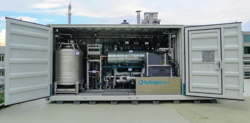
measured carbon monoxide content increased signifi- Figure 7: ReleaseBox HD1011 from Hydrogenious Technologies at the
cantly as a function of increasing LOHC feed flow in the Fraunhofer IAO for generating electricity from LOHC hydrogen by means
reactor, which is shown in Figure 5. This indicates that of a fuel cell for feeding into a smart grid
carbon monoxide originates from the LOHC and does
not come from the reaction itself. With a measured maxi-
mum of 3.1 ppmV CO for LOHC material which is dehy-
drogenated for the first time, this value significantly
exceeds the limit of 0.2 ppmV by ISO 14687-2.
Formic acid, ammonia formaldehyde and hydrogen
sulfide were never detected in the experiments.
Experiments with recycled material have demon-
strated the influence of dissolved impurities in LOHC on
hydrogen quality. In a closed autoclave, LOHC was hydro-
genated and dehydrated in a semi-batch mode for sev-
eral cycles. The carrier medium at no time had contact
with the air atmosphere. During each test, the gas quality
was measured. Figure 6 shows the strongly decreasing
course of the TOCs in the gas stream over the number of
cycles. The proportion of TOCs decreases by more than
60 % within 15 cycles, with a reduction of 50 % already
after the first 4 cycles. The 15-fold recycled material was Figure 8: Measurement data for fuel cell operation with LOHC-hydrogen
then fed directly, without storage, to a continuous dehy- on the ReleaseBox HD1011 at the Fraunhofer IAO in Stuttgart
drogenation as described above. In this experiment, even
Issue 1/2019 gas for energy 7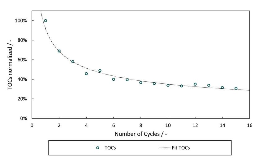
REPORTS       Hydrogen

          completely (especially during the first few cycles), further    reactor without further purification contains mainly
          purification methods are required.                              hydrocarbon impurities. If LOHC undergoes the hydro-
                                                                          genation and dehydrogenation cycle several times, as is
          5.2 Pure LOHC hydrogen in fuel cell quality                     the case in the life cycle of the LOHC anyway, these con-
                                                                          taminants can be reduced to about 110 ppmV. The traces
          To operate fuel cells, the remaining impurities have to be      of CO that vanish after only a few cycles anyway, as well
          removed from the raw gas. In addition to state-of-the-art       as the remaining hydrocarbons in the crude gas, can be
          techniques such as simple activated carbon filtration or        filtered out by means of adsorption in simple activated
          pressure swing adsorption, as used in steam reforming,          carbon filters or in pressure swing adsorption plants.
          new concepts such as membrane filtration using the pal-         Thus, the LOHC technology, with its advantages of high
          ladium membrane are also being investigated at Hydro-           storage density and easy handling, delivers hydrogen for
          genious Technologies. However, as shown below, hydro-           fuel cells reliably.
          gen can already be produced in fuel cell quality with
          simple activated carbon filtration.                             THANKS
              The ReleaseBox HD1011 (Figure 7) is Hydrogenious
          Technologies first demonstration plant on an industrial         We would like to thank Florian Klausmann from the
          scale. The system delivers up to 3 kgH2 h-1 and is inte-        Fraunhofer IAO for providing the Smart Grid data. Further
          grated into the Smart Grid of the Fraunhofer IOA in Stutt-      information on the Smart Grid of the Fraunhofer IAO:
          gart. A PEM fuel cell with a nominal power of 25 kWel           www.microsmartgrid.de
          produces electricity from the hydrogen sored with LOHC.
              To separate the impurities contained in the raw gas, a      REFERENCES
          dry-adsorber-bed is used. A combination of activated
          carbon and metal oxide adsorber materials separates             [1] H2.LIVE Wasserstofftankstellen in Deutschland &
          hydrogen from hydrocarbons, as well as CO and CO2, to               Europa. Abgerufen am: 20.07.2018 https://h2.live/
          achieve fuel cell quality. After the adsorber bed, 0.1 ppm      [2] Bundesministerium für Umwelt, Naturschutz, Bau
          of hydrocarbons in the hydrogen stream were measured                und Reaktorsicherheit. „Klimaschutzplan 2050 – Kli-
          with the PID detector. In addition, no more CO could be             mapolitische Grundsätze und Ziele der Bundesre-
          detected in the exhaust by means of FTIR. Thus, the gas             gierung.“ (2016), S.54
          flow reaches fuel cell quality, as it is required at hydrogen   [3] Ohi, J. M., et al. „Hydrogen fuel quality specifications
          refueling stations. The cleaning according to the adsorp-           for polymer electrolyte fuel cells in road vehicles.“ US
          tion principle is suitable to eliminate hydrocarbons and            DOE EERE (2016).
          carbon monoxide almost completely. Figure 8 shows               [4] ISO 14687-2:2012: Hydrogen fuel – product specifica-
          the operation of the fuel cell of the ReleaseBox HD1011 at          tion – part 2: proton exchange membrane (PEM) fuel
          the Fraunhofer IOA in Stuttgart. Both, a stationary opera-          cell applications for road vehicles. Hrsg. von Interna-
          tion at the first operating point and a dynamic load                tional Organization for Standardization Ausg. 2012
          change operation of the fuel cell can be easily operated        [5] Rabya, A.; Karsten Mü ller, K .and Arlt, W.: “Experimen-
          without loss of performance of the fuel cell.                       tal study of solubility of water in liquid organic hydro-
              Hydrogenious Technologies will pursue further work              gen carriers.” Journal of Chemical & Engineering
          on the evaluation of various purification concepts as well          Data 60.7 (2015): 1997-2002
          as the establishment of additional analytics at in order to
          prove the quality requirements of ISO-14687-2 in more
          detail in the future.

          6. CONCLUSION
                                                                                          AUTHOR
          Due to its good transportability and easy handling, LOHC
          is ideally suited as a hydrogen mass storage system at                          Dipl.-Ing. Alexander Seidel
          hydrogen refueling stations. With LOHC, 57 kg of hydro-                         Hydrogenious Technologies GmbH |
          gen per m³ of LOHC can be stored. Since the release of                          Tel: +49 9131 12640 252 |
          hydrogen requires a chemically catalytic reaction, the                          alexander.seidel@hydrogenious.net
          question of hydrogen purity is particularly important. The
          limit values specified in ISO 14687-2 are already achieved
          for the main components with simple purification steps.
          The so-called crude H2 that is obtained directly after the

     8     gas for energy   Issue 1/2019
You can also read