Research on importing production information into Manufacturing Execution System of Precast Concrete factory based on Building Information ...
←
→
Page content transcription
If your browser does not render page correctly, please read the page content below
E3S Web of Conferences 276, 02009 (2021)                                                       https://doi.org/10.1051/e3sconf/202127602009
WCHBE 2021

    Research on importing production information into
    Manufacturing Execution System of Precast Concrete factory
    based on Building Information Modeling
    Zhenlei Guo1,*, Feihua YANG1, Jiayang Zhang1, and Weixuan Zhao1
    1Academy   of Green Building Technology, Beijing Building Materials Academy of Sciences Research, Beijing 100041, China

                 Abstract. Building Information Modeling in Precast Concrete factory should consider the split design and
                 production as a whole, so we should pay attention to import the production information into MES and achieve
                 enterprise level application. This paper studied two methods of importing production information to
                 Manufacturing Execution System, namely DXF drawing and U file. This paper studied how to match
                 information of DXF drawing with MES’s layer, text information and title bar. This paper also studied the
                 correct format of U file and the information that can be resolved by MES. The feasibility of this two methods
                 was verified through the prefabricated building project "Jin-an Hong Bao 7#", and the types of prefabricated
                 components, information quality, efficiency and cost of the two methods are compared. Dxf drawing is able to
                 cover all kinds of precast components, easy for new comers to master, but the drawing efficiency is low.
                 Currently, U file only supports composite floor slab, and it has a long training period, but it also has extremely
                 low error rate and extremely high drawing efficiency.PC factory should continue to improve u file, which can
                 greatly improve work efficiency and reduce engineering errors.

  1 Introduction                                                         deepening & production applications nor effective
                                                                         technical measures for importing production information
  Prefabricated building has advantages such as high                     into MES.
  construction efficiency, low energy consumption and low                    To promote coordinated development of intelligent
  environmental impact [1]. In 2016, General Office of the               construction and building industrialization, thirteen
  State Council of the People's Republic of China clearly                departments including Ministry of Housing and
  proposed to vigorously develop prefabricated building                  Urban-Rural Development and National Development
  and make prefabricated building account for 30% of the                 and Reform Commission issued the following proposal
  floor area of new buildings within around 10 years [2].                jointly: Accelerate digital and intelligent upgrade of
  With prefabricated building’s gradual stepping on the                  component production to realize less-manned and even
  right track, numerous architectural design, construction               unmanned factories. Accelerate the application of
  enterprises, etc. have entered precast concrete (PC) field,            technologies such as intelligent human-computer
  which sets off a craze for PC factory investment &                     interaction, intelligent logistics management, additive
  development nationwide, driving the rapid development                  manufacturing as well as intelligent equipment [6].
  of the PC market [3].                                                      To promote digital and intelligent upgrade of the
      Building information model (BIM) is digital                        production of PC factory, it is necessary to realize
  expression of physical characteristics and functional                  digitization and intellectualization from the source, i.e.
  characteristics of construction works. It not only                     detailed design drawing needs to be imported into the
  eliminates information transmission barriers, but also                 production equipment. This paper studies two effective
  provides a 3D visual management platform that can be                   methods for importing production information into MES,
  used for data interaction [4].                                         namely, drawing Dxf drawing and preparing U file.
      Theoretically, BIM technology is able to integrate
  various relevant information and data models from
  building design, production, construction, operation and               2 Drawing Dxf Drawing
  maintenance. In addition, it is also able to realize effective
                                                                         Dxf (Drawing Exchange Format) is a file format
  transmission and sharing of data among different project
                                                                         developed by Autodesk for CAD data exchange between
  stages and departments [5]. However, in fact, despite there
                                                                         Auto CAD and other software [7], and it needs to be drawn
  are certain research and practice on the BIM technology
                                                                         manually.
  of PC factory at present, they are basically staying in
                                                                            Since MES imports precast component information by
  deepening and demonstration level with neither overall
                                                                         analyzing the layer information of the graphics and text in

    *
        Zhenlei Guo: 424285621@qq.com
© The Authors, published by EDP Sciences. This is an open access article distributed under the terms of the Creative Commons Attribution
License 4.0 (http://creativecommons.org/licenses/by/4.0/).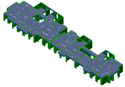
E3S Web of Conferences 276, 02009 (2021)                                                  https://doi.org/10.1051/e3sconf/202127602009
WCHBE 2021

   Dxf drawings, it is necessary to assign clear layer                  situation. Uniform          text    layer     property      is
   properties to all graphics and text in drawings, and such            PUB_PMSTEXT.
   properties shall not be crossed.

   2.1 Graphic Information
   Precast component needs to be subject to detailed design
   based on the construction requirements proposed for
   precast component from multiple disciplines, production                           Fig. 1 Format of Uniform Title Bar
   process requirements for factory components and                         Drawing type: “1” represents component drawing,
   construction & lifting requirements [8].                             and “2” represents rebar drawing. The filling rules of
       A detailed drawing of a precast component includes               component type are as follows:
   information such as outer contour of component, rebar,                  B = "B”; //1 floor slab
   truss, embedded part, sleeve, door & window, reserved                   DLB = "DLB”; //1 floor slab (composite floor slab)
   hole, label, title bar, rebar list and embedded part list.              WB = "WB"; //2 roof slab
       It is required to clear layer properties and their                  KB = "KB"; //3 hollow slab
   purposes (Table 1) based on the requirements for layer                  CB = "CB"; //4 groove-shaped slab
   properties from MES, and strictly follow Table 1 when                   ZB = "ZB"; //5 folded plate
   drawing Dxf drawings. According to comparative study,                   MB = "MB"; //6 multi-ribbed plate
   overlapped lines are not allowed. Otherwise, an error will              TB = "TB"; //7 stair tread
   be reported by the program in MES analysis, and the                     GB = "GB"; //8 (ditch) cover plate
   equipment cannot operate normally.                                      QB = "QB"; //9 wallboard
                                                                           TGB = "TGB”; //10 gutter board
          Table 1 Dxf Layer Properties and their Purposes                  D = "D"; //11 floor
         Layer                                                             W = "W”; //12 fence board
                                       Purposes
       Properties
                        Outer contour of component after primary
                                                                           L = "L”; //13 beam
       PC_Shape                                                            WL = "WL"; //14 roof beam
                                        spreading
       PC_Shape2
                       Outer contour of component after secondary          DL = "DL”; //15 crane beam
                                        spreading                          QL = "QL"; //16 ring beam
          Bar                      Rebar arrangement                       GL = "GL"; //17 lintel
         Truss                        Truss contour
         Door1                      Layer of 1# door                       LL = "LL”; //18 linking beam
         Door2                      Layer of 2# door                       JL = "JL”; //19 foundation beam
       Window1                     Layer of 1# window                      TL = "TL"; //20 stair beam
       Window2                     Layer of 2# window                      LT = "LT”; //21 purline
       Defpoints                  Labeling datum point                     Z = "Z”; //22 column
      DIM_LEAD                         Callout line
       Bar_TAB                          Rebar list
                                                                           J = "J”; //23 foundation
        PC_Part                  Layer of embedded part                    ZH = "ZH”; //24 pile
       Title bar             Title bar wireframe of drawing                T = "T”; //25 stair
      Embed_TAB                   List of embedded part                    YT = "YT”; //26 balcony
        Electric        Reservation and embedment of electrical            M = "M”; //27 embedded part
       appliance                         appliance
      Tapping and
                           Reserved hole and reserved sleeve
         sleeve
                                                                        3 Preparing U File
   2.2 Text Message                                                     As an intermediate file developed by German Unitechnik
                                                                        Company for data exchange with automation equipment,
   Prefabricated building drawing includes split & detailed             U file provides production with various working files and
   design specification of component, project split plan,               information [10].
   detail of project assembling nodes, detail of project wall               According to research, U file is composed of a fixed
   structure, project BOQ, structural detail of component,              writing format and includes precast component type,
   node detail of component, lifting detail of component and            boundary dimensions, rebar arrangement and sleeve
   burying detail of embedded part of component [9].                    information. The precast component information
        The split & detailed drawing of a precast component             contained in U file can be read through MES analysis.
   includes information such as component name,                         Since there are strict requirements for the writing format
   component drawing No., drawing type, concrete grade,                 of U file, it is inconvenient to be written manually, so it is
   component type, concrete density, component weight,                  commonly used for software output.
   spreading amount and component thickness. Despite the                    The writing format is as follows:
   title bar formats of all design organizations are extremely              HEADER__ // Header record of the order
   non-uniform, they can be standardized as the following                   SLABDATE // Header record of the element part
   format (Fig. 1) for standardization purpose, or special title            CONTOUR_ // Header record of the contours
   bar can be customized by MES developer based on actual                   CUTOUT_ // Header record for cutouts
                                                                            geomotric date // Geomotric date

                                                                    2
E3S Web of Conferences 276, 02009 (2021) https://doi.org/10.1051/e3sconf/202127602009
WCHBE 2021
MOUNPART // Header record for mounting parts
geomotric date // Geomotric date
RODSTOCK // Header record for rod stock
mounting date // Individual mounting parts
BRGIRDER // Header record for braced girders
rodstock date // Individual rodstock bars
REFORCEM // Reinforcement
braced girder date // Individual braced girders
END // End
4 Prefabricated Project - 7# Building of
Red Fort Lan Palace
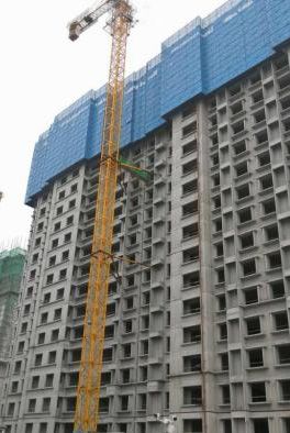
Taking Red Fort Lan Palace Project, Tangshan City,
Hebei Province as an example (Fig. 2), 7# building of this
project has the gross aboveground floor area of 17,723.58
m2, and its precast components include 112 kinds of
composite floor slabs and 4 kinds of prefabricated stairs.
There is no vertical precast component. The assembly rate Fig. 3 Flow Chart for Drawing of Dxf Drawing
is 51%. Precast component information was imported to
MES by means of Dxf drawing and U file.
4.2 Preparing U File of 7# Building of Red Fort
Lan Palace
For preparing of a U file (Fig. 4), it is necessary to
establish a PC model at first, and then, perform splitting,
rebar arrangement, reservation and embedment based on
design drawing, rebar drawing, M&E drawing, refined
decoration drawing and construction requirements.
Finally, U file shall be prepared directly with software
(Fig. 5).
Fig. 2 Prefabricated Project - 7# Building of Red Fort Lan
Palace
4.1 Drawing Dxf Drawing of 7# Building of Red
Fort Lan Palace
For drawing of Dxf drawing, it is necessary to draw the
contour of the precast component be referring to the
structural drawing (Fig. 3) at first, and arrange rebar
based on rebar drawing. Besides, overall consideration
shall be made for reservation and embedment of
disciplines such as building, structure, water, heating,
electric, refined decoration and construction. Next, layer
properties need to be matched based on Dxf requirements.
Afterwards, factory production can be performed after
successful MES analysis. Fig. 4 Flow Chart for Preparing of U File
Fig. 5 PC Model, Detailed Design and Generation of U File
3E3S Web of Conferences 276, 02009 (2021) https://doi.org/10.1051/e3sconf/202127602009
WCHBE 2021
5 Comparison of Two Methods PC factory should continue to improve u file, which
can greatly improve work efficiency and reduce
engineering errors.
5.1 Comparison of Components Covered
Any kinds of precast components, including composite References
floor slab and prefabricated stair can be drawn with Dxf
drawing. However, only composite floor slab is covered 1. XiaoKun Huang, ChunYu Tian, MoLin Wan.
by U file, and no other precast components are supported. Researches and applicationgs of precast concrete
Currently, prefabricated stair is manufactured by fixed strutres in China. J. Building Science, (2018)
die table with low informatization degree. For 2. General Office of the State Council.Guiding opinions
manufacturing of prefabricated wall, the types of precast of the general office of the State Council on
components covered by U file are apparently inadequate. vigorously developing prefabricated buildings.
000014349/2016-00194.EB. ISC〔2016〕71
5.2 Comparison of Information Quality 3. CY331.Analysis on the development status and
market prospect of China's PC component industry in
Repeated and redundant lines are easy to occur when Dxf 2020. www.chyxx.com
drawing is applied. According to the statistics, there are 3
kinds of invalid floor slabs in 112 kinds of prefabricated 4. Da Jiang.Integrated applicationg of BIM technology
floor slabs. If U file is used, the equipment needs to be in prefabricated building. J. Building
commissioned at the first time, but there will be no quality Structiong ,24(2019).
problem during operation. 5. Peng Gao, Jie Wang, JieYing Wu. BIM based design
of a prefabricated concrete frame structure and
analysis of key problems . J. Building
5.3 Efficiency Comparison
structure,S2(2019)
When Dxf drawing is applied, drawing of floor slab 6. Ministry of housing and urban rural development,
contour, rebar arrangement, truss position, opening rebar national development and Reform Commission,
avoidance, reservation & embedment and verification are Ministry of science and technology.Guiding opinions
necessary with the drawing efficiency of 7 - 10 of the Ministry of housing and urban rural
drawings/person/day and the total working hours of 20 development and other departments on promoting the
personsꞏday. When U file is applied, establishment of coordinated development of intelligent construction
model, floor slab splitting, rebar arrangement rules, and building industrialization
opening avoidance rules, reservation & embedment and 000013338/2020-00264. EB.〔2020〕60
verification are necessary with the drawing efficiency of 7. ShenHua Liu,WeiBing Xu.AutoCAD DXF file
20 - 40 drawings/person/day and the total working hours format and secondary development. J.Science &
of 10 personsꞏday. Technology Information,(2017)
8. ShaoNan Sun, BingBing Sun, JiaWei Wu. BIM
5.4 Training Cost based collaborative evaluation of prefabricated
building design stage. J. Yangtze River,04(2020)
If Dxf drawing is applied, CAD training with the period
≤5 days is necessary. If U file is applied, PC software 9. YaJiang Huang, Ying Dong, ZiChen Zhang.
training with the period ≥20 days is needed. Research on detailed design of prefabricated building
structure based on BIM Technology. J.Construction
Technology. S4(2018)
6. Conclusions 10. Unitechnik. Leitrechner Unicam
This paper introduced two methods for PC factory to link 10.www.unitechnik-c
with detailed design and production based on BIM
technology: Dxf drawing and U file. They have obvious
advantages and disadvantages: Dxf drawing is able to
cover all kinds of precast components, easy for new
comers to master, but the drawing efficiency is low.
Currently, U file only supports composite floor slab, and
it has a long training period, but it also has extremely low
error rate and extremely high drawing efficiency.
Despite U file only supports composite floor slab at
present, it will become an inevitable choice for realizing
automation and informatization along with the
development of the U files of prefabricated inner/outer
wall, prefabricated beam, prefabricated column and other
components.
4You can also read