Residential Multi-Dwelling Unit Cabling Guidelines - Building Industry Consulting Services (BICS)
←
→
Page content transcription
If your browser does not render page correctly, please read the page content below
Building Industry
                                      Consulting Services
                                                   (BICS)

               Residential Multi-Dwelling Unit
                    Cabling Guidelines

Page 1 of 22                                                2011-05-24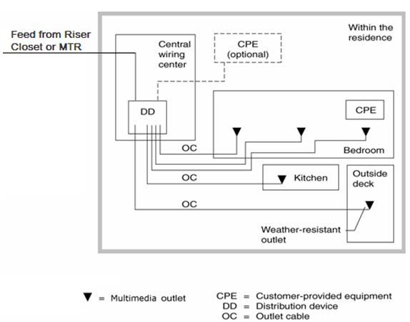
This document provides guidelines and recommendations for pre-wiring new Multi Dwelling Unit (MDU)
buildings with Ethernet cables (CAT-5e) during the construction stage, prior to the installation of drywall.
The guidelines are best used when combined with a Multi Media Cabinet, where all telecommunications
cabling comes together in the home.

                                                               Table of Contents
1.      Terms and Conditions of Use ........................................................................................................... 3
2.      Summary of Key Points ..................................................................................................................... 5
     2.1 In the Suite [see section 4.7 and 4.8 for details] ........................................................................... 5
     2.2 In the Floor closet (TR) [section 4.6] ................................................................................................ 5
     2.3 Floor Distribution [section 4.8.] ........................................................................................................ 5
     2.4 In the Main Equipment Room .......................................................................................................... 5
     2.5 In the Entrance Facility..................................................................................................................... 5
3.      Technical Guide - Introduction ......................................................................................................... 6
4.      Components........................................................................................................................................ 7
     4.1 Entrance Facility (EF)....................................................................................................................... 8
        4.1.1 Grounding ................................................................................................................................ 8
        4.1.2 Security and Access Provisions .............................................................................................. 8
        4.1.3 Easement ................................................................................................................................ 9
     4.2 Equipment Room (or Main Terminal Room) .................................................................................... 9
     4.3 Demarcation Point (DP) ................................................................................................................. 10
        4.3.1 Service Provider Demarcation Point ..................................................................................... 10
        4.3.2 Customer Demarcation Point ................................................................................................ 10
     4.4 Backbone Cabling .......................................................................................................................... 10
     4.5 Riser Systems ................................................................................................................................ 10
     4.6 Floor Closet or Telecoms Room (TR) ............................................................................................ 11
     4.7 Distribution Device ......................................................................................................................... 11
     4.8 Floor Distribution Systems (Horizontal Cabling) ............................................................................ 13
        4.8.1 Horizontal Cable Specification .............................................................................................. 13
        4.8.2 Outlet Cable (Horizontal Cable) ............................................................................................ 13
        4.8.3 Multimedia Outlets ................................................................................................................. 14
5.      Illustrations and Examples .............................................................................................................. 16
     5.1 Premises Cabling System .............................................................................................................. 16
     5.2 Apartment Building with a Central Backbone................................................................................. 17
     5.3 Seven Unit Townhouse .................................................................................................................. 18
     5.4 Side-By-Side Duplex-to be linked with ........................................................................................... 19
     5.5 Strata Developments - Strata Bare Land ....................................................................................... 19
6.      Testing MDU Installation, Cabling and Multimedia Outlets ......................................................... 20
     6.1 Test Equipment Recommendation ................................................................................................. 20
     6.2 Verification Tests – cable and multimedia outlets .......................................................................... 20
     6.3 In-suite Network Certification - Test Verification Check Sheet ...................................................... 21
     6.4 MDU 8-PIN Modular (RJ-45) Jack Terminating Instructions .......................................................... 22

List of Figures
Figure 1: EIA/TIA 568A Pin Assignments
Figure 2: Typical Residential Premises Cabling System (Logical View)
Figure 3: Backbone and Distribution Cabling Layout for an Apartment Building with a Central Backbone

Page 2 of 22                                                                                                                                 2011-05-24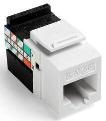
1. Terms and Conditions of Use

 (a)    Any installation of premise wire shall be in accordance with the laws, rules, regulations, technical
        standards and codes in effect at the time of installation, whether federal or provincial.

 (b)    The pre-wiring of a premise will have an immediate impact on the service to the premise as well it
        could affect the network system of TELUS. As a result TELUS advises that any design,
        installation and wiring are to be carried out by a trained telecommunication technician. All
        telecommunications technicians are to be trained and certified by the manufacturer and supplier
        of the product or equipment to be installed.

 (c)    This document makes references to and summaries of the rules as provided in the Canadian
        Electrical Code (CEC). The reference and summaries of these rules are provided for brevity and
        convenience. Prior to any design, installation or pre-wiring of a premise, every trained technician
        is to be familiar with the CEC.

 (d)    The CEC and the Provincial or Municipal Electrical Inspection Branch may require a permit prior
        to any pre-wiring, adding to, or rearranging the communications and data interior wiring. They
        may also require that the work be inspected upon completion. Contact your local (Provincial or
        Municipal) Electrical Inspection Branch for further information regarding these requirements. If
        outlets are to be located in exterior walls (or walls between suites) obtain advice on maintaining
        the integrity of the vapor barrier or fire-rated wall.

 (e)    While TELUS uses reasonable efforts to include accurate and up-to-date information in this
        Document your use of this Document is at your risk. Changes or updates to the contents of this
        Document may occur without notice to you.

 (f)    TELUS shall not be liable to the user, or any other person, for damages or loss of any kind or
        nature, including but not limited to injury or death resulting from the user’s or any other person’s
        unfamiliarity with the CEC, or any other laws or regulations applicable to pre-wiring or the
        installation of wires or cables, or for reliance by the user or any other person on the matters
        contained in this document.

 (g)    You hereby agree that you shall not use any information contained in this Document in any
        claims, proceedings, suits or actions against TELUS, its suppliers or affiliates. You may not post,
        publish, reproduce, transmit or otherwise distribute information or material from this document: (a)
        constituting or encouraging conduct that would constitute a criminal offence or give rise to civil
        liability; (b) which is protected by copyright, or other intellectual property right or derivative works
        thereof, without obtaining permission of the copyright holder; (c) otherwise use this Document in a
        way that is contrary to law or which would adversely impact use of this Document by other users
        including the posting or transmitting of other information.

 (h)    Neither TELUS, its suppliers, affiliates nor any other party involved in creating, producing, or
        delivering the Document is liable for any direct, indirect, incidental, special, consequential,
        punitive or other damages whatsoever including business interruption, loss of use, data,
        information, profits (regardless of the form of action, including but not limited to contract,
        negligence or other torturous act) arising out of or in connection with your use of the Document
        even if TELUS has been advised of or foresees the possibility of any damages occurring

Page 3 of 22                                                                                         2011-05-24
Without limiting the foregoing, everything in the Document is provided to you "AS IS" WITHOUT
REPRESENTATION, WARRANTY OR CONDITION OF ANY KIND, EITHER
EXPRESS,IMPLIED, OR STATUTORY INCLUDING, BUT NOT LIMITED TO, IMPLIED
REPRESENTATIONS, WARRANTIES OR CONDITIONS OF MERCHANTABILITY, FITNESS
FOR A PARTICULAR PURPOSE, DURABILITY, TITLE, OR NON-INFRINGEMENT OF
INTELLECTUAL PROPERTY RIGHTS.
(i) You agree to defend, indemnify and hold TELUS, its suppliers and affiliates harmless from any
and all liabilities, costs and expenses, including reasonable legal fees related to any violation of
these Terms and Conditions by you, or in connection with your use of this Document or with the
placement or transmission of any message or information from the Document by you.
(j) TELUS' failure to insist upon or enforce strict performance of any provision of these Terms and
Conditions shall not be construed as a waiver of any provision or rights contained in these Terms
and Conditions.
(k) By using this document, you agree that these Terms and Conditions shall be governed by the
laws of the residing province and the federal laws of Canada applicable therein and you agree to
be bound by the laws of these jurisdictions.
Page 4 of 22 2011-05-242. Summary of Key Points
2.1 In the Suite [see section 4.7 and 4.8 for details]
• Individual Cat-5e runs, 25mm (1") conduit, 90m maximum length.
• Room outlets include single 6-Pin Modular Jack (RJ-11) for Telephone.
• Room outlets include single 8-Pin Modular Jack (RJ-45) for Data & IPTV.
• Minimum install one outlet adjacent to each Cable-TV outlet for TTV
• 712mm x 368mm (28" X 14.5”) (minimum) recessed enclosure REQUIRED in closet/storage
room at reasonable working height 1219mm (48"), to terminate all in-suite wiring.
• 2 x duplex 15A un-switched power receptacles dedicated to TELUS and other Service
Provider’s equipment and installed within the designated enclosure.
• TELUS Media Hub installation notes [section 7.7]
2.2 In the Floor closet (TR) [section 4.6]
• Patch panel
2.3 Floor Distribution [section 4.8.]
• 25mm (1") conduit everywhere, minimum
2.4 In the Main Equipment Room
• Add EXTRA backboard space for POTS SPLITTER units [section 4.2]
2.5 In the Entrance Facility
• Protectors installed here [section 4.1]
• Grounding mandatory [section 4.1.1]
Page 5 of 22 2011-05-243. Technical Guide - Introduction This document outlines general guidelines regarding the components, design, and installation of the infrastructure for residential Multi-Dwelling Unit (MDU) structured cabling applications. The guidelines herein provide for a generic cabling system for current and developing basic, advanced, and multimedia telecommunications services. Within this document, the general guidelines are aligned with the principles and requirements of ANSI/TIA/EIA-570-A, Residential Telecommunications Cabling Standard, and CSA T525. This document makes frequent references to and summaries of the rules as provided in Section 60 of the Canadian Electrical Code (CEC). The references and summaries of these rules are provided for brevity and convenience. Prior to any design or installation of the infrastructure and equipment for MDU structured cabling, every person or vendor is advised to review the CEC. MDU outlet cabling consists of 4-pair twisted-pair cable(s) and associated connectors that meet or exceed the requirements for category 5e cabling. In addition, the MDU premises’ cabling is to be placed in a star topology with the length of each outlet cable not to exceed 90 m (295 ft). The 90 m (295 ft) length allows for an operational length of 100 m (328 ft) including patch cords or jumper wire and equipment cords. As a cabling system is an important part of a network system, TELUS strongly recommends an integrated end-to-end solution for all category 5e wiring cabling installations from approved manufacturers and suppliers. All structured cabling design, installation and work is to be performed by Vendors who are fully trained and certified in the design and installation of voice, data and imaging cabling systems. All Vendors are to be trained and certified by the manufacturer and supplier to install, test and work on their product. Page 6 of 22 2011-05-24
4. Components
The following sections, 4.1 to 4.7 outline the basic components used to provide telecommunications
services to residential MDUs. Illustrations and examples of typical cabling layouts are shown in Section 5.
The components and cabling installation for residential MDUs shall meet all the applicable requirements
of the latest issue of the following standards and specification documents below:
ANSI/TIA/EIA-568-B.1
ANSI/TIA/EIA-568-B.2
ANSI/TIA/EIA-568-B.3
ANSI/TIA/EIA-569 CSA-T530
ANSI/TIA/EIA-568-A CSA-T529
ANSI/TIA/EIA-606 CSA-T528
ANSI/TIA/EIA-607 CSA-T527
TIA/EIA TSB67
TIA/EIA TSB72
TIA/EIA TSB75
TIA/EIA TSB95
ISO/IEC 11801
ISO/IEC JTC 1/SC 25/WG 3 N598 (May 2000)
IEC 603-7
CENELEC EN50173
ANSI/ICEA S-90-661
ANSI/ICEA S-80-576
ANSI/ICEA S-83-596
ANSI/ICEA S-83-640
ANSI/EIA/TIA-492AAAA
ANSI/TIA/EIA-472CAAA
ANSI/TIA/EIA-472DAAA
ANSI/TIA/EIA-598
ANSI/TIA/EIA-455
ANSI/TIA/EIA-604
ANSI/TIA/EIA-570 CSA-T525
CSA C22.1-02 Canadian Electrical Code Part 1
Page 7 of 22 2011-05-244.1 Entrance Facility (EF)
The entrance facility consists of the telecommunications cable entrance to the building (EF), including the
entrance point (EP) through the building wall that contains the entrance cable to the building and
continuing to the main equipment room. The EF may contain the backbone pathways that link to other
buildings in campus situations. Antenna entrances may also be included as part of the EF. Primary
Protection devices including the primary protectors are located here.
The CEC applies to the installation of communications systems. The installation of communication
systems shall be in compliance with the CEC. Rule 60-200 of section 60 of the CEC requires that:
a) a primary protector shall be provided on each electrical communication circuit, except where no
1
portion of the circuit is considered exposed plant ;
b) the primary protector shall be located in, on, or immediately adjacent to the structure or building
served and as close as practicable to the point at which the conductors enter or attach; and the
primary protector shall not be located in any hazardous location as defined in the CEC, or in the
vicinity of flammable or explosive materials.
Communications circuits that require primary protectors in accordance with Rule 60-200 of the CEC shall
comply with Rules 60-506 to 60-514 inclusive, of the CEC.
4.1.1 Grounding
The primary protector shall be grounded and the grounding conductor shall be copper and shall have
rubber or thermoplastic insulation; shall be a minimum # 6 AWG copper, colored green; be run from the
primary protector to the point of connection in as straight a line as possible; and be guarded from
mechanical injury, where necessary. (See Rule 60-704 of the CEC)
The grounding conductor shall preferably be connected to a water pipe grounding electrode, as close to
the point of entrance as possible. Where the water pipe is not readily available and the grounding
conductor of the power consumer's service is connected to the water pipe at the building, the primary
protector grounding conductor shall be permitted to be connected to the metal conduit, service equipment
enclosures, or to the grounding conductor of the power consumer's service. The communications ground
shall be bonded to the main power consumer’s service ground in as straight a line as practicable and not
exceeding 6 meters in length. (See Rule 60-706 of the CEC)
Where cables, either aerial or underground, enter buildings, the metal sheath or shield of the cable shall
be bonded to ground as close as practicable to the point of entrance. (See Rule 60-700 of the CEC).
The cable sheath bonding conductor shall be No. 6 AWG copper. (See Rule 60-702 of the CEC)
4.1.2 Security and Access Provisions
The Entrance Facility (EF) and Main Equipment Room (ER) shall be accessible to TELUS authorized
personnel. The equipment room shall be in a secured room, accessible only to those authorized
personnel, requiring access to the equipment located in such room. The equipment room should be
provided with a key in a lockbox that is accessible to TELUS personnel.
1
Exposed plant means the circuit or any portion of it, which is subject to lightning strikes, voltage exceeding 300 V
rms due to accidental contact with electric lighting, or power conductors, induction from power line unbalance
operation or faults, and ground potential rise.
Page 8 of 22 2011-05-244.1.3 Easement
A registered statutory right-of-way will be required to provide TELUS a right of access to the proposed
telecommunications duct system, entrance facility and main Equipment Room (ER), if such cable within
the duct and equipment room will provide service from the building in which it is located to any other
building.
Upon receiving preliminary approval in principle, TELUS Real Estate Department will contact the owner
regarding the statutory right-of-way documentation.
4.2 Equipment Room (or Main Terminal Room)
A typical MDU may contain one or more equipment rooms required for the provision of telecommunication
services. The main equipment room typically contains the termination point of the entrance cable to the
building and other telecommunications equipment necessary for the provision of telecommunications
services, including but not limited to, fibre patch panels, cabinets, racks and cross-connect equipment.
An equipment room for the proper functioning thereof requires such room to be provisioned with power,
heating, ventilation and air conditioning (HVAC). The design aspects of the equipment room are specified
in the EIA/TIA 569 & CSA-T530 standard. The equipment room may perform any or all of the functions of
a floor closet (also known as telecommunications room).
The environment within the ER should be maintained at a temperature between 18-24 degrees Celsius
inclusive and humidity of 30-55% inclusive as per the TIA/EIA standards.
The following table (Table 1) specifies the minimum backboard space which TELUS will require for
termination of copper building entrance cables, protectors, and POTS splitter units. Sizing given excludes
space required for Enterphone equipment or termination blocks for copper riser cable. The additional
contiguous backboard space that will be required for this equipment is to be determined by the MDU
structured cabling installer.
Table 1
19mm Backboard Size
No. of MDU suites (recommended minimum)
W x H (m)
12 – 144 1.2 x 1.2
145 – 576 2.4 x 2.4
577+ 3.0 x 2.4
Ensure adequate clearance in front of backboard as per TELUS BICS policy (see URL links below).
Ensure fire treated plywood has visible manufacturer's stamp indicating fire treatment.
For further information on equipment room specifications please refer to: BICS Section , Space
Requirements documents:
BICS Floor Closet Specifications
BICS Building Entrance Terminal Space Specifications
Page 9 of 22 2011-05-244.3 Demarcation Point (DP)
4.3.1 Service Provider Demarcation Point
The Service Provider Demarcation Point (SPDP) is the point where the telecommunications service
provider’s facilities and the in-building wire meet. In accordance with regulations, TELUS must be
contacted to determine the proper SPDP. Upon determination of the SPDP, TELUS will provide and
install a reconnectable cross-connect device at the SPDP.
4.3.2 Customer Demarcation Point
The Customer Demarcation Point (CDP) is the last cross-connect point (i.e. closest to the customer)
inside the MDU at which point the pairs serving a particular customer are physically separate from pairs
serving other customers in that MDU. A reconnectable cross-connect device must be installed at the
CDP to allow for testing of the line or cable back to the main equipment room (or MTR).
4.4 Backbone Cabling
The backbone cabling provides interconnection between floor closet and entrance facilities. It consists of
the backbone cables, intermediate and main cross-connects, mechanical terminations, and patch cords
or jumpers used for backbone-to-backbone cross-connection. This includes:
Vertical connections between floors (risers)
Cables between an equipment room (ER) and building cable entrance facilities (EF)
Cables between buildings (inter-building)
Telecommunication industry recognized backbone cables include:
100 Ohm twisted-pair (ANSI/TIA/EIA-758 and ANSI/TIA/EIA-568-B)
50/125 μm multimode fibre (ANSI/TIA/EIA-492AAAB)
62.5/125 μm multimode fibre (ANSI/TIA/EIA-492AAAB)
Singlemode fibre (ANSI/TIA/EIA-492CAAA-98)
The length of each 50/125 μm multimode fibre backbone cable is not to exceed 490 m (1607 ft), allowing
for a maximum operational length of 500 m (1640 ft) including patch cords. The length of each 62.5/125
μm multimode fibre backbone cable is not to exceed 210 m (689 ft), allowing for a maximum operational
length of 220 m (722 ft) including patch cords.
When buildings are connected with inter-building copper cables where there is no exposure to lightning or
accidental contact to power conductors over 300 volts, there is no requirement for secondary protection
for these communication circuits. Some examples of this are inter-building cabling installed in conduits
and are totally underground between buildings. These circuits are not considered “exposed” as noted in
Section 4.1. All inter-building cable must be rated OSP (OutSide Plant).
Where inter-building copper cabling is considered exposed, the requirements noted in section 4.1 shall be
followed. Direct buried cables used for inter-building wiring are considered “exposed”.
4.5 Riser Systems
This section applies to high-rise applications.
Page 10 of 22 2011-05-24For more information on additional specifications for Riser Systems please refer to BICS Section 4:
Commercial Business & Multi-Dwelling Residential:
BICS MTR to Riser Room Specifications
Space allocations for riser systems or pathways within the MDU should be based on the following
infrastructure allocations:
The riser for copper cable should be sized, at minimum, based on 2.0 times the number of suites
plus 20% as a guideline (for example, for a 100 suite building, the riser should be sized to
accommodate standard cables with an aggregate capacity of 200 pairs + 20% = 240 pairs).
The riser for fibre cable should be sized at the ratio of four fibres per 12 living units (i.e. for buildings
with 12 living units per floor, floor closets should be serviced with a minimum of four fibres).
4.6 Floor Closet or Telecoms Room (TR)
The floor closet is the space within a building that typically houses the telecommunications cabling
system equipment and where backbone and horizontal cables (originating from each suite) are
terminated; see Figure 6 at the end of this document. This includes the mechanical terminations and/or
cross-connect for the horizontal and backbone cabling systems. Refer to EIA/TIA-569 for the design
specifications of the floor closet.
A floor closet should be located such that cable lengths from the closet to the distribution device (DD) in
the MDU suite do not exceed 90 m (295 ft). The floor closet should be in a common area and easily
accessible by authorized TELUS personnel.
The minimum size of the floor closet space specifications shall be in accordance with the following
specifications. For more information please refer to TELUS BICS, Section 4, Space Requirements,
document BICS Floor Closet Specifications.
If active equipment is placed within the floor closet, an un-switched 15A, 120 VAC nominal outlet shall be
provided within 1.5 m (5 ft) of the equipment; at a suitable height and shall be in compliance with the
Canadian Electrical Code.
4.7 Distribution Device
A Distribution Device (DD) is a cross-connect facility used for the termination and connection of outlet
cables, distribution device cords, and equipment cords. There is no requirement for secondary protection
at the DD.
The DD may consist of a passive or an active cross-connect facility. If active cross-connect equipment is
situated in a secondary location away from the DD, consider the secondary location to be an additional
DD and plan and provision cable runs accordingly.
A DD must be installed inside each tenant space in a location that is accessible for cabling maintenance.
The location should be centralized within the tenant space to minimize the length of outlet cables (see
Section 4.8.2).
Initial DD space requirements should be sized at a minimum of 368 mm (14.5”) width and 711 mm (28”)
height. The DD should be positioned such that sufficient unobstructed clearance will be available for
some potential protrusion of equipment outside the wall surface. The enclosure may protrude from the
Page 11 of 22 2011-05-24wall. Clearance is necessary to ensure access to the cabinet and to accommodate the arc of the door
swing.
To provide for future growth, equip the DD to cater to 25 to 50 percent more cable runs than the initial
installed number of runs.
Two 15A, 120 VAC nominal, non-switchable duplex electrical outlets must be provided within the
enclosure and shall be in compliance with the Canadian Electrical Code.
TELUS recommends the installation of an approved Structured Media Box with a height of 30” or
28” (minimum) enclosure as the DD.
H: 30”, W: 14.0”, D: 3.5” or 14.25”W x 28”H x 4.0”D
Suttle SAM V-8 and SAM D-8 - for individual services over a single set runs
Telephone Distribution Module Data Distribution Module
These distribution modules mount inside the DD enclosure and distribute TELUS TV, Telephone, Data
(Ethernet) as well as have a Security port to interface with alarm panels.
Page 12 of 22 2011-05-244.8 Floor Distribution Systems (Horizontal Cabling)
The Floor Distribution System or Horizontal Cabling System typically extends from the multimedia outlets
to the floor closet and consists of the following:
Horizontal Cabling;
Multimedia Outlets;
Cable Terminations; and
Cross-Connections, jumpers or patch cords
For more information on Additional Distribution System specifications, please refer to BICS Section 4
BICS Riser Room to Suite Specifications.
4.8.1 Horizontal Cable Specification
Conduit should be sized to minimum 25mm (1") from floor closet to DD location in the suite. Conduit is
either rigid PVC or metallic depending on type of project – see examples and illustrations in Section 4 of
this document.
TELUS recommends 2 separate CAT5e runs from the Riser Closet to the DD location within the
suite.
The minimum grade of inside wiring TELUS recommends is (CAT-5e) Inside Wiring Cable (IWC) or
Premises Communication Cable (PCC) that is Canadian Standards Association (CSA) approved,
designated CMR (formerly FT4 (fire-rated)) per CSA standard C22.2 No. 214-M90. The cable should
have a minimum of four pairs twisted 24 AWG solid copper wires. The outside cover of the wire should
be clearly stamped “CSA IWC CMR 24 AWG”, and have a level 5 (voice and data) transmission rating
(CAT-5e) except where the local electrical authority states that CMP (formerly FT6) is required.
OSP rated filled cable must be used within floor slab conduit (for example in townhouse applications) to
prevent possible moisture damage.
4.8.2 Outlet Cable (Horizontal Cable)
Outlet cable provides the transmission path from the Distribution Device (DD) to the Multimedia Outlets
(MOs). The length of each outlet cable run is not to exceed 90 m (295 ft).
TELUS recommends 2 separate CAT5e runs from the DD location to each room within the suite.
Telecommunication industry recognized outlet cable includes:
4-Pair twisted-pair Category-5E
Page 13 of 22 2011-05-24Figure 1: EIA/TIA 568A Pin Assignments TELUS has standardized on a category 5e compliant data cabling system. All individual data cable installations must be terminated & tested according to the EIA/TIA 568-A pin out assignments of the EIA/TIA 570-B standard. TELUS reserves the right to review all documentation including test results certifying the installation as category 5e compliant. 4.8.3 Multimedia Outlets A Multimedia Outlet (MO) provides the means for the tenant to connect equipment within its premises to the cabling system within the building. MO's may be either flush mounted or surface mounted, and must be weather resistant when installed on building exteriors. A minimum of one MO should be allocated per room, as illustrated by the examples shown in Section 5. For rooms designated as likely candidates for the location of entertainment or multimedia equipment (e.g. living room, family room, home office, home theatre room, den, etc.), additional MO's should be allocated. The 8-pin modular jacks must meet the TIA/EIA 568 A/B pin out standard in order to meet industry certification and cabling standards. Combination 8-pin modular & F-connector jacks (e.g. Belden/CDT MDVO multimedia module or equivalent) shall also conform to TIA/EIA 568 A/B pin out standards. Page 14 of 22 2011-05-24
Examples of Multimedia Outlets....

 Decora Style Faceplate               Decora Style Strap              Jack Insert

 Faceplate with fixed jack (non-interchangeable)           ATI 040-514D-68F2-WHT

Page 15 of 22                                                                       2011-05-24
5. Illustrations and Examples

 The following illustrations, examples and notes (to accompany illustrations) are extracted, courtesy of
                                                                                       th
 BICSI®, from BICSI® Telecommunications Distribution Methods Manual (TDMM), 10 edition, Chapter
 17 (Residential Cabling).

 5.1 Premises Cabling System
 A typical residential premise cabling system appears in Figure 2.
 Note the cabling should be a home run from each individual MO to the DD.

                                                                                                           ..

                Figure 2: Typical Residential Premises Cabling System (Logical View)

Page 16 of 22                                                                                    2011-05-24
5.2 Apartment Building with a Central Backbone
For more information please refer to BICS Section 4, Commercial Business & Multi-Dwelling Residential,
BICS MTR to Riser Room Specifications.
Figure 3 illustrates an example of telecommunications backbone and distribution cabling layout for an
apartment building with a central backbone. Note the residential units are not similar in design and are
not stacked one above the other.
Notes:
1. Where the developer has installed a shared multi-media box in the closet, the shared
conduit should terminate into the same box with dedicated space or areas allocated for
both Cable-TV and TELUS DD equipment.
2. Please refer to Section 4.7 for sizing guidelines and space requirements. Remember
sufficient space is necessary for a possible ADSL Modem, a Router/Gateway/Wireless
Access Point and one additional device.
Page 17 of 22 2011-05-24Illustration Courtesy of BICSI®
Figure 3: Backbone and Distribution Cabling Layout for an Apartment Building with a
Central Backbone
5.3 Seven Unit Townhouse
For further information please refer to BICS Section 4, Commercial Business & Multi-Dwelling Residential
BICS Riser Room to Suite Specifications “No Secondary Closet Required” Page 6.
Page 18 of 22 2011-05-245.4 Side-By-Side Duplex-to be linked with
For further information please refer to BICS Section 5, Common Information, BICS Single Family
Residential Types.
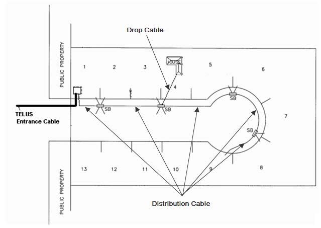
5.5 Strata Developments - Strata Bare Land
The following is an example of a Strata style development where the TELUS Entrance Cable is
terminated and protected in a structure near the entrance to the development.
The Distribution Cables and Drop Cables must meet all requirements for Outdoor Rated Cabling.
Notes:
1. A Transition Housing must be placed at each house for transitioning the outdoor rated drop
cable to the 4 pair CAT-5e inside wire from the TELUS Hub.
2. When individual 4 pair drops are placed to each housing unit, all 4 pairs of the drop and the 4
pair CAT-5e inside wire from the TELUS Hub must be terminated on an approved CAT-5e
connector. (i.e. a grease filled BIX strip complete with BIX Wire Retainer clips).
Page 19 of 22 2011-05-246. Testing MDU Installation, Cabling and Multimedia Outlets
6.1 Test Equipment Recommendation
Contractors will require effective test gear to validate and verify correct wiring of each Multimedia Outlet
and of each cable run back to the Distribution Device.
TELUS recommends devices that can perform the following tests:
1. incorrect terminations
2. opens; shorts
3. faults or breaks or damaged wires
4. distance or location to break
5. splits
6. crossed wires
7. reversed wires
8. cable length
9. grounds
6.2 Verification Tests – cable and multimedia outlets
Note: These verification tests for residential wiring do not include a test for the information carrying
capacity of the link. Home network links are shorter than those for commercial uses and so do not suffer
as much loss of capacity. Good capacity can be expected when guidelines for routing and installations
have been adhered to.
Here are the test/verification steps for CAT-5 cable (or better, 5e/6/6e) and terminations. Mark V on the
"Outlet/Drop".
No. Step Expected Result Pass/Fail
Plug test instrument into 8-Pin modular jack (often
1
referred to as RJ-45) of Multimedia Outlet
Run Wire map test to ensure correct cable/socket wiring. Correctly wired to
2
Wire map tests cover: shorts, miswires, crosses, etc Pass
3 Run Length test: Required less than 90m (295 ft) Less than 90m
Check for cable faults (indicated by distance Open or no faults or zero
4
Short is away from outlet under test) distance
5 Check far end connector is not faulty no faults
Page 20 of 22 2011-05-246.3 In-suite Network Certification - Test Verification Check Sheet
The Developer/Contractor is responsible for providing TELUS with connectivity
verification for each installed run.
Installation date: / / Crew: _________________
Service contact Ph.: (____) ______________________
Installation #: Installer Company Name:
MDU Dev Name: Address:
Address: City:
Lot/Block: Province: Postal Code:
City: Phone:
Province: Postal Code: Email:
SUITE NO:
Example is shown on first line with number of drops per cable type.
Note C3 = Category 3 C5= Category 5 C5e= Category 5e C6 = Category 6
Test – V = Verified for continuity, wiremap, and length, C = Certified to cabling performance specified per the ANSI/TIA/EIA-570-A or B Standard
Coax OTHER / NOTE
Outlet / Drop Voice Data Init.
/Other
RG-11
RG-6
Test
Test
Test
C5e
C5e
C3
C5
C6
C3
C5
C6
Location
Example: MBR01 1 V 1 C 2 V primary Multimedia Outlet
Page 21 of 22 2011-05-246.4 MDU 8-PIN Modular (RJ-45) Jack Terminating Instructions
The 8-PIN Modular Jacks are to be terminated according to TIA-568-A pin out assignments as below.
Standard 4-Pair Wiring Color Codes
Pair 1 T White/Blue
R Blue/White
Pair 2 T White/Orange
R Orange/White
Pair 3 T White/Green
R Green/White
Pair 4 T White/Brown
R Brown/White
Page 22 of 22 2011-05-24
Date Controlled Material
Use Current Version ONLY at Web Site:
telus.com/bics
©TELUS Privacy TELUSYou can also read