Simulation of slot and round synthetic jets in the context of boundary-layer separation control
←
→
Page content transcription
If your browser does not render page correctly, please read the page content below
Downloaded from http://rsta.royalsocietypublishing.org/ on September 26, 2015

                                                  Phil. Trans. R. Soc. A (2011) 369, 1495–1512
                                                                     doi:10.1098/rsta.2010.0363

                                             REVIEW

   Simulation of slot and round synthetic jets in
  the context of boundary-layer separation control
                 B Y M ICHAEL A. L ESCHZINER*           AND   S YLVAIN L ARDEAU
         Department of Aeronautics, Imperial College London, London, UK

Synthetic jets—also referred to as mass-less jets—offer the potential of effective,
on-demand, fluid-based control of separating boundary layers on highly loaded
aerodynamic surfaces, without the need for a mass source. However, the control authority
that may optimally be derived from such jets, and any generality of the underlying flow
physics are obscured by the wide range of geometric and flow parameters that contribute
to their performance characteristics. The present article reviews the state-of-the art in the
area of computational modelling and simulation of synthetic jets, with emphasis placed
on key fluid-mechanics phenomena. The review is divided into two principal parts, one
focusing on slot jets and the other on round jets. Within the latter part, ongoing research
by the authors on the simulation of synthetic jets discharged into a separated boundary
layer is highlighted as an example of the current status in this area.
             Keywords: synthetic jets; computational prediction; large-eddy simulation;
                                     boundary-layer separation

                   1. Basic features and relevance of synthetic jets

A synthetic jet—strictly a pair—is formed as a consequence of a fluid being
pushed and pulled periodically through an orifice. In highly simplified terms, this
actuation causes two trains of vortices to be formed, each set merging, in a time-
averaged sense, into jet-like entities. In what follows, the term injection should
thus be understood as the outcome of the time-dependent actuation that involves
consecutive expulsion and suction phases within an actuation period.
   The earliest technological realization and exploitation of a synthetic jet appears
to be that reported by Ingard [1], in the context of the design of acoustic
resonators. A brief discussion by Saffman [2], under the heading dynamics
of vorticity, of a periodically ejected train of interacting vortices, visualized
experimentally by Glezer [3], is perhaps the earliest account pertinent to the
fluid mechanics of a synthetic jet discharged into stagnant surroundings.

*Author for correspondence (mike.leschziner@ic.ac.uk).

One contribution of 15 to a Theme Issue ‘Flow-control approaches to drag reduction in
aerodynamics: progress and prospects’.

                                                1495           This journal is © 2011 The Royal Society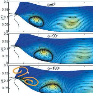
Downloaded from http://rsta.royalsocietypublishing.org/ on September 26, 2015
1496 M. A. Leschziner and S. Lardeau
(a) (b)
(c) (d)
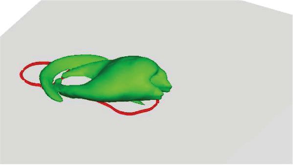
Figure 1. Phase-averaged images of a round synthetic jet actuated upstream of turbulent separation
(§4) covering a single cycle; the images show contours of the pressure Laplacian at four different
phases during the cycle (red lines indicate local reverse flow): (a) 3p/8, (b) 5p/8, (c) 7p/8 and
(d) 9p/8.
In a practical setting, a synthetic jet is most frequently realized by oscillating
the wall of a cavity on one side of the orifice, while on the other side, the vortical
structures leaving the aperture interact with a boundary layer, as illustrated in
figure 1 with reference to two cases, which differs by the geometry of the aperture
(slot or round jet). These cases are presented in more details in §§3 and 4.
The mass-flow rate through the aperture typically (but not necessarily) follows
a near-sinusoidal pattern, so that the net mass-flow rate through the orifice is zero.
However, because of the irreversibility of the motion, associated with viscosity
and separation from the orifice edge, there is a net expulsion of vorticity from
the aperture (figure 1). During the expulsion stage, vorticity flux and associated
circulation (the time integral of the former) are ejected into the outer flow
and propagate away from the orifice. In the following suction stroke, the fluid
ingested originates predominantly from the area close to the wall surrounding
the orifice. Hence, this suction does not reingest the circulation ejected, and the
result is a net unsteady ejection of vorticity that, if time averaged, gives rise to a
jet with broadly similar (far-field) characteristics to those of a continuous jet—
albeit weaker in intensity [4]. This process, appropriately configured, allows the
character of the cross flow to be influenced—or controlled—without the need for
a mass source. A more detailed discussion of the fluid mechanics associated with
the images in figure 1 will be given in §§3 and 4.
Practical interest in synthetic jets, in the context of flow control, is rooted in
their potential for effecting on-demand attenuation or prevention of separation
of boundary layers subjected to adverse pressure gradient. In simple terms, a
synthetic jet causes additional mixing by streamwise vorticity and turbulence,
without the introduction of solid, fixed, vortex generators. This is particularly
attractive in air transportation where specific boundary-layer control may be
needed in high-lift operation during landing or in low-momentum junction
regions, whereas such control may be disadvantageous in cruise conditions.
Phil. Trans. R. Soc. A (2011)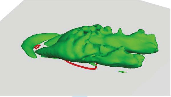
Downloaded from http://rsta.royalsocietypublishing.org/ on September 26, 2015

                                Review. Simulation of synthetic jets                        1497

   While the flow-control potential of synthetic jets should be evident from the
above comments, in general terms, the details of this control depend greatly
on many parameters, with each set giving rise to different associated fluid-
mechanics scenarios. The most important variable is the geometry of the orifice.
The behaviour of the ejected vortices and the manner in which they interact with
the cross flow are much more complicated in the case of circular jets than slot
jets. The interaction is also weaker and more subtle. Other important variables
include the angle of injection, the position of the orifice relative to the nominal
separation location in the uncontrolled flow, the cavity and orifice-duct shape,
the jet-to-outer-flow momentum ratio, the frequency of the injection, the duty
cycle, the mean and turbulence properties of the boundary layer in the cross
flow, the Reynolds number of the jet and the boundary layer, and the details of
the separated flow to be controlled. This complex multi-dimensional parameter
space makes it extremely difficult to derive general conclusions and guidelines on
the control effectiveness of synthetic jets, as a single category, and the associated
fluid mechanics. Hence, past studies provide no more than a (sparse) knowledge
base that yields general pointers, rather than quantitative data. In the following
review, we focus on some common elements, derived from computational studies
only. Attention is restricted to the control of separation on semi-infinite surfaces,
while the subject of the interaction of separation with circulation over closed
bodies is excluded. Elements of experimental research are reviewed by Glezer [5]
in the present issue.

                                  2. Computational challenges

Prior to a discussion of specific studies, grouped under slot jets and circular jets,
it is appropriate to highlight some common challenges that arise in efforts to
compute the flows in question.
   Synthetic-jet scenarios have been computed with both statistical (Reynolds-
averaged Navier–Stokes; RANS) models and with scale-resolving approaches
(large-eddy simulation (LES) and direct numerical simulation (DNS)). The
obvious attraction of RANS lies in its economy: it gives (nominally) a phase-
averaged representation of the flow, and thus allows far larger time steps
to be used in the computational solution, this time step being scaled with
the injection period, rather than with the turbulent motions; it allows (again
nominally) statistically spanwise-homogeneous geometries to be computed in a
two-dimensional fashion; and it permits a coarser mesh to be used, as the phase-
averaged fields of statistical quantities vary much more smoothly than the field of
instantaneous turbulent motions. However, there are potentially serious penalties
to pay for this economy: RANS models are ill-suited to time-varying flows,
especially if the frequency of this variation is of the same order of magnitude
as that of the turbulent motion, as is the case in many applications; RANS
models are known to often give a poor representation of separated flows, even if
statistically steady, owing to insufficient level of turbulence activity predicted in
the separated shear layers; and RANS models cannot properly represent spectral
resonance between the actuation and natural instability modes in the upstream
boundary layer and the separated flow. While there are examples of the RANS
method giving reasonable first-order representations of the primary effects of

Phil. Trans. R. Soc. A (2011)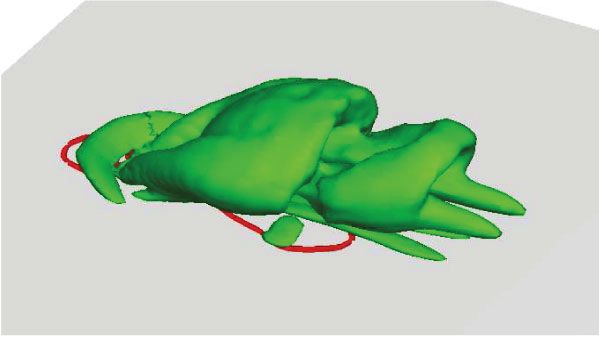
Downloaded from http://rsta.royalsocietypublishing.org/ on September 26, 2015

1498                            M. A. Leschziner and S. Lardeau

synthetic jets (e.g. [6,7]), the details of the representation are model dependent.
Also, as demonstrated by Dandois et al. [6], for the case of circular-jet injection
into an attached boundary layer, the jet structure returned by RANS modelling
is very far from that returned by the corresponding high-quality scale-resolving
simulation.
   On the other hand, scale-resolving simulations pose a number of major
challenges, some not encountered in most other flows. Perhaps, the most serious
one is the scale disparity between the very small jet orifice and the large body
of fluid being controlled by the jet, the linear ratio of dimensions being of the
order of 0.01 or less. This is especially so in the case of circular jets, and gives
rise, on its own, to a serious grid-resolution problem. Although the orifice need
not be very small, in principle, its size is constrained, in practice, by the need
for high expulsion velocity, low cavity volume and surface integrity. The need
to resolve the viscosity-affected near-wall region of the boundary layer, which is
usually extensive in size and at high Reynolds number, substantially aggravates
the resource problem. Next, the nature of the expulsion and suction phases,
constituting the complete injection cycle, necessitates, in principle, the resolution
of the cavity and duct from which the jet issues and into which fluid is being
drawn from the boundary layer during the ingestion part of the cycle. This is,
again, especially important in circular-jet injection because the jet properties at
the orifice, and thus its evolution in the boundary layer, are strongly affected—
more so than in slot jets—by the boundary layer and by the state of the flow
inside the cavity. In addition, when the working medium is air or another gas,
the acoustic characteristics of the cavity are important, and Helmholtz resonance
effects may be influential. However, this introduces a time scale that is very much
smaller than the injection period and also of the influential turbulent motion in
the boundary layer. Yet, a further problem posed by the unsteadiness is that
statistically converged time-averaged and, even more so, phase-averaged and
stochastic turbulence data are extremely difficult to obtain because this requires
many injection cycles to be included in the simulation, and also because there are
no homogeneous directions in circular-jet actuation (unlike in slot-jet injection)
over which integration can be performed. Finally, the boundary layer approaching
the jet cannot be computed from its inception, far upstream, and this necessitates
the prescription of turbulent (unsteady) conditions across an inflow plane fairly
close to the jet. The last item is, strictly, pertinent only to high-fidelity DNS
and LES computations. In contrast, in detached-eddy simulation, the attached
flow upstream of injection or separation is computed with a RANS method, and
the LES component is activated upon separation being encountered. Examples
are the studies of Qin & Xia [8] and Lopez & Moser [9]. Self-evidently, the
advantage of this hybrid approach is economy, but the disadvantage is loss of
fidelity because the spectral nature of the upstream flow is influential on the
jet/boundary-layer interaction.

                                            3. Slot jets

There is a marked predominance in the literature of studies that focus on
geometrically two-dimensional (or nearly two-dimensional) slot-jet configurations
Phil. Trans. R. Soc. A (2011)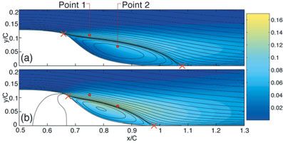
Downloaded from http://rsta.royalsocietypublishing.org/ on September 26, 2015

                                Review. Simulation of synthetic jets                        1499

relative to circular jets. There are several reasons for this, some fairly obvious,
others less so.

    — The control authority that can be exercised with a slot jet, or with several
      high-aspect-ratio rectangular orifices forming a slot, is substantially greater
      than that with a circular jet having a diameter equivalent to the slot
      width—unless a dense array of closely spaced circular jets is used. This is
      mainly owing to the far greater momentum and vorticity flux ejected across
      the entire spanwise extent of the flow. Hence, the observed sensitivity of
      the separation to the actuation is substantial.
    — A slot jet offers greater potential for achieving an advantageous spectral
      resonance with two-dimensional instability modes in the separated
      shear layer.
    — The statistical properties of slot jets can be adequately characterized
      by the conditions across a single spanwise plane. This is advantageous,
      in terms of data volume and costs, in both experimental campaigns
      and computational studies, especially if the latter are undertaken within
      the RANS framework, in which case, highly economical two-dimensional
      computations are possible. In the case of scale-resolving simulations (DNS
      and LES), an advantage arising from the two-dimensionality of slot jets
      is that their meshing (especially with structured grids) is much easier and
      that the spanwise mesh density can be kept uniform.
    — Because of the strength of the control derived from slot jets, the fidelity
      of the solution relies less on the inclusion of the discharge duct and the
      full cavity. Indeed, both are often ignored, with the discharge conditions
      prescribed explicitly at the jet orifice or slightly into the discharge duct.
      Moreover, the detailed resolution of the near field around the jet orifice is
      less important than for a circular jet, and this permits a lower grid density
      around the slot.
    — In basic computational studies in external aerodynamics, attention often
      focuses on two-dimensional aerofoil sections, rather than on realistic three-
      dimensional swept wings, principally because of the economy offered
      by two-dimensional RANS methods in spanwise-homogeneous conditions.
      This has also motivated related two-dimensional studies of synthetic-jet
      control with slot jets on aerofoils, within which a range of parametric
      variations could be explored economically (e.g. [10,11]). Clearly, however,
      this approach represents a major simplification of reality, with attendant
      penalties to physical fidelity.

   The generic fluid-mechanic processes by which synthetic slot jets effect
separation control may be explained with reference to the configuration shown
in figure 2, together with the instantaneous flow visualization of figure 1a. This
particular flow is, without doubt, the most popular computational test case in
its category, because of the availability of extensive experimental data obtained
at the National Aeronautics and Space Administration (NASA) by Greenblatt
et al. [13,14] for a range of injection and suction conditions, among them
synthetic-jet injection. These data formed the basis of two major workshops: one
organized by NASA [15] attracting more than 50 computational contributions by
13 participants; and the other, more modest, organized by the European Research
Community in Flow, Turbulence and Combustion [16].
Phil. Trans. R. Soc. A (2011)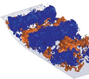
Downloaded from http://rsta.royalsocietypublishing.org/ on September 26, 2015

1500                            M. A. Leschziner and S. Lardeau

     (a)                                      (c)

     (b)

Figure 2. Control of separation behind a dune-shaped hump with a synthetic slot jet: results
from an LES study by Avdis et al. [12], corresponding to experiments by Greenblatt et al. [14].
(a) Instantaneous realization, (b) time-averaged recirculation with and without actuation and
(c) phase-averaged stream traces relative to experimental data.

   A boundary layer having a momentum-thickness Reynolds number of about
6000 is made to flow over a dune-shaped hump, separating slightly downstream
of its crest and forming a recirculation zone of a length of approximately 0.4 of
the bump chord. Stochastic turbulence apart, this zone is essentially steady in
so far as it does not display coherent time-dependent motions. The synthetic jet
with a close to sinusoidal mass-flux variation is discharged almost horizontally
and slightly upstream of the nominal separation line at a maximum velocity of
0.77 times the free-stream velocity U∞ at a frequency of 138 Hz, corresponding
to a Strouhal number StL = fL/U∞ = 0.77, where L is the length of the separated
shear layer in the uncontrolled flow. The significance of this frequency will be
discussed later, but it is noted here that values in the range of 0.5–1.5 are
often observed to yield maximum reduction in separation, given fixed conditions
otherwise. It is also noted here that effective separation control relies on rather
high jet-velocity values, with maximum values typically in the range of 0.5–2
times the maximum velocity in the separated shear layer.
   Among the many solutions contributed by Rumsey et al. [15], those obtained
with RANS yielded recirculation-zone lengths, even for the baseline case, well
in excess of that observed experimentally, reflecting a serious underestimation
of the turbulence activity within the separated shear layer, especially with more
advanced anisotropy-resolving turbulence closures; this is an ubiquitous defect
observed in a variety of separated flows, especially when separation occurs on a
gently curved surface. In addition, RANS solutions cannot account properly for
any spectral resonance between the injection and natural instability modes in the
separated shear layer. Scale-resolving solutions for the synthetic-jet conditions
were contributed by You et al. [17], Saric et al. [18], Morgan et al. [19] and
Avdis et al. [12]. The results in figure 2 are taken from a study by Avdis
et al. [12], one that has been found to give particularly close agreement with
the experimental data.

Phil. Trans. R. Soc. A (2011)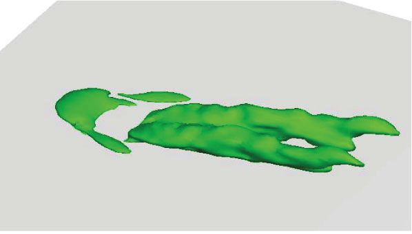
Downloaded from http://rsta.royalsocietypublishing.org/ on September 26, 2015

                                Review. Simulation of synthetic jets                        1501

   Figure 2a shows an instantaneous realization, visualized by iso-surfaces of
V = ±0.25U∞ . Although the flow is evidently highly three-dimensional, the
spanwise rollers associated with the injection are clearly recognized. Figure 2b
shows the injection to result in a substantial reduction in the time-averaged size
of the recirculation zone, by a process that will be discussed below. The predicted
reduction in length, 30 per cent, is close to that recorded experimentally, at
28 per cent. The most informative view is derived from phase-averaged fields,
such as those given in figure 2c, which compares computational with experimental
stream traces at four phases. The injection is seen to cause the recirculation
zone of the baseline flow (lower plot of figure 2b) to break up into a train of
smaller recirculation zones, with stretches of attached flow separating them. On
average, there are around 1.5–2 such regions present within the length of the
baseline recirculation zone. This can be understood upon noting that StL = 0.77,
in combination with a convection velocity of disturbances in the separated shear
layer of around 0.5U∞ , suggesting that a distance of about 0.65L separates
sequential jet-actuated pulses.
   Within a phase-averaged framework, the expulsion phase may be thought of
as the periodic injection of two vortex sheets, one on the underside and the other
on the upper side of the synthetic jet, which roll up into the vortices sketched in
figure 2c. The upper anti-clockwise vortex is carried upward and forward by the
combined action of the Magnus force [20] and forward/upward-directed advective
motion from the separating shear layer. The lower vortex is trapped in the near-
wall layer and enhances the clockwise vorticity in the recirculation zone. The
upper train of vortices is to oppose the vorticity in the separated shear layer,
accelerate this layer and induces a Coanda-like streaming effect that favours
attachment. The intermittent reattachment that results from the injected vortices
translates into a substantial increase in time-averaged turbulent shear stress in
the separated shear layer and hence early reattachment. The details of the process
are likely to be considerably more complicated. In particular, the periodic extra
straining can be expected to cause extra production of stochastic turbulence
energy and stresses, i.e. components that are entirely different from the periodic
(phase-averaged) contributions. This distinction will be pursued in §4, in relation
to round jets.
   Computational studies that offer reinforcement of some of the arguments given
above, as well as providing much additional insight into pertinent fluid-mechanic
interactions, are those of Dandois et al. [21], Neumann & Wengle [22] and Dejoan
& Leschziner [7]. The third study, in particular, reports LES-derived predictions
of a synthetic slot jet injected at 45◦ into a channel flow that separates from a
backward-facing step at a step-height Strouhal number, StH = 0.2, corresponding
to StL = 1, where L ≈ 5H is the baseline recirculation length. Experimental studies
for the same flow by Yoshioka et al. [23] demonstrate a maximum reduction in
the baseline separation length of around 30 per cent, well reproduced by the
simulation. Phase-averaged vortical patterns reported by Dejoan & Leschziner [7]
are remarkably similar to those in figure 2, despite the very different geometry,
large differences in flow conditions, especially in the ratio of pre-separation
boundary-layer momentum thickness to the length of the separated shear layer,
and a factor 30 difference in the respective Reynolds numbers. The LES study
reveals, among a number of interactions, that the increase in the time-averaged
shear stress, primarily responsible for reducing the separated region, results not

Phil. Trans. R. Soc. A (2011)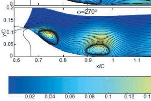
Downloaded from http://rsta.royalsocietypublishing.org/ on September 26, 2015

1502                            M. A. Leschziner and S. Lardeau

only from the coherent vortical motions induced by the actuation, but also from
an enhancement in mixing provoked by extra generation of stochastic turbulence,
owing to unsteady straining in areas lying roughly midway between consecutive
vortical structures.
   A topic that has been the subject of much debate is the role of resonance
between the frequency of the actuation and natural instability modes in the
baseline flow. Discussions around this subject pertain virtually exclusively to
slot jets, as opposed to round jets, because resonance relies on the actuated
disturbances being able to interact with two-dimensional instability modes.
There are at least three instability modes that are assumed to be influential in
reattaching shear layers: the shear-layer, the shedding (or step) and the flapping
modes. A fourth that has been mentioned, albeit rarely, is the bursting frequency
of hairpin vortices in the boundary layer approaching separation, but there is
virtually no evidence that this mode is pertinent. The shear-layer mode is linked
to Kelvin–Helmholtz instabilities in the separated shear layer. Hasan & Khan [24]
show that this is characterized by Stq = 0.011, where q is the momentum thickness
at the location of separation. For turbulent separation from a backward-facing
step, Hasan & Khan [24] also observe, based on controlled-excitation experiments,
that the shedding mode is characterized by StH = 0.185, independent from the
state of the separated shear layer. An argument advanced by Hasan & Khan [24],
also stated in Dandois et al. [21], is that the shedding mode is linked to the
shear-layer mode by a sequence of vortex pairing, with the former becoming the
dominant mode as the shear layer evolves. This is the reason why the actuation
frequency for separation control is generally chosen to be around StH = 0.2,
regardless of the upstream boundary-layer characteristics. If the length of the
separated shear layer is taken to define the Strouhal number, the above value for
StH translates to StL in the range of 0.5–1, depending on the flow. Indeed, Dandois
et al. [21] provide a table of around 20 flows for which they list the shedding-mode
Strouhal number (based on separation length) to be mostly in the range of 0.5–0.8.
As the convection velocity in the shear layer is around 0.4 times the free-stream
velocity, the above range suggests the presence of around 1.5 actuation-induced
vortical structures along the separated shear layer, as is seen in figure 2.
   It is interesting to observe that the actuation frequency in the case of
figure 2, StH = 0.2, translates to Stq = 0.01, while the corresponding value in the
case examined by Dejoan & Leschziner [7] is Stq = 0.03, quite different from
the shear-layer mode given by Hasan & Khan [24]. Yet, Yoshioka et al. [23]
show this actuation frequency to give the maximum reduction in recirculation
length, supporting the supposition that the shear-layer mode is of subordinate
importance to the optimum actuation frequency. Consistently, Neumann &
Wengle [22] also report, based on a range of LES computations for a flow
separating from a curved step, an optimal actuation frequency at StH = 0.2, which
corresponds to StL = 0.8. In contrast, Dandois et al. [21] argue, for the case of
the curved backward-facing step, that their choice of actuation at StH = 0.14,
corresponding to StL = 0.5, is the most appropriate, as it is consistent with
the frequency of the first sub-harmonic of the Kelvin–Helmholtz mode in the
separated shear layer, associated with pairing. This frequency suggests that
the optimum actuation is characterized by the presence of a single vortical
perturbation within the separated shear layer at any one time. It is evident,
therefore, that there is some uncertainty and inconsistency in the interpretation

Phil. Trans. R. Soc. A (2011)
Downloaded from http://rsta.royalsocietypublishing.org/ on September 26, 2015

                                Review. Simulation of synthetic jets                        1503

of the links among the shear-layer mode, the shedding mode and the actuation
frequency. On the whole, however, the level of disagreement with respect to the
choice of actuation frequency is relatively modest, with most studies suggesting
that the maximum reduction in recirculation is achieved with actuation in the
range of StL = 0.5–1. Finally, the third instability mode, the flapping mode,
is associated with a temporally varying imbalance between the entrainment
rate into the lower part of the separated shear layer and the amount of fluid
returned to the recirculation bubble in the reattachment zone [25]. This mode
is characterized by frequencies substantially lower than that of the shedding
mode, and is generally regarded as irrelevant to any issues of resonance with
the actuation.
   A major question mark against the generality of the above observations appears
to arise from experimental observations by Amitay et al. [26] and Glezer &
Amitay [27], among others, that actuation frequencies are an order of magnitude
higher than those considered earlier, i.e. StL = 10 can be highly effective in
controlling separation from cylinders and aerofoils. Woo & Glezer [28] also show,
by reference to a range of experiments on an aerofoil configuration, that an
asymmetric duty cycle—a very short ejection stroke, followed by a relatively
long ingestion stroke—is also highly conducive to separation control. Both
observations are intriguing. At this high frequency, the actuation is spectrally
decoupled from any macro scales of the controlled flow. In fact, this frequency
is observed to be within the inertial sub-range of the turbulence spectrum at
relatively low Reynolds numbers, and thus cannot be the source of interactions
with large energetic scales. The process by which control is effected is then akin
to that of a continuous jet that reduces, by streaming, the difference between
the actual solid body and the virtual body that is created by displacement
and separation. In effect, the synthetic jet increases the Coanda mechanism by
accelerating the flow at the edge of the separation region. As to the temporal
details of the injection cycle, a short explosive ejection is thought to avoid the
formation of trailing vortices, or a trailing vortex sheet, behind a head vortex,
due to vorticity saturation in the vortex [29]. Moreover, the weak and prolonged
suction stroke avoids a reingestion of ejected vorticity, so that all this vorticity is
used in the control process.

                                           4. Round jets

As noted earlier, round synthetic jets pose considerably greater computational
challenges than slot jets. Among the most important are those that arise from
(i) the need for a much higher local resolution around the jet orifice, (ii) the
importance of accounting for the flow in the cavity and jet duct, (iii) associated
with (ii), the higher complexity of the geometry, requiring meshes of different
topologies to be interfaced (unless the mesh is unstructured), and (iv) the absence
of statistically homogeneous directions that aid the derivation of converged
statistical information by spanwise averaging. The main argument for including
the cavity (or cavities) in the simulation arises from the observation—for example,
by Leschziner et al. [30] and Dandois et al. [6]—that the phase-averaged velocity
profiles across the orifice are highly asymmetric in space and irregular in time,
suggesting a strong interaction between the conditions at the jet exit and the

Phil. Trans. R. Soc. A (2011)
Downloaded from http://rsta.royalsocietypublishing.org/ on September 26, 2015
1504 M. A. Leschziner and S. Lardeau
cavity. An additional, potentially influential, process is the transport of cavity
turbulence into the cross flow during the expulsion phase, especially pronounced
when the orifice duct is short.
In view of the above comments, it is not surprising that relatively few
computational studies have been published on round jets. Of these, most relate
either to laminar conditions [31] or to injection into the attached turbulent
boundary layers [6,32]. A very recent study of laminar round-jet injection
into a separating laminar boundary layer undergoing transition is that of
Ozawa et al. [33]. One additional fact that has militated against the emergence of
a richer literature on round jets is that a practically effective exploitation of round
jets is likely to require several streamwise rows of jets, each consisting of many
jets that are separated, typically, by five orifice diameters or less. The simulation
of this scenario is clearly a monumental task, and this has encouraged a focus on
single or twin jets, the latter assumed to represent a spanwise periodic row.
Some of the basic fluid-mechanic interactions between a round jet and a
boundary layer may be discussed with reference to the particular configuration
shown in figure 1, which provides images of the phase-averaged structures
evolving during the actuation cycle of a turbulent jet injected into a turbulent
boundary layer upstream of separation (see §5 for details). However, there
is a material dependence of the details of the interaction on the frequency
and intensity of the actuation (e.g. jet/boundary-layer velocity ratio), and the
generality of the discussion is thus necessarily limited. This is illustrated, for
example, by computations of Zhou & Zhong [31], supported by experiments
of Jabbal & Zhong [34] for various laminar-flow conditions. A relatively low
actuation frequency is observed to give rise to hairpin structures with trailing
vortex legs (or tails), while high frequency results in the ejection of essentially
isolated, tilted and streamwise-stretched vortex rings, with their head lifted by
the Magnus force [20]. Low-frequency injection is associated with large stroke
T
length, L∗ = L/D = (1/D) 0 0 Vjet dt, where T0 is the expulsion portion of the
injection cycle, while high-frequency injection gives rise to short stroke length.
The heads of the ejected vortices provoke large periodic disturbances in the outer
layer into which they penetrate and in which they propagate, by virtue of the
rotational motions they induce, which cause outer boundary-layer fluid to be
drawn towards the wall and inner fluid to be pulled upwards. The streamwise
vorticity associated with the streamwise-stretched portions of the vortex rings,
or the legs of the hairpin vortices, likewise give rise to a convective exchange of
near-wall and outer fluid. The motion on the lower side of the vortices, towards
the jet centre plane, then induces secondary vortices closer to the wall by a
streamwise realignment of initially spanwise vorticity in the boundary layer,
combined with the vorticity ejected with the jet from the downstream portion
of the orifice edge, which is trapped within the slow near-wall layer. In simplified
terms, the transverse field is characterized by a periodic formation of two pairs
of counter-rotating vortices, one strong outer pair and a weaker inner pair.
Both contribute, although unequally, to the process of separation control, by
wall-normal momentum mixing, the contribution of coherent motions to the time-
mean stresses and the extra generation of stochastic turbulence by the unsteady
straining associated with the periodic actuation. Both Leschziner et al. [30] and
Dandois et al. [6] show that, as the Reynolds number increases, the impingement
of the boundary layer onto the exiting jet plug results in a multiplicity of vortex
Phil. Trans. R. Soc. A (2011)Downloaded from http://rsta.royalsocietypublishing.org/ on September 26, 2015
Review. Simulation of synthetic jets 1505
10
8
6
4
y/H
2
0
y
–5 –2
x 0
z 5 0 H
x/H 10 2
15 z/
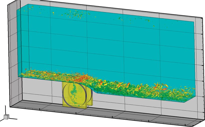
Figure 3. Global view of flow configuration investigated in §5: turbulent boundary layer separating
from a rounded step in a duct, with two synthetic jets actuated from two cylindrical cavities.
rings wrapped around the ejected jet fluid. The resolution of these features is
poor (or non-existent) when the numerical-grid density is coarse and/or a RANS
method is used.
Two major studies have been published on the interaction between round
jets and the attached turbulent boundary layer. One, already mentioned, is by
Dandois et al. [6], while the other is by Wu & Leschziner [32]. These studies
are pertinent to the present account in so far as they quantify the effect of the
actuation on the boundary layer downstream of the orifice, but within a region
that lies upstream of the separation line, as is the case in the flow discussed in
the next section.
The two studies target different configurations, corresponding to two related
sets of experimental data, but the principal flow conditions are not dramatically
dissimilar: Req = 2380 and StD = 0.069, where D is the jet diameter, and a ratio
of maximum jet velocity to free-stream velocity of 2.0, in the case of Wu &
Leschziner’s study, and Req = 4275, StD = 0.019 and a velocity ratio of 1.45, in
the study of Dandois et al. The global mesh size was also similar in both cases
(about 9 × 10⁶ nodes), but the more flexible H–O grid topology in the latter study,
relative to a pure H-topology coupled with the immersed boundary method in the
former study, allowed a much finer resolution than in the former around the jet
orifice—albeit at the penalty of significant local mesh distortions. In both cases,
the cavity below the jet was included in the simulations, and the computational
inflow conditions included (at least in some simulations) a full representation of
the unsteady turbulent state of the boundary layer.
While the studies reveal a wide range of interesting features, the most
important common observations may be summarized as follows:
— the lateral domain within which the jet modifies the base flow is
narrow, extending to only around one dimension on either side of the jet
centre plane,
Phil. Trans. R. Soc. A (2011)Downloaded from http://rsta.royalsocietypublishing.org/ on September 26, 2015
1506 M. A. Leschziner and S. Lardeau
— two major time-averaged vortex pairs are formed, one in the outer portion
of the boundary layer, reflecting the trajectory of the jet, and another
counter-rotating close to the wall,
— a modest acceleration of the streamwise flow near the wall occurs, owing
to streamwise momentum being transported towards the centre plane by
the near-wall vortex pairs,
— substantial distortions are caused in the phase-averaged velocity profiles
in the near-orifice field, associated with near-wall flow acceleration and the
presence of a distinct velocity maximum in the region in which the head
of the ejected vortex induced flow acceleration,
— the control effect of the actuation decays rapidly beyond around x/D = 5,
following a modest increase of about 30 per cent in the boundary-layer
displacement and momentum thicknesses, and
— strong distortions arise in the velocity field across the orifice, as already
noted, suggesting that it is imperative to resolve the flow below the
orifice.
The most important lesson to carry forward from the above observations
is that the control authority exercised by an isolated round jet is modest,
despite its high momentum. This is simply a consequence of the large-scale
disparity between the jet and the flow being controlled. As already noted, this
implies the need for large arrays of circular jets if strong control authority is to
be exercised.
5. Separation control with round jets
Some of the general arguments presented in the previous section are illustrated
and amplified in the present section with reference to ongoing studies pursued by
the authors. Specifically, results arising from a particular study are introduced
and discussed to convey an impression of the current state of the art and the
potential offered by scale-resolving simulations in gaining insight into physical
phenomena.
The configuration examined is shown in figure 3: a pair of jets, 10 orifice
diameters D apart, injected normally into an attached boundary layer
that separates around 8D, further downstream from a rounded step. The
computational geometry and flow conditions adhere closely to those of an
experimental study by Zhang & Zhong [35].
The step itself is an extension of one investigated by Song & Eaton [36], without
any connection to flow control. The jets are actuated by shaking pistons on the
sides of the circular cavities shown in figure 3. The upstream-shifted location of
the jets is constrained by the need to accommodate the cavities and the shaking
mechanism below the curved wall. The Reynolds number of the boundary layer,
based on the free-stream duct velocity, Uin , and step height, H , is 13 700, the
boundary-layer momentum thickness Reynolds number is 1150, the normalized
peak injection velocity, Vr /Uin , is 1, the jet Reynolds number, based on D and Vr
is 2750, and the injection-cycle frequencies investigated are f = 40 and 200 Hz. The
former value corresponds to a Strouhal number, St = fUin /H of 0.19, equivalent to
Str = fUin /Lr of approximately 0.7, where Lr is the length of the recirculation zone
Phil. Trans. R. Soc. A (2011)Downloaded from http://rsta.royalsocietypublishing.org/ on September 26, 2015
Review. Simulation of synthetic jets 1507
in the unactuated flow. As discussed earlier, values in the range of 0.5–1.0 have
been observed in various studies of slot jets to yield a close-to-maximum response
to the actuation, and this is related to shedding-mode instability in the separated
shear layer forming the outer region of the recirculation zone. It must be pointed
out, however, that the instability mode in question is largely two dimensional in
character, so that the strongly three-dimensional and local perturbation effected
by the circular jets is not expected to have the same significance and impact, in
terms of the actuation frequency, as in the case of slot jets.
The solution domain is treated as spanwise-periodic, includes two jets and
extends from the lower wall to the upper duct wall of the experimental wind
tunnel. The boundary layer on the lower wall is resolved with high fidelity on a
fine grid, while the much less important upper-wall boundary layer is resolved on
a coarser grid with the aid of a log-law-based wall function. The inlet conditions
of both boundary layers are specified by means of a database of 5000 fields
extracted from a precursor boundary-layer simulation. The grid used to cover
the domain in figure 3 is a multi-block finite-volume ensemble, comprising some
12.8 × 10⁶ cells in total. The cavity and orifice are accommodated with the
aid of an immersed boundary treatment. The LES formulation advances the
velocity field in time by means of a fractional-step method incorporating second-
order approximations for the fluxes and a new third-order Gear-like scheme
documented by Fishpool & Leschziner [37]. Zero divergence is secured by solving
the pressure Poisson equation, which combines the application of an implicit
successive over-relaxation (LSOR) method with a multi-grid scheme. Any odd–
even oscillations are counteracted by a dynamic total-variation-diminishing-like
wiggle-suppression scheme, which introduces a minimal amount of second-order
upwind-weighted differencing. Subgrid-scale turbulence is accounted for by way
of the Germano–Lilly dynamic model or by a local mixed model (involving no
averaging), both giving very close results.
A global view of the effectiveness of the actuation is conveyed in figure 4.
This compares, in figure 4a, the separation and reattachment behaviour as
derived from the conditions closest to the wall (y + O(1)); in figure 4b, velocity
profiles; and, in figure 4c,d, streamwise turbulence-intensity profiles in both the
baseline and actuated flows. The most important observation arising from the
comparisons is that the influence of the actuation on the separation is modest,
with computation and experiment showing a very similar response. Thus, the
recirculation bubble is shortened, but only by 17 per cent. The velocity profiles
clearly indicate that injection leads to the elevation of the velocity in the near-wall
region, thus delaying separation. Moreover, it is clear that another consequence
of the injection is a major perturbation of the velocity in the outer region of
the boundary layer, owing to the strong penetration of the head of injected
jet across the boundary layer (cf. figure 1). This latter effect is arguably not
beneficial in so far as it reflects an input of energy into a region that plays
a subordinate role in controlling the structure of the near-wall region. Hence,
the implication is that a wall-normal injection at high velocity is not optimal
and that other arrangements need to be pursued, for example shallow injection
against the boundary layer, an arrangement currently being examined by the
authors. Profiles of the streamwise turbulent stress show a pleasing agreement
with experiments, and it is especially noteworthy that the near-field behaviour
of the jet has been well captured. Interestingly, a close examination shows the
Phil. Trans. R. Soc. A (2011)Downloaded from http://rsta.royalsocietypublishing.org/ on September 26, 2015
1508 M. A. Leschziner and S. Lardeau
(a) 3.5 (b)
1.2
3.0 Lsep /H 1.0 x/H = 0.32
xsep /H, Lsep /H
2.5 0.8
x/H = 1.27
jet width
0.6
U/Uin
2.0
0.4
1.5 0.2
1.0 xsep /H 0
–0.2
–0.8 –0.6 –0.4 –0.2 0 0.2 0.4 0.6 0.8 0.01 0.10 1.00
z/H yw /H
(c) 0.018 (d) 0.045
0.016 0.040
0.014 0.035
0.012 0.030
uu/Uin2
uu/Uin2
0.010 0.025
0.008 0.020
0.006 0.015 x/H = 1.27
0.004 0.010
0.002 0.005
x/H = 0.32
0 0
0.01 0.10 1.00 0.01 0.10 1.00
yw /H yw /H
Figure 4. Flow configuration shown in figure 3: (a) separation and reattachment location as a
function of the spanwise direction, (b) velocity profiles for different streamwise locations and
(c,d) mean streamwise-stress profiles uu/Uin 2 . Experimental results are shown with symbols and
simulations with lines. Open circles and solid lines, baseline case; filled circles and dashed lines,
with synthetic jets at StH = 0.2.
level of streamwise stress (and also shear stress) in the separated region of the
actuated case to be somewhat lower than in the baseline flow. This reflects
the weaker recirculation, the weak contribution of the periodic component to
the uv correlation beyond x/H = 2 (see below) and the delayed separation caused
by the actuation.
One especially interesting aspect of a periodic jet injection is the relative
contribution of the periodic and stochastic turbulence component to the total
turbulence quantities. The effect of actuation itself can be separated from the
background stochastic motion by performing a triple decomposition of the flow
field based on the period of actuation T , i.e. any quantity f (x, t), can be written
as f (x, t) = f¯(x) + f˜(x, t/T ) + f (x, t), where f¯, f˜ and f are the mean, periodic
and stochastic components of f .
Profiles of the periodic, stochastic and total streamwise normal stress at
two streamwise locations are shown in figure 5. Close to the injection location
(x/H = 0 corresponds to 7D downstream of the injection), the periodic component
Phil. Trans. R. Soc. A (2011)Downloaded from http://rsta.royalsocietypublishing.org/ on September 26, 2015
Review. Simulation of synthetic jets 1509
(a) (b)
streamwise stresses
0.03
0.02 0.01
0.01
0 0
(c) (d)
0.03 0.03
streamwise stresses
0.02 0.02
0.01 0.01
0 0
0.001 0.01 0.10 1.00 0.001 0.01 0.10 1.00
(y – ywall)/H (y – ywall)/H
Figure 5. Flow configuration shown in figure 3: profiles of streamwise-stress components. Filled
dots, experimental data for uu; data from LES: solid lines, uu; dashed lines, ũ ũ; cross symbols,
u u for (a) x/H = 0, (b) x/H = 0.95, (c) x/H = 2.22 and (d) x/H = 3.17.
is much higher than the stochastic component. However, the former decays
rapidly further downstream and the total stress is dominated by the stochastic
component. Results also exist for the phase-averaged variation of the periodic
and stochastic components, but these cannot be included herein.
6. Conclusions
While there is ample evidence that slot jets, if properly configured, can be very
effective in controlling separation, such evidence is far weaker in the case of round
jets, mainly because of the highly localized transverse region of influence of the
latter. Both experiments and simulations for ducted laboratory configurations
demonstrate that sinusoidally actuated slot jets can reduce the length of massive
separation zones by 30 per cent and above, and can altogether eliminate or
prevent weak, incipient or intermittent separation over gently curving surfaces.
Simulations show that the injection slot-jet sheet, initially close to being two
dimensional, very quickly disintegrates into a vigorous three-dimensional motion,
with proper orthogonal decomposition (POD) suggesting the presence of high-
energy streamwise vortices. Experimental evidence also suggests that explosive
expulsions over a short proportion of the actuation cycle, at a frequency much
higher than that associated with the shedding instability can be very effective in
eliminating stall on aerofoils. While there is some support for the often stated
assumption that resonance of the injection frequency with the shedding-mode
instability (represented by StH = 0.2) is especially beneficial, the evidence is not
compelling, this support being derived from a few observations in especially
simple flow configurations at low Reynolds numbers. POD studies for high
Reynolds number slot jets indicate that the periodic injection close to the
Phil. Trans. R. Soc. A (2011)Downloaded from http://rsta.royalsocietypublishing.org/ on September 26, 2015
1510 M. A. Leschziner and S. Lardeau
shedding frequency favours a structural reorganization, in which the proportion
of the energy associated with unsteadiness is shifted towards low-order modes,
thus giving more weight to coherent motions. However, the dependence of this
process on the actuation frequency is not clear.
There are several reasons why round jets are less effective. First and foremost
is the fact that an isolated row of widely spaced round jets is simply too weak to
induce large-scale modifications in massive separation because the lateral spread
of the control is very limited. Second, the placement of the jet orifices well
upstream of the separation region militates against the strength of the control.
Third, round jets offer less opportunity for resonance between the actuation
frequency and two-dimensional instability modes in the separated shear layer.
In fact, the present authors have not observed, albeit based on a small set of
simulations, any measurable benefits from changing the injection frequency or the
symmetry of the injection cycle . Fourth, simulations, as well as measurements,
provide clear evidence that wall-normal injection at high injection velocity leads
to strong perturbations of the flow in the outer portion of the boundary layer
to be controlled, which does not aid the separation control process. Fifth, the
periodic component of the actuated jet decays rapidly within a few jet diameters,
so that the bulk of the separation zone is not directly affected by the jet, beyond
the interaction of the jet and the boundary layer close to the separation line.
Finally, while the unsteady kinetic energy is substantially elevated downstream
of the injection location, there is no commensurate elevation of the cross
correlation (total shear stress), which is the most important quantity in relation
to momentum mixing and hence separation control. This is, again, because the
major periodic perturbation arises in the outer portion of the boundary layer.
Computational studies by the authors, to be reported elsewhere, show that
injection in opposition to the oncoming boundary layer produced blooming, and
hence gave rise to a substantial extension of the lateral control. There is thus now
an urgent need to examine a wide parametric space of configurations, including
injection angle, inter-jet separation and the benefit arising from several jet rows
in tandem. However, such studies are bound to be very costly.
References
1 Ingard, U. 1953 On the theory and design of acoustic resonators. J. Acoust. Soc. Am. 25,
1037–1061. (doi:10.1121/1.1907235)
2 Saffman, P. 1981 Dynamics of vorticity. J. Fluid Mech. 106, 49–58. (doi:10.1017/
S0022112081001511)
3 Glezer, A. 1981 An experimental study of turbulent vortex ring. PhD thesis, California Institute
of Technology, CA, USA.
4 Smith, B. L. & Swift, G. W. 2003 A comparison between synthetic jets and continuous jets.
Exp. Fluids 34, 467–472.
5 Glezer, A. 2011 Some aspects of aerodynamic flow control using synthetic-jet actuation. Phil.
Trans. R. Soc. A 369, 1476–1494. (doi:10.1098/rsta.2010.0374)
6 Dandois, J., Garnier, E. & Sagaut, P. 2006 Unsteady simulation of a synthetic jet in a crossflow.
AIAA J. 44, 225–238. (doi:10.2514/1.13462)
7 Dejoan, A. & Leschziner, M. A. 2004 Large eddy simulation of periodically perturbed
separated flow over a backward-facing step. Int. J. Heat Fluid Flow 25, 581–592. (doi:10.1016/j.
ijheatfluidflow.2004.03.004)
8 Qin, N. & Xia, H. 2008 Detached eddy simulation of a synthetic jet for flow control. Proc. Inst.
Mech. Eng., I J. Syst. Contr. Eng. 222, 373–380. (doi:10.1243/09596518JSCE513)
Phil. Trans. R. Soc. A (2011)Downloaded from http://rsta.royalsocietypublishing.org/ on September 26, 2015
Review. Simulation of synthetic jets 1511
9 Lopez, O. & Moser, R. 2008 Modeling of tangential synthetic jet actuators used for pitching
control on an airfoil. In 61st Annu. Meeting APS Division of Fluid Dynamics, San Antonio,
TX, 23–25 November 2008.
10 Huang, L., Huang, P., LeBeau, R. & Hauser, T. 2004 Numerical study of blowing and suction
control mechanism on NACA0012 airfoil. J. Aircraft 41, 1005–1013. (doi:10.2514/1.2255)
11 Wu, J., Lu, X., Denny, A., Fan, M. & Wu, J. 1998 Post-stall flow control on an airfoil by local
unsteady forcing. J. Fluid Mech. 371, 21–58. (doi:10.1017/S0022112098002055)
12 Avdis, A., Lardeau, S. & Leschziner, M. 2009 Large eddy simulation of separated flow over a
two-dimensional hump with and without control by means of a synthetic slot-jet. Flow Turbul.
Combust. 83, 343–370. (doi:10.1007/s10494-009-9218-y)
13 Greenblatt, D., Paschal, K., Yao, C. & Harris, J. 2006 Experimental investigation of separation
control. II. Zero mass-flux oscillatory blowing. AIAA J. 44, 2831–2845. (doi:10.2514/1.19324)
14 Greenblatt, D., Paschal, K., Yao, C., Harris, J., Schaeffler, N. & Washburn, A. 2006
Experimental investigation of separation control. I. baseline and steady suction. AIAA J. 44,
2820–2830. (doi:10.2514/1.13817)
15 Rumsey, C., Gatski, T., Sellers, W., Vatsa, V. & Viken, S. 2006 Summary of the 2004
computational fluid dynamics validation workshop on synthetic jets. AIAA J. 44, 194–207.
(doi:10.2514/1.12957)
16 Thiele, F. & Jakirlić, S. 2007 12th ERCOFTAC/IAHR/COST workshop on refined turbulence
modelling. ERCOFTAC Bull. 75, 5–10.
17 You, D., Ham, F. & Moin, P. 2008 Discrete conservation principles in large-eddy
simulation with application to separation control over an airfoil. Phys. Fluids 20, 101515.
(doi:10.1063/1.3006077)
18 Saric, S., Jakirlic, S., Djugum, A. & Tropea, C. 2006 Computational analysis of locally forced
flow over a wall-mounted hump at high-Re number. Int. J. Heat Fluid Flow 27, 707–720.
(doi:10.1016/j.ijheatfluidflow.2006.02.015)
19 Morgan, P., Rizzetta, D. & Visbal, M. 2006 High-order numerical simulation of turbulent flow
over a wall-mounted hump. AIAA J. 44, 239–251. (doi:10.2514/1.13597)
20 Sau, R. & Mahesh, K. 2008 Dynamics and mixing of vortex rings in crossflow. J. Fluid Mech.
604, 389–409. (doi:10.1017/S0022112008001328)
21 Dandois, J., Garnier, E. & Sagaut, P. 2007 Numerical simulation of active separation control
by a synthetic jet. J. Fluid Mech. 574, 25–58. (doi:10.1017/S0022112006003995)
22 Neumann, J. & Wengle, H. 2004 Coherent structures in controlled separated flow over sharp-
edged and rounded steps. J. Turbulence 5, 1–24. (doi:10.1088/1468-5248/5/1/022)
23 Yoshioka, S., Obi, S. & Masuda, S. 2001 Organized vortex motion in periodically perturbed
turbulent separated flow over a backward-facing step. Int. J. Heat Fluid Flow 22, 301–307.
(doi:10.1016/S0142-727X(01)00092-3)
24 Hasan, M. & Khan, A. 1992 On the instability characteristics of a reattaching shear
layer with nonlaminar separation. Int. J. Heat Fluid Flow 13, 224–231. (doi:10.1016/0142-
727X(92)90035-8)
25 Eaton, J. & Johnston, J. 1981 A review of research on subsonic turbulent flow reattachment.
AIAA J. 19, 1093–1100. (doi:10.2514/3.60048)
26 Amitay, M., Smith, D., Kibens, V., Parekh, D. & Glezer, A. 2001 Aerodynamic flow control
over an unconventional airfoil using synthetic jet actuators. AIAA J. 39, 361–370. (doi:10.2514/
2.1323)
27 Glezer, A. & Amitay, M. 2002 Synthetic jets. Ann. Rev. Fluid Mech. 34, 503–529. (doi:10.1146/
annurev.fluid.34.090501.094913)
28 Woo, G. & Glezer, A. 2010 Transitory control of dynamic stall on a pitching airfoil. Active Flow
Control II 108, 3–18. (doi:10.1007/978-3-642-11735-0_1)
29 Gharib, M., Rambod, E. & Shariff, K. 1998 A universal time scale for vortex ring formation.
J. Fluid Mech. 360, 121–140. (doi:10.1017/S0022112097008410)
30 Leschziner, M., Lardeau, S. & Fishpool, G. 2010 Large eddy simulation of the interaction
between round synthetic jets and a separated boundary layer. In 8th Int. ERCOFTAC Symp.
on Engineering Turbulence Modelling and Measurements (ETMM8), Marseille, France, 9–11
June 2010, pp. 239–244.
Phil. Trans. R. Soc. A (2011)Downloaded from http://rsta.royalsocietypublishing.org/ on September 26, 2015 1512 M. A. Leschziner and S. Lardeau 31 Zhou, J. & Zhong, S. 2009 Numerical simulation of the interaction of a circular synthetic jet with a boundary layer. Comput. Fluids 38, 393–405. (doi:10.1016/j.compfluid.2008.04.012) 32 Wu, D. K. L. & Leschziner, M. A. 2009 Large-eddy simulations of circular synthetic jets in quiescent surroundings and in turbulent cross-flow. Int. J. Heat Fluid Flow 30, 421–434. (doi:10.1016/j.ijheatfluidflow.2009.01.007) 33 Ozawa, T., Lesbros, S. & Hong, G. 2010 LES of synthetic jets in boundary layer with laminar separation caused by adverse pressure gradient. Comput. Fluids 39, 845–858. (doi:10.1016/ j.compfluid.2009.12.012) 34 Jabbal, M. & Zhong, S. 2008 The near wall effect of synthetic jets in a boundary layer. Int. J. Heat Fluid Flow 29, 119–130. (doi:10.1016/j.ijheatfluidflow.2007.07.011) 35 Zhang, S. & Zhong, S. 2010 Experimental investigation of flow separation control using an array of synthetic jets. AIAA J. 48, 611–623. (doi:10.2514/1.43673) 36 Song, S. & Eaton, J. 2004 Reynolds number effects on a turbulent boundary layer with separation, reattachment, and recovery. Exp. Fluids 36, 246–258. (doi:10.1007/s00348- 003-0696-8) 37 Fishpool, G. & Leschziner, M. 2009 Stability bounds for explicit fractional-step schemes for the Navier–Stokes equations at high Reynolds number. Comput. Fluids 38, 1289–1298. (doi:10.1016/j.compfluid.2008.12.003) Phil. Trans. R. Soc. A (2011)
You can also read