FIREFLY ALPHA PAYLOAD USER GUIDE
←
→
Page content transcription
If your browser does not render page correctly, please read the page content below
FIREFLY ALPHA PAYLOAD USER GUIDE
             Version 1
             July 2015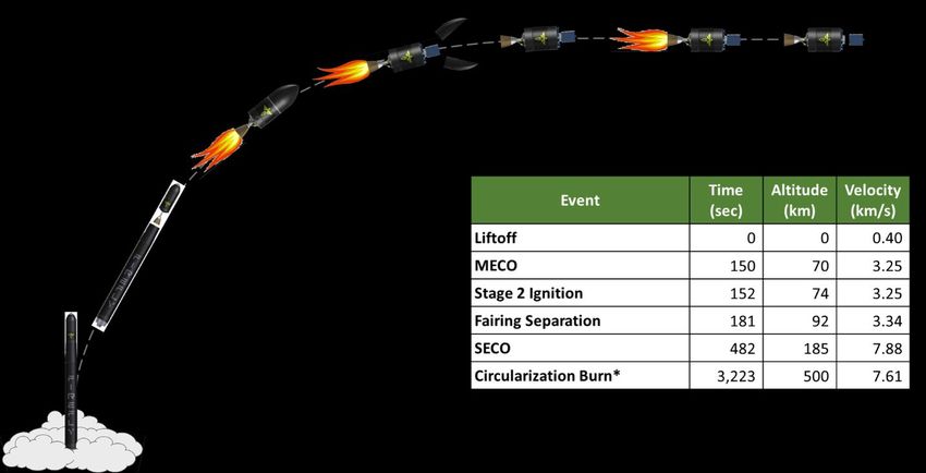
FF-0005001 - Alpha 1.0 Payload Users Guide Rev 01                                                               Page|2

CONTACT INFORMATION
Please contact Maureen Gannon with enquiries into the suitability of the Alpha Launch Vehicle for your
mission.

Maureen Gannon
Vice President, Business Development
Firefly Space Systems
1320 Arrow Point Drive
Cedar Park, TX 78613
Phone: 512-234-3700
Fax: 877-318-8560
Email: maureen@fireflyspace.com
Web: www.fireflyspace.com

       Intellectual Property Designation. This document contains technical data that is Firefly proprietary.
       Export Control Designation. This document does not contain technical data subject to ITAR/EAR restrictions.
       © 2015 Firefly Space Systems, Inc.
FF-0005001 - Alpha 1.0 Payload Users Guide Rev 01                                                               Page|3

REVISION HISTORY

     Revision                Date                          By                                     Notes
         1                July 2015                                                          Initial Release

       Intellectual Property Designation. This document contains technical data that is Firefly proprietary.
       Export Control Designation. This document does not contain technical data subject to ITAR/EAR restrictions.
       © 2015 Firefly Space Systems, Inc.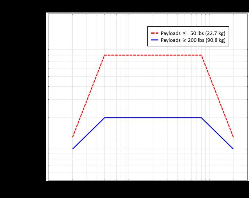
FF-0005001 - Alpha 1.0 Payload Users Guide Rev 01                                                                                     Page|4

TABLE OF CONTENTS
1     Introduction ..........................................................................................................................8
      1.1     Company Description.......................................................................................................... 8
      1.2     Alpha Vehicle Overview ...................................................................................................... 8
2     Alpha Performance Capabilities ............................................................................................ 10
      2.1     Orbit Delivery Capability ................................................................................................... 10
      2.2     Flight Sequence & Profile.................................................................................................. 10
      2.3     Payload Insertion Accuracy ............................................................................................... 12
3     Mission and Typical Program Overview ................................................................................ 12
      3.1     Planning & Preparation ..................................................................................................... 12
      3.2     Launch Campaign Timeline ............................................................................................... 12
      3.3     Payload Integration Operations ........................................................................................ 13
4     Payload Accommodation ..................................................................................................... 13
      4.1     Payload Fairing Available Volume..................................................................................... 13
      4.2     Payload Accommodation Scenarios.................................................................................. 14
      4.3     Payload Interfaces ............................................................................................................ 14
5     Payload Environments ......................................................................................................... 16
      5.1     Mechanical ........................................................................................................................ 16
      5.2     Thermal & Atmospheric .................................................................................................... 19
      5.3     Payload Environment – RF & EMC .................................................................................... 21
6     Payload Requirements ......................................................................................................... 22
      6.1     Primary Passenger Requirements ..................................................................................... 22
      6.2     Secondary/Auxiliary Passenger Requirements (including CubeSats) ............................... 23
      6.3     Documentation Requirements ......................................................................................... 25
      6.4     Evidence of Qualification & Acceptance ........................................................................... 25
      6.5     Safety Requirements......................................................................................................... 26
7     Launch Operations ............................................................................................................... 26
      7.1     Launch Control Organization ............................................................................................ 26
      7.2     Payload Transport to Launch Site ..................................................................................... 27
      7.3     Launch Site Facilities, Services and Provisions.................................................................. 27
8     Baseline Launch Offering ...................................................................................................... 29
9     Mission Programmatics & Timelines ..................................................................................... 30
10    Reference Documents .......................................................................................................... 31
Appendix 1.   Launch Site Facility Layout (Notional) ....................................................................... 32
Appendix 2.   Document Content Guidelines .................................................................................. 33

         Intellectual Property Designation. This document contains technical data that is Firefly proprietary.
         Export Control Designation. This document does not contain technical data subject to ITAR/EAR restrictions.
         © 2015 Firefly Space Systems, Inc.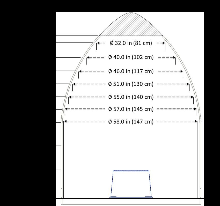
FF-0005001 - Alpha 1.0 Payload Users Guide Rev 01                                                                                                   Page|5

LIST OF FIGURES

Figure 1: Firefly Alpha Vehicle and Key Characteristics .................................................................................................9
Figure 2: Firefly Alpha Vehicle Axes Definitions ..........................................................................................................10
Figure 3: Firefly Alpha Performance to Various Inclinations and Altitudes .................................................................11
Figure 4: Typical Alpha Flight Profile ...........................................................................................................................11
Figure 5: Typical Launch Campaign Timeline ...............................................................................................................13
Figure 6: Firefly Alpha Fairing Volume .........................................................................................................................14
Figure 7: Payload to Alpha and GSE Wiring Diagram ...................................................................................................15
Figure 8: Random Vibration Test Levels – Values TBC .................................................................................................18
Figure 9: Expected Shock Levels During Payload Separation – Values TBC .................................................................19
Figure 10: Faring Internal Pressure Profile ..................................................................................................................21
Figure 11: Launch Control Organization ......................................................................................................................27

LIST OF TABLES
Table 1: Transportation & Handling Loads ..................................................................................................................17
Table 2: Quasi-static Flight Loads at Spacecraft/Launch Vehicle Interface .................................................................17
Table 3: Random Vibration Loads for Payloads 200 lbs (91 kg) and Larger – Values TBC ...........................................18
Table 4: Random Vibration Loads for Payloads 50 lbs (23 kg) and Smaller – Values TBC ...........................................18
Table 5: Expected Shock Values – Values TBC .............................................................................................................19
Table 6: Payload Environmental Conditioning.............................................................................................................20
Table 7: Alpha RF System Characteristics – Values TBD ..............................................................................................21
Table 8: Quasi-static Loading for Auxiliary and Secondary Payloads ..........................................................................24
Table 9: Typical Firefly Alpha Mission Timeline ...........................................................................................................31

          Intellectual Property Designation. This document contains technical data that is Firefly proprietary.
          Export Control Designation. This document does not contain technical data subject to ITAR/EAR restrictions.
          © 2015 Firefly Space Systems, Inc.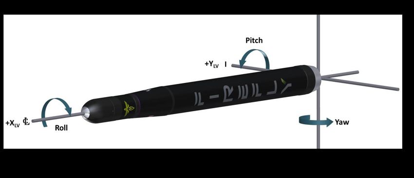
FF-0005001 - Alpha 1.0 Payload Users Guide Rev 01 Page|6
OVERVIEW AND PURPOSE OF DOCUMENT
Welcome to the Payload User Guide for the Firefly Alpha Launch Vehicle. The purpose of this document
is to provide summary information for preliminary mission planning purposes between the payload
customer and Firefly. This document provides the vehicle information to validate payload compatibility.
The Payload User Guide is structured into two main portions:
Sections 1 through 3 describe the Firefly organization and the characteristics and performances
of the Firefly Alpha Vehicle.
Sections 4 through 10 define interfaces, describe environmental conditions, and state the
requirements to be met by payloads.
DEFINITIONS AND ACRONYMS
Common Definitions
The following definitions apply when referred to in this document:
Term Definition
Ambient The surrounding environmental conditions such as pressure or temperature
Acronyms
ASD Acceleration Spectral Density
CAD Computer Aided Design
CCAFS Cape Canaveral Air Force Station
CFM Cubic Feet per Minute
CoG Centre of Gravity
EC Engine Controller
EGSE Electrical Ground Support Equipment
EMC Electro Magnetic Compatibility
EPS Electronic Power Sub-System
FE Finite Element
FPS Frames Per Second
Intellectual Property Designation. This document contains technical data that is Firefly proprietary.
Export Control Designation. This document does not contain technical data subject to ITAR/EAR restrictions.
© 2015 Firefly Space Systems, Inc.
FF-0005001 - Alpha 1.0 Payload Users Guide Rev 01                                                               Page|7

       GSE            Ground Support Equipment

       HD             High Definition

       HIF            Horizontal Integration Facility (Hangar)

       I-bay          Information Bay
       ICD            Interface Control Document

       IMU            Inertial Measurement Unit

       LEO            Low Earth Orbit

       LV             Launch Vehicle

       MGSE           Mechanical Ground Support Equipment

       OASPL          Overall Sound Pressure Level

       PAF            Payload Attach Fitting

       PCS            Probability of Command Shutdown

       PPF            Payload Processing Facility

       RF             Radio Frequency

       RIU            Remote Interface Unit

       RMS            Root Mean Square

       TBC            To Be Confirmed

       TBD            To Be Determined

       TBR            To Be Reviewed

       TLE            Two Line Element

       Intellectual Property Designation. This document contains technical data that is Firefly proprietary.
       Export Control Designation. This document does not contain technical data subject to ITAR/EAR restrictions.
       © 2015 Firefly Space Systems, Inc.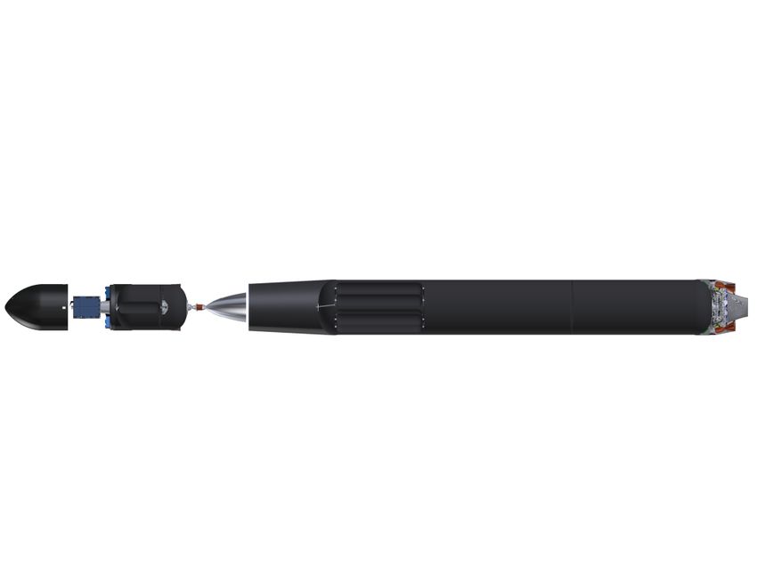
FF-0005001 - Alpha 1.0 Payload Users Guide Rev 01                                                               Page|8

1 INTRODUCTION
1.1 COMPANY DESCRIPTION
Firefly Space Systems is developing the Alpha launch vehicle to provide low-cost, high-frequency launch
capability for the rapidly growing and critically underserved small satellite industry.
Firefly’s simplest-soonest approach to technology selection will deliver game changing launch costs,
accessibility, and reliability for customers.
Firefly’s seasoned engineering team is comprised of industry-proven leaders with experience in both
building commercial launch vehicles as well as successful technology firms. Augmenting and rounding out
this team are passionate young minds from the country's top engineering schools. Each vehicle is
engineered with cross-industry design insights and leverages high Technology Readiness Level (TRL)
design elements to reduce risk and guarantee reliability. The technologies employed in our Alpha flagship
vehicle provide a clear pathway for future incremental improvements in vehicle capability.
This unique development approach aims for monthly rocket launches within 3 years and a reusable launch
vehicle within 5 years.

1.2 ALPHA VEHICLE OVERVIEW
Alpha is a two-stage launch vehicle capable of delivering 400 kg of payload to LEO. The first variant, Alpha
1.0, utilizes efficient technologies such as composite tanks, a plug cluster aerospike, and traditional bell
nozzle engines with hydrocarbon fuel. Alpha operations are highly streamlined, with all facets of design,
testing, and production located in central Texas.
Alpha will bring the following advantages to customers:
Availability
Firefly launch vehicles will be mass produced to the highest quality standards. Mass production enables
the ability to change the industry through regularly scheduled launches. Although every launch vehicle is
built to plan, payload attachment fittings can be adapted to specific customer needs.
Reliability
Firefly launch vehicles are built with reliability in mind. Separation events are kept to a minimum. There
are just 3: stage, fairing, and payload separation. Each launch vehicle will run through a regime of tests,
starting at the component level, up to a full stage test prior to transportation to the launch site.
Cost
Firefly launch vehicles give small satellite customers a tailored and dedicated launch service for a lower
all-in cost than a secondary/auxiliary launch. A complete vehicle may be purchased for $8M, which
includes a re-fly guarantee in the unlikely event of a launch failure. The standard offered payload interface
is also included in the price.

       Intellectual Property Designation. This document contains technical data that is Firefly proprietary.
       Export Control Designation. This document does not contain technical data subject to ITAR/EAR restrictions.
       © 2015 Firefly Space Systems, Inc.
FF-0005001 - Alpha 1.0 Payload Users Guide Rev 01 Page|9
Payload Segment
7.5 feet
Payload
200 kg to 500 km Sun Synchronous Orbit
Primary Payload (1x)
3U CubeSat Deployers (12x)
Payload Fairing Second Stage LOx Tank
Cold Gas Separation
Carbon Composite Second Stage Helium Tank
Second Stage
Second Stage Avionics
15.0 feet
KU, L, S Band Antennas
GPS/IMU Navigation
Two Redundant Flight Computers
Expandable 28V Power Bus
Second Stage Fuel Tank
28V Payload Power
Ethernet Payload Communication Line
Interstage
Stage Interface Structure Second Stage Engine
Houses Second Stage Engine FRE-1
Pusher-Mechanism Stage Separation LOx/RP-1
Carbon Composite Single Conventional Bell Nozzle
Thrust: 6,200 lbf
Isp: 325 seconds
First Stage Helium Tanks
First Stage LOx Tank
First Stage
54.8 feet
First Stage Avionics
First Stage Fuel Tank
Secondary Navigation IMU
Third Redundant Flight Computer
Expandable 28V Power Bus
First Stage Engine
FRE-2
LOx/RP-1
Plug Cluster Aerospike
12 Combustors
Thrust: 99,600 lbf (sea level)
Isp: 299 seconds (vac)
F IGURE 1: FIREFLY A LPHA VEHICLE AND KEY C HARACTERISTICS
Intellectual Property Designation. This document contains technical data that is Firefly proprietary.
Export Control Designation. This document does not contain technical data subject to ITAR/EAR restrictions.
© 2015 Firefly Space Systems, Inc.FF-0005001 - Alpha 1.0 Payload Users Guide Rev 01 P a g e | 10
1.2.1 Vehicle Axes Definitions
Figure 2 shows the definition of the Axes for the Firefly Alpha Vehicle. As is the case with most launch
vehicles, the X axis is the roll axis for the vehicle, and therefore the vertical axis for any vertically mounted
passenger satellite. The axes definitions in Figure 2 are used throughout this user guide to specify payload
environments, loads and test requirements.
F IGURE 2: FIREFLY A LPHA VEHICLE A XES DEFINITIONS
2 ALPHA PERFORMANCE CAPABILITIES
2.1 ORBIT DELIVERY CAPABILITY
The performance capabilities of the Firefly Alpha vehicle are detailed in the figures and tables below.
Alpha can accommodate a wide range of Payload requirements and our team can provide innovative
performance trades to meet our customer’s needs.
Figure 3 shows orbit delivery performance for inclinations ranging from Due East to Polar and Sun
Synchronous Orbits. All orbits were calculated using the Equator as the launch location. A small (10%)
variation in payload delivery can be expected depending on which launch site is utilized.
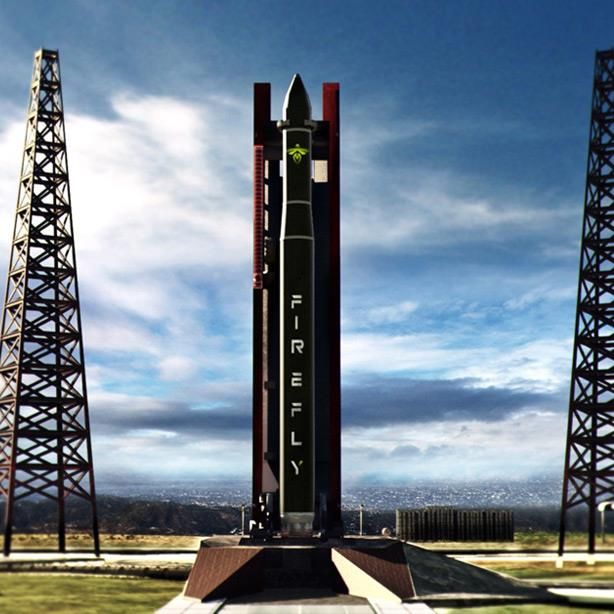
2.2 FLIGHT SEQUENCE & PROFILE
The Firefly Alpha flight profile is depicted in 4. Most missions will follow a profile similar to that shown in
4, though the times at which key events occur may vary slightly. For direct insertion missions, payload
separation will occur approximately 500 seconds after liftoff. For multi-manifested missions and/or those
requiring higher orbits, the Alpha second stage will first insert into a low elliptical transfer orbit, coast to
apogee, and then initiate a second burn to circularize into the final orbit. In this case, primary payload
separation will occur approximately 3000 seconds after liftoff.
Intellectual Property Designation. This document contains technical data that is Firefly proprietary.
Export Control Designation. This document does not contain technical data subject to ITAR/EAR restrictions.
© 2015 Firefly Space Systems, Inc.FF-0005001 - Alpha 1.0 Payload Users Guide Rev 01 P a g e | 11
F IGURE 3: FIREFLY A LPHA P ERFORMANCE TO VARIOUS INCLINATIONS AND A LTITUDES
F IGURE 4: T YPICAL A LPHA FLIGHT PROFILE
Intellectual Property Designation. This document contains technical data that is Firefly proprietary.
Export Control Designation. This document does not contain technical data subject to ITAR/EAR restrictions.
© 2015 Firefly Space Systems, Inc.FF-0005001 - Alpha 1.0 Payload Users Guide Rev 01 P a g e | 12
2.3 PAYLOAD INSERTION ACCURACY
The second stage of the Firefly Alpha vehicle incorporates a redundant inertial navigation control module
to provide precise pointing and orbit insertion.
For a second-stage probability of command shutdown (PCS) of 99.7%, the typical three-sigma (3σ)
dispersions for a two-stage mission to low-earth orbit are:
• Perigee altitude: ± 5 km (TBC)
• Apogee altitude: ± 5 km (TBC)
• Orbit inclination: ± 0.05 deg (TBC)
3 MISSION AND TYPICAL PROGRAM OVERVIEW
3.1 PLANNING & PREPARATION
3.1.1 Initial Contact
Initial contact should be made via the contact details included at the front of this document. Each
customer will be assigned a primary point of contact (Mission Manager) who will remain as the primary
interface between Firefly and the customer throughout the entire mission planning and execution
process.
3.1.2 Meetings & Communications
Customers can expect transparency and open communication throughout the entire process, with regular
status reports from their Mission Manager.
3.1.3 Fit Checks
One fit check meeting is foreseen during the mission preparation phase, typically to take place at Firefly’s
integration facilities. This will be combined with a meeting to finalize the payload to launch vehicle ICD.
Activities and objectives of the Fit Check are as follows:
To assemble a full up, mass and volume representative model of the entire payload composite,
including all payloads (in the event of multi-manifested launch configurations) and separation
systems and adapters
To validate the mechanical and electrical interfaces
Where possible, to validate the operation of all separation systems.
The customer will be expected to provide a representative volume and mass dummy of their payload
including the expected mechanical and electrical interfaces.
3.2 LAUNCH CAMPAIGN TIMELINE
Figure 5 gives an overview of the activities in a typical launch campaign, including the launch specific
activities, payload specific activities and the integrated activities. A typical expected overall launch
campaign duration is 3 weeks. 7-10 days are typically assigned to payload checkout and miscellaneous
autonomous payload operations, and an additional 7-10 days are typically required for payload to
launcher integration activities and final launcher preparation activities (including fairing closure, transport
to launch pad, and launcher erection).
Intellectual Property Designation. This document contains technical data that is Firefly proprietary.
Export Control Designation. This document does not contain technical data subject to ITAR/EAR restrictions.
© 2015 Firefly Space Systems, Inc.FF-0005001 - Alpha 1.0 Payload Users Guide Rev 01 P a g e | 13
F IGURE 5: T YPICAL L AUNCH CAMPAIGN TIMELINE
3.3 PAYLOAD INTEGRATION OPERATIONS
Payloads will be processed in an ISO 8 (Class 100K FED-STD-209E) clean room environment. They will be
mated to the Payload Attachment Fitting (PAF) and encapsulated by the payload fairing in the vertical
position. The encapsulated payload will then be rotated to a horizontal orientation by means of a break-
over fixture. The payload fairing will be mated to the launch vehicle in the horizontal position. The payload
will be in a horizontal, cantilevered position until the launch vehicle is rolled out to the pad and raised to
the vertical position. Additional details about this process can be found in Section 7.3.
3.3.1 CubeSats
For customers with 3U CubeSats, a CubeSat Deployment Canister will be sent to the customer for loading
and shipment back to the Firefly facility. Customers may also complete this portion of the integration
process at the Firefly facility in a shared use secondary payload clean room (ISO 8 / Class 100K FED-STD-
209E).
To maximize secondary payload capacity, 1U and 2U CubeSats from multiple customers may be integrated
into a single 3U CubeSat Deployment Canister. In these situations, integration must occur at the Firefly
facility.
Customers with 6U, 12U, or clusters of CubeSats should contact Firefly to discuss other possible
integration options.
4 PAYLOAD ACCOMMODATION
4.1 PAYLOAD FAIRING AVAILABLE VOLUME
The payload is protected by a fairing that shields it from aerodynamic buffeting and heating while in the
lower atmosphere. The fairing is a carbon fiber composite structure with a nominal outer diameter of 5ft.
The maximum useable internal diameter is shown in Figure 6. Acoustic foam will be used to reduce the
acoustic environment within the payload fairing.
Intellectual Property Designation. This document contains technical data that is Firefly proprietary.
Export Control Designation. This document does not contain technical data subject to ITAR/EAR restrictions.
© 2015 Firefly Space Systems, Inc.FF-0005001 - Alpha 1.0 Payload Users Guide Rev 01 P a g e | 14
F IGURE 6: FIREFLY A LPHA F AIRING VOLUME
4.2 PAYLOAD ACCOMMODATION SCENARIOS
Two Initial Payload accommodation scenarios are defined for Payload Accommodation:
Single (Primary Only) payload, and
Primary payload plus secondary/auxiliary payloads (including CubeSats)
Requirements and constraints for Primary and Secondary payloads may be slightly different.
4.2.1 Payload Integration Access and Stay-out Zones
Within the payload fairing and in the vicinity of the payload adapters and interfaces, there are likely to be
some stay out zones (associated with Firefly equipment and fixtures) where payloads cannot infringe.
Details of stay-out zones will be included in later versions of this guide and in any case will be negotiable
and flexible where possible.
4.3 PAYLOAD INTERFACES
The Firefly Alpha vehicle features a number of standard mechanical and electrical interfaces in order to
accommodate typical small satellite interfacing requirements and characteristics. The emphasis is on
interface simplicity and robustness, in line with the overall Firefly Approach.
Intellectual Property Designation. This document contains technical data that is Firefly proprietary.
Export Control Designation. This document does not contain technical data subject to ITAR/EAR restrictions.
© 2015 Firefly Space Systems, Inc.FF-0005001 - Alpha 1.0 Payload Users Guide Rev 01 P a g e | 15
4.3.1 Mechanical Interfaces & Separation Systems
Firefly Alpha offers a number of common industry mechanical interface arrangements for payloads, with
most common attachment patterns and bolt circles accommodated.
The standard Payload Attachment Fitting (PAF) is designed to interface with a 15-inch (“ESPA” interface)
Lightband or clamp band separation system. The interface is (24x) 1/4”-28 bolts evenly spaced around a
15 inch bolt circle diameter.
The most commonly used small satellite separation systems are all accommodated, including:
Dassault ASAP 5 (see Reference 1)
Planetary Systems Lightband (see Reference 2)
Ruag Clamp Band Separation Systems (see Reference 3)
ISIPOD CubeSat Deployer (see Reference 4)
Per customer request, the PAF design can be modified to accommodate satellite separation systems of
diameters ranging from 8 inches up to 24 inches (“ESPA Grande” interface). Requests for accommodation
of any non-standard payload interface should be made early in the mission planning process.
4.3.2 Electrical Interface
The Alpha Launch Vehicle provides a set of standard payload electrical interfaces in addition to a rich set
of optional but prequalified interfaces. Other custom configurations can be accommodated but may
require development NRE and qualification cost and schedule. Connector type and pinouts for the
payload will be specified during the spacecraft integration process. This connection will provide power,
necessary communication lines, and separation detection systems as illustrated in Figure 7.
All payload interfaces to the Alpha PAF must be electrically conductive with sheet resistance less than 0.1
Ohms per unit area. This interface will be auto verified during payload integration. It is the customer’s
responsibility to ensure this requirement is met prior to shipment of the payload to the launch site.
F IGURE 7: P AYLOAD TO ALPHA AND GSE WIRING D IAGRAM
Intellectual Property Designation. This document contains technical data that is Firefly proprietary.
Export Control Designation. This document does not contain technical data subject to ITAR/EAR restrictions.
© 2015 Firefly Space Systems, Inc.FF-0005001 - Alpha 1.0 Payload Users Guide Rev 01 P a g e | 16
4.3.3 Spacecraft Power
The spacecraft is provided access to a 28V regulated voltage source that is current limited to 5 amps. This
power is sourced from the Alpha EGSE through Alpha’s Electrical Power System (EPS), and can be used to
charge spacecraft batteries or perform other system functions prior to launch. Please note that spacecraft
must contain their own voltage monitoring and charging circuitry if this power source is to be used for
battery charging. The Alpha EPS does not perform those functions. This bus will be disconnected prior to
launch and the spacecraft should power down at that time. Higher currents are available as an option but
all sources are limited maximum-current voltage sources.
Customers with CubeSat payloads will have the opportunity to manually check battery voltage and charge
if needed prior to integration with the CubeSat Deployer. By default, charging or other diagnostic checks
will not be available once the deployer is mated to the vehicle.
Customers who opt to integrate their CubeSat with the deployer at their own facility and ship the
integrated assembly to Firefly will not have the opportunity to check battery state before the deployer is
mated to the vehicle.
Contact Firefly early in the mission planning process if your mission requires special accommodations not
listed above.
4.3.4 Spacecraft to Ground Data transfer
In the majority of cases it is not expected that data connections will be required between the spacecraft
and ground following payload integration. The baseline offering requires all payloads to be in a powered
off (inactive) state during launch; Therefore, no data transfer between spacecraft and GSE will be possible.
In cases where data transfer is required by the customer, Firefly can provide optional limited-
priority/bandwidth channels through Alpha’s auxiliary command and telemetry system. Firefly can
provide a standard set of serial commands (115200 baud RS-485 or UART) to the payload indicating
affirmative Stage 2 separation, fairing separation, and Stage 2 engine burnout prior to the payload
separation command. Alpha can also provide pass through cables for payload communication to payload
electrical ground support equipment. Pass-through systems are compatible with 10/100/1000Base-TX
communication.
Please contact Firefly early in the mission planning process if you intend to be powered on during launch,
as additional time and cost implications are likely.
5 PAYLOAD ENVIRONMENTS
The environment and loads that payloads will be subjected to during launch on the Firefly Alpha vehicle
are described in this section.
5.1 MECHANICAL
5.1.1 Transportation and Handling Loads
Table 1 shows the maximum transportation and handling loads anticipated in payload design. For
additional information, see Reference 5.
Intellectual Property Designation. This document contains technical data that is Firefly proprietary.
Export Control Designation. This document does not contain technical data subject to ITAR/EAR restrictions.
© 2015 Firefly Space Systems, Inc.FF-0005001 - Alpha 1.0 Payload Users Guide Rev 01 P a g e | 17
Transportation/Handling Loads
Event Axial Load (x), g Lateral Load (y), g Vertical Load (z), g
Ground Shipment ± 3.5 (TBC) ± 2.0 (TBC) ± 6.0 (TBC)
Ground Handling ± 2.0 (TBC) ± 1.0 (TBC) ± 1.0 (TBC)
Break-over and Transport Erector ± 1.0 (TBC) ± 1.0 (TBC) ± 2.0 (TBC)
Roll-out
T ABLE 1: T RANSPORTATION & H ANDLING LOADS
5.1.2 Flight Loads – Quasi-Static
Table 2 shows the maximum quasi-static loads to be expected at the payload/launch vehicle interface
during flight.
Quasi-Static Loads During Flight
Event Axial Load (x), g Lateral Load (y,z), g
Liftoff 1.3 ±0.3
Max qα 1.8 ±0.3
Stage 1 Engine Cutoff 6.0 ± 0.3
Stage 2 Ignition 0.8 ± 0.3
Stage 2 Engine Cutoff 3.7 ± 0.3
T ABLE 2: QUASI- STATIC FLIGHT LOADS AT SPACECRAFT/LAUNCH VEHICLE I NTERFACE
5.1.3 Flight Loads - Random Vibration
During launch, payloads will be subjected to a random vibration environment due to a combination of
engine vibrations, vehicle structural modes, and aerodynamic buffeting. The intensity of these vibrations
is highly dependent on payload mass and the interface between the payload and the launch vehicle.
Spacecraft with masses above 200 lbs (91 kg) – i.e. primary payloads – shall design to the blue curve
presented in Figure 8, with detailed values provided in Table 3. These levels were generated based on
random vibration acceptance test levels provided in GSFC-STD-7000A (see Reference 6). ASD levels will
be updated as data from further analysis and testing of the Alpha vehicle becomes available.
Spacecraft with masses below 50 lbs (23 kg) – i.e. secondary payloads, including CubeSats – shall design
to the red curve presented in Figure 8, with detailed values provided in Table 4. These levels were
generated based on random vibration acceptance test levels provided in GSFC-STD-7000A (see Reference
6). ASD levels will be updated as data from further analysis and testing of the Alpha vehicle becomes
available.
Please contact Firefly for payload-specific ASD values if your spacecraft has sensitive equipment (e.g.
optics) or has a mass in the range of 50-200 lbs (23-91 kg).
Intellectual Property Designation. This document contains technical data that is Firefly proprietary.
Export Control Designation. This document does not contain technical data subject to ITAR/EAR restrictions.
© 2015 Firefly Space Systems, Inc.FF-0005001 - Alpha 1.0 Payload Users Guide Rev 01 P a g e | 18
F IGURE 8: R ANDOM VIBRATION TEST LEVELS – VALUES TBC
Random Vibration Loads During Flight
For Payloads 200 lbs (91 kg) and Larger
Frequency ASD Level (g2/Hz)
20 Hz 0.01
20-50 Hz +2.28 dB/oct
50-800 Hz 0.02
800-2000 Hz -2.28 dB/oct
2000 Hz 0.01
Overall 4.86 GRMS
T ABLE 3: R ANDOM VIBRATION LOADS FOR P AYLOADS 200 LBS (91 KG) AND L ARGER – V ALUES TBC
Random Vibration Loads During Flight
For Payloads 50 lbs (23 kg) and Smaller
Frequency ASD Level (g2/Hz)
20 Hz 0.013
20-50 Hz +6 dB/oct
50-800 Hz 0.08
800-2000 Hz -6 dB/oct
2000 Hz 0.013
Overall 10.0 GRMS
T ABLE 4: R ANDOM VIBRATION LOADS FOR P AYLOADS 50 LBS (23 KG) AND SMALLER – VALUES TBC
Intellectual Property Designation. This document contains technical data that is Firefly proprietary.
Export Control Designation. This document does not contain technical data subject to ITAR/EAR restrictions.
© 2015 Firefly Space Systems, Inc.FF-0005001 - Alpha 1.0 Payload Users Guide Rev 01 P a g e | 19 5.1.4 Flight Loads – Acoustic The maximum acoustic environment the Payload sees is at liftoff and through transonic flight. The acoustic environment for the Payload in a blanketed fairing is still TBD. It is expected to meet an Overall Sound Pressure Level (OASPL) of
FF-0005001 - Alpha 1.0 Payload Users Guide Rev 01                                                                   P a g e | 20

components. A trickle nitrogen (MIL-PRF-27401F, Type 1, Grade B purge) can be provided for specific
bagged sensors while inside the processing facility prior to and after encapsulation. After encapsulation a
trickle purge line to a sensor bag can be accommodated through a strategically placed fairing access panel
opening. Both of these trickle purges will be controlled by customer supplied equipment. Source nitrogen
can be provided by facility systems or K-bottles. After roll-out, a continuous supply of clean air is provided
at a typical environment range as stated in the table below. After roll-out and prior to the vertical position
movement, the bag would be removed from the sensor and the flight access panel installed on the fairing.
A nitrogen purge can be provided through the payload air-distribution umbilical ducting while at the
launch pad. The air distribution umbilical is attached to the fairing by means of locking mechanism that is
pulled away by a lanyard at lift off. As the umbilical is pulled away from the fairing the spring loaded access
door automatically closes.

                                                 Payload Environmental Conditioning
                Location                    Temperature    Relative Humidity        Flow Rate        Filtration     Hydrocarbons

                  Payload Integration         75F ± 5F                           900-1500 CFM
  Firefly HIF                                                35% - 50% ± 5%                        Class 100,000     15ppm max
                        Facility            23.89C ± 2.8C                       25.5-42.5 m³/min

                                              75F ± 5F                            180-240 CFM
  Firefly HIF     Fairing Encapsulated                       35% - 50% ± 5%                        Class 100,000     15ppm max
                                            23.89C ± 2.8C                        5.1-6.8 m³/min

 Firefly Pad    Payload Fairing Roll Out    Not Controlled   Not Controlled      Not Controlled    Not Controlled   Not Controlled

                Payload Fairing at Launch     75F ± 5F                            180-240 CFM
 Firefly Pad                                                 35% - 50% ± 5%                        Class 100,000     15ppm max
                          Pad               23.89C ± 2.8C                        5.1-6.8 m³/min

                                     T ABLE 6: P AYLOAD E NVIRONMENTAL C ONDITIONING

5.2.2      Fairing Thermal Environment
Upon Payload encapsulation, air-conditioning is provided at a typical temperature range as stated in
Section 5.2.1, depending on mission requirements.
The Alpha fairing is made up of carbon composite with an emissivity of (TBD). The acoustic foam can
provide a relatively cool radiation environment by effectively shielding the payload from ascent heating
in blanketed areas.

5.2.3      On Orbit Thermal Environment
As most Firefly missions are expected to be of short durations (for delivery in to Low Earth orbits), active
thermal control or heating of payloads is not foreseen. During coast periods, the launch vehicle can be
oriented to meet specific sun angle requirements if required. Active thermal control and payload heating
may be able to be accommodated as an optional extra (see Section 8 for more details).

5.2.4      Fairing Internal Pressure
As the Alpha vehicle ascends through the atmosphere, the fairing will be vented through one way vents
at the bottom of the fairing. The maximum expected pressure decay rate inside the fairing compartment
is -0.24 psi/second. The internal pressure and depressurization rates are illustrated as functions of time in
Figure 10.

         Intellectual Property Designation. This document contains technical data that is Firefly proprietary.
         Export Control Designation. This document does not contain technical data subject to ITAR/EAR restrictions.
         © 2015 Firefly Space Systems, Inc.
FF-0005001 - Alpha 1.0 Payload Users Guide Rev 01 P a g e | 21
F IGURE 10: F ARING I NTERNAL P RESSURE PROFILE
5.3 PAYLOAD ENVIRONMENT – RF & EMC
5.3.1.1 Radio Frequency Environment
The Alpha vehicle’s payload fairing attenuates RF transmissions during launch pad operations, flight
ascent, and up to the point of fairing separation. After fairing separation, S-band transmission will not
exceed (TBD) dBm at the Center of Gravity of the fairing. Ku-Band transmissions will not exceed (TBD)
dBm. It is recommended that payloads are powered off during launch to reduce the risk of damage caused
by RF interference. Payload RF characteristics shall be designed such that there is no interference with
the Alpha vehicle RF systems detailed in Table 7. Alpha customers must ensure that any payload
component or material constituents that are sensitive to RF transmissions are compatible with the
electromagnetic environment of the Alpha vehicle.
Payload Environmental Conditioning
Function Stage 1 TLM Stage 2 TLM Alpha TLM GPS
Role Transmit Transmit Transmit Receive
Band S-Band S-Band Ku-Band L-Band
Frequency (MHz) TBD TBD TBD TBD
Bandwidth TBD TBD TBD TBD
Power Output TBD TBD TBD TBD
Sensitivity TBD TBD TBD TBD
Modulation TBD TBD TBD TBD
T ABLE 7: A LPHA RF SYSTEM C HARACTERISTICS – VALUES TBD
Intellectual Property Designation. This document contains technical data that is Firefly proprietary.
Export Control Designation. This document does not contain technical data subject to ITAR/EAR restrictions.
© 2015 Firefly Space Systems, Inc.FF-0005001 - Alpha 1.0 Payload Users Guide Rev 01 P a g e | 22
6 PAYLOAD REQUIREMENTS
This section details the requirements to be satisfied for any payload on the Firefly Alpha Vehicle. The
requirements can be classified as follows:
Demonstrated (test) evidence of compatibility with the loads and environments generated by the
Firefly Alpha Vehicle.
Demonstrated (test) evidence of compatibility with the Firefly Alpha vehicles’ electrical and
communications systems
Documentary evidence of compatibility of mechanical and electrical interfaces
In keeping with the overall goals of the Firefly service, it is intended that evidence be as succinct as
possible. Guidelines on what is considered acceptable evidence is included in Appendix 2.
Requirements for Primary and Secondary/Auxiliary payloads are different for some parameters.
6.1 PRIMARY PASSENGER REQUIREMENTS
6.1.1 Resonances & First Natural Frequency
The Primary Passenger must provide evidence of the 1st lateral resonant frequency being above 20 Hz
(TBC).
The Primary Passenger must provide evidence of the 1st axial resonant frequency being above 25 Hz
(TBC).
Both of these requirements refer to the Firefly Alpha vehicle definitions as show in Section 1.2.1.
6.1.2 Quasi-static and/or Sine Vibration Loading
The Primary Passenger must provide evidence that the payload is robust and will not suffer mechanical
failure under the loadings specified in Table 2, with positive margin.
6.1.3 Random Vibration
The Primary Passenger must provide evidence that the payload is robust and will not suffer mechanical
failure under the loadings specified in Table 3, with +3 dB margin. Test duration shall be 2 minutes, per
Reference 6.
6.1.4 Acoustic Vibration
Should the primary passenger choose to design and qualify/accept their design against the acoustic load
environment (as may be expected for larger satellites), the passenger must provide evidence that the
payload is robust and will not suffer mechanical failure under the loadings specified in Section 5.1.4, with
positive margin.
6.1.5 Notching
Reduction of the vibration input amplitude at certain resonance frequencies (i.e. notching) may be
possible for the primary passenger, but cannot be guaranteed. Any notching requirements or preferences
should be communicated to Firefly as early as possible in the mission planning process.
Intellectual Property Designation. This document contains technical data that is Firefly proprietary.
Export Control Designation. This document does not contain technical data subject to ITAR/EAR restrictions.
© 2015 Firefly Space Systems, Inc.FF-0005001 - Alpha 1.0 Payload Users Guide Rev 01 P a g e | 23
6.1.6 Mass Properties
The required position of the Primary Passengers Center of Gravity (CoG), relative to the plane of
separation, is as follows: (this assumes that the primary passenger is mounted centrally, i.e. with its
vertical axis aligned with the launch vehicles roll (x) axis:
Offset of CoG from Y & Z axis: < 2 in (50 mm) (TBR)
Offset of CoG from separation system interface plane: < 18 in (457mm) (TBR)
6.1.7 Grounding, EMC & RF Transmissions
It is assumed that all payloads will be powered off during launch (in line with the Firefly baseline launch
offering), and therefore will not be emitting any signals or radio frequency noise during the launch phase.
Payloads that request to be powered on during launch will be required to provide evidence of a spacecraft
level EMC test which shows EM compatibility with the Firefly vehicle, assuring that any payload operations
during launch cannot interfere with Firefly’s Avionics & Flight Systems.
All payloads (including those which will be powered off) are required to show compliance to the Firefly
EMC specification to ensure that post-separation operations of the launch vehicle upper stage are not
compromised by the payload(s).
All payload interfaces to the Alpha PAF must be electrically conductive to less than 0.1 Ohms per unit area.
This interface will be auto verified during payload integration. It is the customer’s responsibility to ensure
this requirement is met prior to shipment of the payload to the launch site.
6.1.8 Numerical & Computer Models
In order for Firefly to carry out its mission analysis and design for the primary passenger, the following
numerical and/or computer models of the primary passenger spacecraft will be required:
A computer aided design (CAD) model, in STEP (*.stp or *.step) or Parasolid (*.x_t) format. The
CAD model supplied should include accurate representations of the external characteristics and
features of the spacecraft, including all appendages, and the separation system.
A Finite Element (FE) model of the spacecraft, in ANSYS Workbench Project Archive (*.wbpz),
Femap Neutral (*.neu, version 11.1 or older) or NASTRAN input (*.nas or *.bdf) format. The FE
model should accurately represent the spacecraft’s stiffness and mass properties, contain all
relevant material/connection property definitions, and should ideally be simplified.
For the timing of model delivery requirements within the mission schedule, please refer to Section 9.
6.1.9 Mass Dummy
A mass representative dummy of the primary passenger spacecraft will be required for the fit check. This
mass dummy should ideally be mass and volume representative and should have a representative launch
vehicle interfaces fitted. For the timing of model delivery requirements within the mission schedule,
please refer to Section 9.
6.2 SECONDARY/AUXILIARY PASSENGER REQUIREMENTS (INCLUDING CUBESATS)
Requirements for Secondary/Auxiliary passengers are different from those for primary passengers for
some parameters.
Intellectual Property Designation. This document contains technical data that is Firefly proprietary.
Export Control Designation. This document does not contain technical data subject to ITAR/EAR restrictions.
© 2015 Firefly Space Systems, Inc.FF-0005001 - Alpha 1.0 Payload Users Guide Rev 01 P a g e | 24
6.2.1 Resonances & First Natural Frequency
Secondary and Auxiliary Passengers must provide evidence of the 1st lateral resonant frequency being
above 50Hz (TBD)
Secondary and Auxiliary Passengers must provide evidence of the 1st axial resonant frequency being
above 100 Hz (TBD)
Both of these requirements refer to the Firefly Alpha vehicle definitions as show in Section 1.2.1.
6.2.2 Quasi-static and/or Sine Vibration Loading
The Primary Passenger must provide evidence that the payload is robust and will not suffer mechanical
failure under the loadings specified in Table 8, with positive margin.
Quasi-Static Loads for Auxiliary Passengers
Parameter Axial Load (x), g Lateral Load (y,z), g
Quasi-Static Loads 10 TBC ±2 TBC
T ABLE 8: QUASI- STATIC LOADING FOR A UXILIARY AND SECONDARY P AYLOADS
6.2.3 Random Vibration
Secondary payloads must also provide evidence that the payload is robust and will not suffer mechanical
failure under the loadings specified in Table 4, with +3 dB margin. Test duration shall be 2 minutes, per
Reference 6.
6.2.4 Notching
Reduction of the vibration input amplitude at certain resonance frequencies (i.e. notching) will not be
possible for Secondary and Auxiliary Passengers.
6.2.5 Mass Properties
Secondary payloads must adhere to the following requirements.
CubeSats shall comply with the requirements stated in the CubeSat Design Specification, Rev 13
[6].
1U CubeSats shall not exceed a mass of 1.33 kg.
3U CubeSats shall not exceed a mass of 4.0 kg. (TBR)
6U CubeSats shall not exceed a mass of 10.0 kg. (TBR)
Actuation of all deployment mechanisms such as booms, antennas, and solar panels shall wait a
minimum of 30 minutes after the CubeSat is deployed from the vehicle.
For individual CubeSats, Firefly will provide the dispenser. Larger CubeSat masses may be evaluated on a
mission by mission basis. Customers planning to supply their own deployment canisters should contact
Firefly as early as possible in the mission planning process.
There are no strict requirements for CoG positioning on the secondary payloads, as they are expected to
be arranged as a whole within the payload space by Firefly to achieve optimal mass distribution. Measured
mass properties of all payloads must be communicated to Firefly in accordance with the mission timelines
identified in Section 9.
Intellectual Property Designation. This document contains technical data that is Firefly proprietary.
Export Control Designation. This document does not contain technical data subject to ITAR/EAR restrictions.
© 2015 Firefly Space Systems, Inc.FF-0005001 - Alpha 1.0 Payload Users Guide Rev 01 P a g e | 25
6.2.6 Grounding, EMC & RF Transmissions
It is assumed that all payloads will be powered off during launch (in line with the Firefly baseline launch
offering), and therefore will not be emitting any signals or radio frequency noise during the launch phase.
Auxiliary and Secondary Payloads cannot be powered on during launch.
Secondary payloads are required to follow the same grounding and EMC compliance as primary payloads,
as detailed in Section 6.1.7.
6.2.7 Numerical & Computer Models
In order for Firefly to carry out its mission analysis and design for the primary passenger, the following
numerical and/or computer models of the auxiliary and secondary passenger spacecraft will be required:
A computer aided design (CAD) model, in STEP (*.stp or *.step) or Parasolid (*.x_t) format. The
CAD model supplied should include accurate representations of the external characteristics and
features of the spacecraft, including all appendages, and the separation system.
For the timing of model delivery requirements within the mission schedule, please refer to Section 9 of
this user guide.
6.2.8 Mass Dummies
A mass representative dummy of each payload shall be provided by each customer. For secondary payload
providers, this model will be retained until after launch, and will be returned by Firefly within 3 months
of launch. Firefly reserve the right to launch mass dummies of secondary payloads if delivery of Flight
Model Payloads is delayed for periods in excess of those comparable with primary payload requirements.
6.3 DOCUMENTATION REQUIREMENTS
Firefly’s philosophy is to keep documentation to a minimum and limited to that which is absolutely
required in order to execute a mission successfully and safely.
It is expected that most information will be captured in a single document, the master Launch Vehicle to
Spacecraft Interface Control Document (ICD). This should include details of all interfaces (mechanical,
electrical and other) and capture all information needed to describe the mission, interfaces and
interactions between launch vehicle and satellite.
Additional documentation may be required within the Safety Package and Qualification/Acceptance
evidence packages. These are described in Appendix 2.
6.4 EVIDENCE OF QUALIFICATION & ACCEPTANCE
Prior to the acceptance of all passengers, evidence must be provided to show that the requirements
identified in Sections 6.1 and 6.2. Data to be provided is expected to include:
Plots & Data from Spacecraft Flight Model or Qualification Model Mechanical Tests
RF/ EMC Tests Results
Configuration/version controlled source files for test results, etc., are preferred as evidence for the above.
In some cases, Firefly personnel may ask to be present for certain spacecraft qualification or acceptance
tests.
Intellectual Property Designation. This document contains technical data that is Firefly proprietary.
Export Control Designation. This document does not contain technical data subject to ITAR/EAR restrictions.
© 2015 Firefly Space Systems, Inc.FF-0005001 - Alpha 1.0 Payload Users Guide Rev 01 P a g e | 26
6.5 SAFETY REQUIREMENTS
At this time, prior to a final decision on a launch site location, Firefly suggests that customers meet the
requirements in AFSPCMAN 91-710, Range Safety User Requirements (see Reference 7) when designing
flight and ground systems. 91-710 contains requirements for mechanical, electrical, fluid system,
ordnance and RF design. It also contains requirements for ground handling and lifting hardware. Firefly
can assist customers in determining if their current designs meet the requirements in 91-710.
6.5.1 Spacecraft Batteries
Spacecraft batteries must not be allowed to overcharge excessively to the point where an explosion risk
arises.
6.5.2 Pressure Vessels
Spacecraft containing pressure vessels shall comply with the safety standards specified in ATR-
2005(5128)-1, Operational Guidelines for Spaceflight Pressure Vessels (see Reference 8).
6.5.3 Pyrotechnic and Explosive Devices
The standard baseline launch and launch services offering assumes that no pyrotechnic devices are
present on the payload(s). Customers planning to include pyrotechnic devices should contact Firefly as
early as possible in the mission planning process.
6.5.4 Ground Support Equipment
All ground support equipment (GSE) shall be safety tested with test reports available for review upon
request. Electrical GSE should include safety measures which allow spacecraft power to be cut in case of
emergency, and to prevent overcharging of spacecraft batteries. Lifting fixtures should be clearly marked
with proof load limits. Propulsion system GSE should include vent valves that will automatically activate
to prevent over pressurization.
7 LAUNCH OPERATIONS
7.1 LAUNCH CONTROL ORGANIZATION
Figure 11 shows the expected launch control organization and associated roles. The primary interface for
the customer remains a dedicated mission/project manager who will interface directly to the customer’s
project manager and the Firefly Mission Director.
Intellectual Property Designation. This document contains technical data that is Firefly proprietary.
Export Control Designation. This document does not contain technical data subject to ITAR/EAR restrictions.
© 2015 Firefly Space Systems, Inc.FF-0005001 - Alpha 1.0 Payload Users Guide Rev 01 P a g e | 27
Mission Director
(MD)
Launch Director Mission Flight
(LD) Control Officer
(MFCO)
Operations Safety
Launch Conductor Manager
Pad Supervisor Payload Manager
(LC) (OSM)
Launch Vehicle Payload Support
Support Consoles Consoles
Payload Customer
F IGURE 11: L AUNCH C ONTROL O RGANIZATION
7.2 PAYLOAD TRANSPORT TO LAUNCH SITE
Firefly Mission Managers will work with customers to coordinate transportation of payloads from the
pickup location (customer facility, airport, railway station, etc.) to the Firefly integration facility.
7.3 LAUNCH SITE FACILITIES, SERVICES AND PROVISIONS
7.3.1 Payload Processing & Checkout
The payload arrives at the Firefly PPF and is lifted from the transportation carrier by fork truck or overhead
crane located within the airlock. The satellite shipping container is wiped down prior to being relocated
into the clean room area, which will provide a minimum processing area of 324ft². The satellite will be
removed from the shipping container with an overhead crane and mated to the PAF/separation device.
Once the payload is fully assembled, checked out, and (if required) fueled, it will be encapsulated by the
fairing.
7.3.2 Encapsulation
After the payload/s are mated to the PAF and checkouts are complete, all contamination critical hardware
will be inspected and if necessary cleaned prior to encapsulation. The payload will be encapsulated by the
payload fairing in the vertical position. Upon payload encapsulation, a continuous supply of clean air is
provided at a typical environment range as stated in Table 8. The air is supplied to the encapsulated
payload through the air-distribution access door. A deflector can be installed within the fairing at the inlet
to direct any airflow from sensitive payload components. The payload fairing with encapsulated payload
will be rotated to a horizontal orientation by means of a break-over fixture. The payload fairing will be
mated to the launch vehicle in the horizontal position. The payload will be in a horizontal, cantilevered
position until the launch vehicle is rolled to the pad and raised to the vertical position. The air distribution
Intellectual Property Designation. This document contains technical data that is Firefly proprietary.
Export Control Designation. This document does not contain technical data subject to ITAR/EAR restrictions.
© 2015 Firefly Space Systems, Inc.FF-0005001 - Alpha 1.0 Payload Users Guide Rev 01 P a g e | 28
access door is closed during the roll out to the launch pad with no climate control provided until arrival at
the pad.
7.3.3 Fuelling
Hypergolic fueling of satellites is not a standard option. Fueling can be completed as a non-standard
option and should be discussed at initial mission planning meetings.
Other types of fueling (e.g. cold gas) is considered a standard service.
Gaseous helium and nitrogen fluid panels will be available in the Payload Processing Facility and main
vehicle integration hangar. Nitrogen will be 99.99% pure per MIL-PRF-27401F, Grade B. Helium will be
99.995% pure per MIL-PRF-27407D, Grade A. Higher purities can be provided upon request.
7.3.4 Cleanliness of Facilities
The Horizontal Integration Facility is a maintained as a visibly clean, climate controlled space at all times.
As a standard service the PPF clean room area will be certified and operated at ISO 8 (Class 100K FED-STD-
209E.) For an additional charge the clean room area can be certified and operated at ISO 7 (Class 10K FED-
STD-209E.)
7.3.5 Customer Team Accommodation & Offices
Office type accommodation will be provided for customer teams. This will typically consist of:
Office Desks and chairs (4 desks for primary payload team, 1 each for secondary/auxiliary
passengers)
A meeting area with a small meeting table and 4 chairs
IT equipment is not provided although adequate power and network/internet connections will be
provided.
Additional customer office accommodation can be provided as an extra to the standard baseline offering.
7.3.6 Infrastructure
7.3.6.1 Power
Firefly accommodations for payload EGSE at the PPF and launch pad information bay (I-bay) provide the
following power sources: 120V/240V single phase, and 208V three phase, 60 Hz. 50Hz accommodations
could be made via frequency converters and should be included within the ICD requirements and
discussed during initial meetings.
7.3.6.2 Internet
High Speed, Broadband internet access (both Ethernet and WiFi) will be available to customers both in
the offices provided and the payload processing cleanroom facilities. A single connection in each
office/area will be provided. This is not part of the mission network and can only be used as general use
– if local networks are required it is expected that the customers bring their own equipment to set up
local networks.
7.3.7 Launch Vehicle Customer Access
Access to the Firefly Launch Vehicle for customers will be restricted to the combined payload/launch
vehicle processing operations and activities. Customers will be allowed to view the launch vehicle when
Intellectual Property Designation. This document contains technical data that is Firefly proprietary.
Export Control Designation. This document does not contain technical data subject to ITAR/EAR restrictions.
© 2015 Firefly Space Systems, Inc.You can also read