THE DHP SERIES PRODUCTS - Heat Pipe Technology
←
→
Page content transcription
If your browser does not render page correctly, please read the page content below
PRODUCTS

              THE DHP™ SERIES
               Dehumidifier Heat Pipes
                              Or
    Energy Recovery in Series with the Cooling Coil

                Heat Pipe Technology, Inc.
                      6904 Parke East Blvd.
                         Tampa, FL 33610
                       Tel: (813) 470-4250
                     http://www.heatpipe.com
                    E-mail: info@heatpipe.com

                                                      2021-07-29
DEHUMIDIFIER HEAT PIPES IN AIR CONDITIONING

       • Made with high quality copper tubes for better heat
         transfer, reliability, and durability
       • Highest heat transfer efficiency

       • Low air pressure drop

       • Tremendous increase in moisture removal capacity

       • Lower supply air relative humidity

       • Drier supply air

       • Load reduction

       • Replaces reheat

       • Passive operation

       • Requires only periodic cleaning

       • Rapid ROI

       • HPT factory, site or customer facility install

       • ETL Listed

       • Controllable

                                                                   DHP-1
                                                               2021-07-29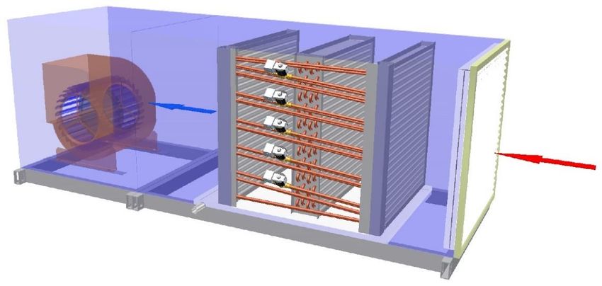
DEHUMIDIFIER HEAT PIPES IN AIR CONDITIONING
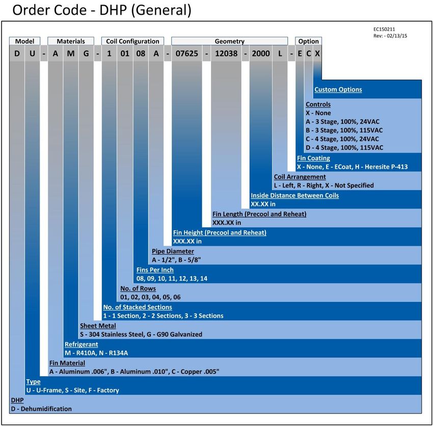
HPT dehumidifier Heat Pipes are usually installed in A/C units in a ”wrap-around” configuration.
The first Heat Pipe module precools the entering air before it goes through the cooling coil. The
precooled air then approaches the cooling coil at a lower temperature, allowing it to be overcooled
by the cooling coil before being reheated by the second Heat Pipe module. The function of the
Heat Pipe is performed passively without any mechanical moving parts. The Heat Pipe is activated
by the temperature difference between the air entering the precool Heat Pipe and the air leaving
the cooling coil.
Dehumidifier Heat Pipes can be installed around chilled water cooling coils as well as direct
expansion (DX) cooling coils.
Typical Installation of a Wrap-Around Heat Pipe in an Air
Handling Unit
Reheat Heat Pipe
Cooling Coil
Precool Heat Pipe
Extended Drain Pan
DHP™ Installation
DHP-2
2021-07-29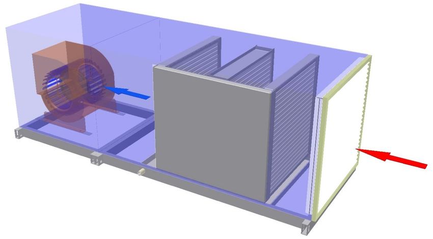
Methods of Installation

Factory Installed Wrap-Around Dehumidifier Heat Pipes DHP-F™

NEW: A/C units are shipped by the manufacturer/contractor to the HPT facility in Tampa, Florida
where they are factory retrofitted and then shipped to the final destination.

Site Installed Wrap-Around Dehumidifier Heat Pipes                  DHP-S™

Units are retrofitted on site by HPT Heat Pipe trained technicians. Air conditioning units are site
inspected with all measurements taken; Heat Pipes are then designed and built to fit. A site
installation crew from HPT is sent to install the Heat Pipes. Heat Pipes have been site installed by
this method in many locations inside the United States, including Hawaii, as well as the Caribbean,
Asia, and South America.

U-Frame Wrap-Around Dehumidifier Heat Pipes                       DHP-U™

U-Frame Heat Pipes are made-to-fit. They are designed for installation in an air handler or A/C
unit at an equipment manufacturer’s facility. These are ideal units for installation into custom or
configured air handlers.

Vertical Tubes Wrap-Around Dehumidifier Heat Pipes DHP-V™

Vertical Tubes Wrap-Around Dehumidifier Heat Pipes are made-to-fit units designed either for
site installation, installation at the HPT facility in Tampa, or at an OEM facility. These are ideal
units for medium to large air handlers with varying reheat requirement. For best results, the reheat
side of the system is elevated above the precool section.

                                                                                                  DHP-3
                                                                                              2021-07-29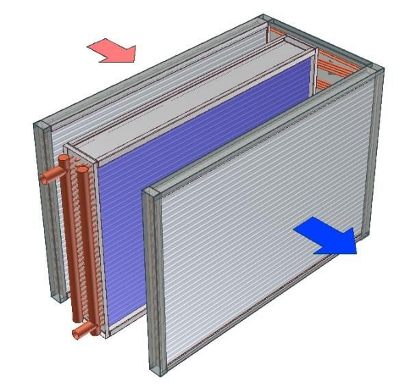
Installation Requirements

A typical two-row Heat Pipe installation system (2 rows precooling, 2 rows reheating) requires 4"
of space on both sides of the cooling coil. The Heat Pipes are typically mounted on both sides of
the cooling coil. If required, and where space is available, Heat Pipes can be mounted in access
sections provided by the manufacturer of the A/C unit or air hander.
One-row systems require approximately 2.25" minimum of space on both sides of the cooling coil.
Two-row systems require 3.25" on both sides. Three-row systems require 4.25" on both sides.
Four-row Heat Pipe systems require 5.5" on both sides of the cooling coil, and so on.
For OEM installation, HPT will ship DHP-U™ sections to the air hander manufacture. The AHU
needs to be designed to allow for the DHP-U™ retrofit . Besides needing to have space before
and after cooling to install the heat pipes’ precool section and reheat sections, room is also needed
at the back end of the cooling coil to allow for the encased connecting tubes. This space varies
depending on number of rows and if controllable or not. Refer to HPT online selection software
SelectPlus™ drawings for exact dimensions.
When considering fitting Heat Pipes into a unit, keep in mind the following:
1)     Site Installation
       Since Heat Pipe connecting tubes are always at the
       back end of the cooling coil (the end of the cooling
       coil that does not have manifolds, see diagram to
       the right), there must be room at that end for
       installation of connecting tubes, and also room
       between the A/C unit and the nearest object next to
       it to allow for technicians to work on the
       connecting tubes, evacuate, and charge. and for
       future maintenance on valves if the system is
       controllable.
2)     Factory Installation
                                                                         Cooling Coil with Heat Pipes
       As in site Installation, controllable Heat Pipes need
       extra room for wiring and solenoid valve servicing after the A/C unit is installed on-site. The non-
       controllable Heat Pipes have no moving parts on the connecting tubes end. Access room to that
       end is recommended but not critical.
3)     Airflow Direction
       Airflow direction is critical for heat pipe installation and must be indicated on units to be retrofitted
       at the factory. Heat Pipes will not work with a wrong airflow direction. This is even more critical for
       DHP-U™ since it is a finished unit and will be installed into AHU directly at a customer’s facility.
4)     Condensate Management
       Precool section of the DHP™ can and will condense moisture. Therefore provisions of moisture
       capture and drainage have to be taken into account for all DHP™ installations. It is also
       recommended that the reheat heat pipes section is installed over a drain pan for cleaning purposes.

                                                                                                             DHP-4
                                                                                                         2021-07-29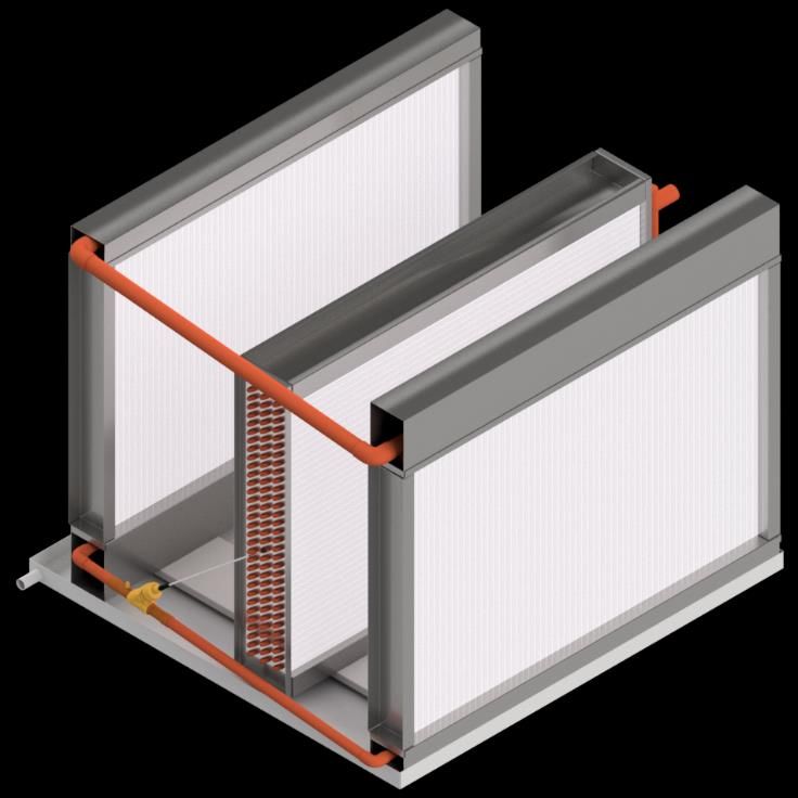
Types of Units That Can Be Fitted with Heat Pipes

Wrap-around dehumidifier Heat Pipes can be installed in almost any air handler or A/C unit. HPT
has extensive Heat Pipe installation experience with equipment manufactured by Carrier, Lennox,
Daikin, Trane, JCI, Addison, TMI, Air Enterprises, Seasons-4, Haakon, Annexair, Venmar and
many others. If in doubt, check with your local HPT representative or with the HPT’s main office
for installation requirements in specific units.

Below is a sample of units that can be fitted with wraparounds.

                                                                                              DHP-5
                                                                                          2021-07-29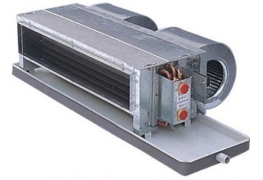
Types of Units That Can Be Fitted with Heat Pipes (continued)

                                                                    DHP-6
                                                                2021-07-29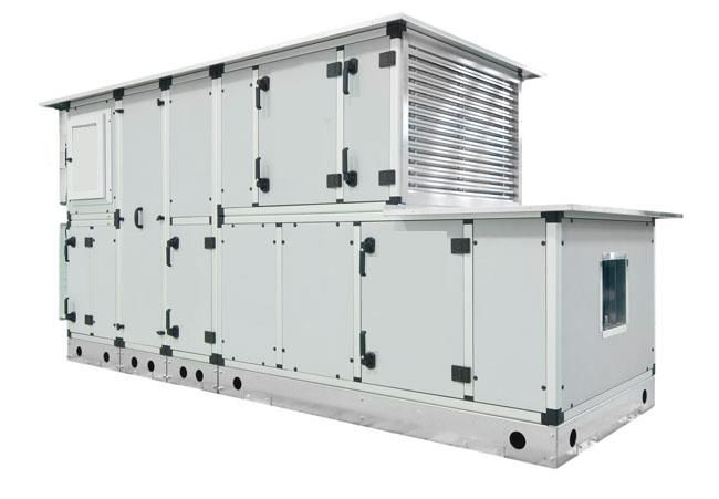
Dehumidifier Heat Pipes

Features and Benefits

Design Features

•   Totally Passive
    The standard dehumidifier Heat Pipes are totally passive with no moving parts.
•   Versatile
    Dehumidifier Heat Pipes can be designed to fit almost any size air handler. The amount of
    precool and reheat can be adjusted by correctly selecting the number of tube rows and the fin
    density. Dehumidifier Heat Pipes can be installed around cooling coils in air handlers, in
    DX, split, and packaged air conditioning units.
•   Low Maintenance
    Since Heat Pipes have no moving parts and are activated only by the difference in
    temperature between the air entering the precool Heat Pipe and the air leaving the cooling
    coil, they need very little attention. Only periodic cleaning is required.
•   Durability
    Since Heat Pipes are sensible energy transfer devices, Dehumidifier Heat Pipes stay dry most
    of the time. All HPT Heat Pipes are made of high quality copper tubes, and galvanic
    corrosion is not an issue in most applications. (For corrosive environments, coils coatings
    are available). Heat Pipes typically outlast the cooling coils of the air conditioning system
    in which they are installed.
•   Compact
    Since dehumidifier Heat Pipes wrap around the cooling coils, no additions to the air
    conditioning units are normally needed. Typically little room is needed inside A/C units to
    accommodate the Heat Pipes.
•   Controllability
    Controllability of Heat Pipes is offered as an option. This allows the operator to turn the
    Heat Pipes on-off or modulate their performance.
•   Quality
    With the Heat Pipe Technology name, you are guaranteed the best product. Product testing
    is part of our standard procedure to ensure top quality.

                                                                                               DHP-7
                                                                                           2021-07-29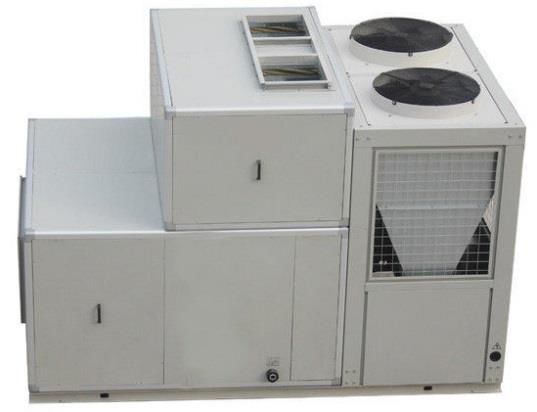
Benefits
•   Increase Moisture Removal of A/C Units
    The first module of the wrap-around Heat Pipe precools the entering air. This causes the
    approach temperature of the air to the cooling coil to be lower. If the cooling coil works at
    same capacity, the air leaves the cooling coil will be colder with a lower dew point and a
    lower absolute humidity ratio. That means more moisture will be removed from air.. Part
    of the cooling coil sensible capacity is converted into extra latent capacity. Because of this,
    a DX System, according to how it is controlled, may have a longer run time in order to satisfy
    the thermostat. Because of these two effects and depending on the design of the Heat Pipes,
    the cooling coil can extract over 30% to 100% more moisture than a cooling coil without
    Heat Pipes.
•   Dryer Supply Ducts
    After leaving the cooling coil, the air is reheated by the second Heat Pipe module. This
    lowers the relative humidity ratio of the supply air. In a typical system with 2 or 3 row
    DHP™, the relative humidity ratio is lowered from nearly 100% leaving the cooling coil to
    approximately 70% leaving the second Heat Pipe module. If the relative humidity ratio in
    occupied spaces and low velocity ducts and plenums exceeds 70%, fungal contamination
    (for example, mold, mildew, etc.) may occur. HPT Dehumidifier Heat Pipes help solve this
    problem.
•   Humidity Control
    Buildings in humid climates frequently encounter serious humidity problems that need to be
    addressed. Other buildings used for specific purposes like hospitals, certain food processing
    plants, and some manufacturing plants require humidity to be kept at a low level. HPT
    Dehumidifier Heat Pipes are usually the most efficient method of humidity control in these
    situations. By helping the A/C system remove more moisture from the air, the required
    humidity levels can be easily achieved.
•   Energy Savings through Passive Precooling and Reheat
    Since Heat Pipes provide reheat by utilizing the heat from the entering air, there is none or
    reduced requirement for active reheat?. The additional cooling needed to compensate for the
    reheat is also provided passively by the first Heat Pipe module as it extracts heat from the
    entering air. Using Heat Pipes to replace active reheat results in substantial savings. A
    payback of one year or less may be achieved when electric reheat is replaced with
    dehumidifier Heat Pipes.
•   Energy Savings with Higher Thermostat Setting
    As the relative humidity in a building is reduced by the addition of Heat Pipes, the thermostat
    can be set to a higher temperature while maintaining the same level of comfort and saving
    additional energy.
•   Equipment Savings through Downsizing
    To cope with high humidity loads, the most frequently used technique is to oversize the A/C
    unit and then reheat the overcooled air. This results in high operating costs as well as initial
    equipment cost. If dehumidifier Heat Pipes are used, oversizing and active reheating can be
    avoided. With a chilled water system, HPT Heat Pipes allow the designer not only to reduce
    the size of the cooling coil but also to reduce the chilled water requirement. Thus, a smaller
    chiller unit can be used.

                                                                                                  DHP-8
                                                                                              2021-07-29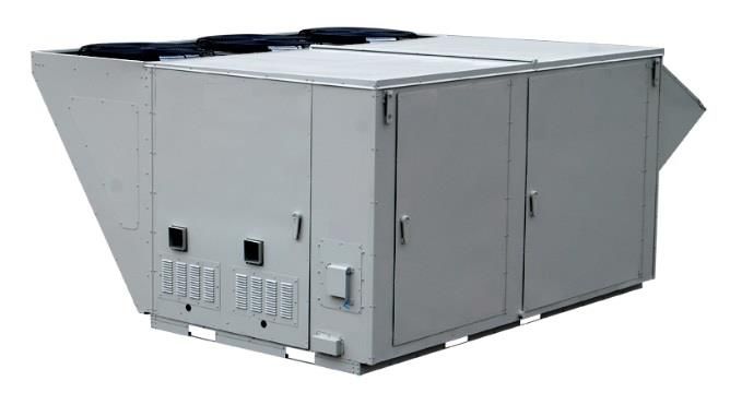
Products

DHP-F™: Factory Installed Wrap-Around Dehumidifier Heat Pipes

DHP-S™: Site Installed Wrap-Around Dehumidifier Heat Pipes

                     Wrap-Around Dehumidifier Heat Pipes installed in cooling coil section

Features
    Factory or site installed wrap-around Dehumidifier Heat Pipes are the most versatile
    Dehumidifier Heat Pipes. They can be installed around the cooling coil in most any air
    conditioning unit to remove more moisture and to provide the dehumidifying benefits of
    overcooling and reheat with no overcooling or reheat cost. Highly experienced HPT
    technicians install the Heat Pipes at both the HPT factory and on site assuring excellent
    installation and proper operation.
Applications
    Typically installed in A/C manufacturers’ catalog units: Chilled water air handlers and direct
    expansion (DX) equipment, both packaged and split systems.

                                                                                                 DHP-9
                                                                                             2021-07-29
DHP-U™: U-Frame Dehumidifier Heat Pipes
Features
These units are completely fabricated at the HPT factory and can be installed around a
cooling coil without assistance by HPT technicians. They can be slid into place horizontally
or dropped into place from above.
Applications
Typically installed by custom air conditioning unit manufacturers around chilled water or
DX cooling coils.
DHP-10
2021-07-29Controllable Dehumidifier Heat Pipe Systems
DHP-FC™: Factory Installed Controllable Dehumidifier Heat Pipes
DHP-SC™: Site Installed Controllable Dehumidifier Heat Pipes
DHP-UC™: U-Frame Controllable Dehumidifier Heat Pipes
DHP-V™: Vertical Tube Wrap-Around Dehumidifier Heat Pipes
Features
Wrap-around heat pipes are normally installed as passive devices designed to match the
requirements of their installation. Sometimes the need for maximum sensible cooling
overrides the need for humidity control. Because of this, it is necessary to temporarily lower
or shut off the reheat action of the heat pipe.
However, when reheat is shut off, the precool also shuts off, increasing the load on the
cooling coil. Unless the cooling coil has extra capacity, the cooling coil leaving air
temperature and dewpoint will be higher than with the heat pipe operating. There will still
be more sensible cooling available than with the heat pipe operating, just not as much as it
would first appear. For example, many cooling coils have a 55° F saturated leaving air
temperature. With a typical two row wrap-around heat pipe, the reheat is about 10° F,
warming the air to 65° F. Shutting off the reheat and the precool means a cooling coil with
a fixed capacity, or one already operating at maximum capacity, may only be able to cool
the air to a dew point between 58° F and 62° F. The need for the heat pipe performance to
be less than the maximum but more than zero brings about the need for controllable heat
pipes.
Applications
Typically used for applications where there is limited cooling capacity or where
dehumidification needs to be closely controlled, or variable reheat requirement.
Following are the two main applications for controlling Dehumidifier Heat Pipes:
1. Electrically Operated Solenoid Valves, DHP-FC™, DHP-SC™, DHP-UC™
For remote control of an operating heat pipe, normally open (NO) electric solenoid valves can be
installed in the liquid return lines of the individual heat pipe circuits. The number of valves needed
is determined by the size of the heat pipe, the number of rows, and the degree of control desired.
It may not be necessary to install controls on all circuits if partial control is sufficient. The total
heat pipe system can have a mix of controlled and uncontrolled circuits for systems that do not
require shutting off 100% of the heat pipe operation.
As the heat pipe size and/or number of rows increase, the number of valves increases. When the
installation calls for approximately 15 or more solenoids, the 30 Watts of electrical power needed
DHP-11
2021-07-29to operate each also becomes an important consideration. In this case consideration should be
given to 115 VAC solenoids to avoid the added cost of having to install large power transformers,
or to consider a different control option.
Total No. % Heat Pipe Effect
of Stages
3 0, 33, 66, 100
4 0, 25, 50, 75, 100
Valve Control Examples
Solenoid Valve Controlled Heat Pipe System
Heat pipes with control solenoids can be installed in factory fitted wrap-around heat pipes and in
U-framed heat pipes. The size of the solenoids adds considerable depth to the heat pipe connection
section (F dimension). The cooling coil may need to be ordered shorter than normal, or the AHU
section ordered wider than normal, in order to accommodate the solenoids. In some cases, where
this is not possible, an outside enclosure is built to house the connecting section of the heat pipes.
In addition, this area must have access after the AHU is installed. One row of solenoids (for a one
or two rows heat pipes) needs a connection section depth of 5 inches; two rows of solenoids (for a
three or four rows heat pipes) need a depth of 9 inches. These dimensions are illustrated below.
F
Rows E F F
n Rows E
W/O W/
Valves
Valves
Cooling Coil
1 2.25 1.50 5.00 (Not Included)
2 3.25 2.00 5.00
3 4.25 2.75 9.00 n Rows E
4 5.50 3.25 9.00
5 6.75 4.00 13.00 Dimensions for wrap-around heat pipes with solenoid
6 8.00 4.50 13.00 valves
The circuiting required for installing solenoids lends itself to building the heat pipe with multiples
of two rows only. A three row controllable requires the same number of solenoids as a four row
controllable.
DHP-12
2021-07-292. Vertical Tube Wrap-Around Dehumidifier Heat Pipes, DHP-V™
The manifolded heat pipe allows
controllability by using a different heat pipe
construction method. The heat pipe coils are
built with vertical tubes manifold together at
the top and at the bottom, creating a vapor line
at the top and a liquid line at the bottom.
There are only two lines per circuit crossing
over between the two heat pipe sections,
although they are quite a bit larger than the
normal ½ inch crossover tubes used in regular
heat pipe systems. The vapor line is typically
1.625 or 2.125 inches OD while the liquid line
is typically 1.375 inches OD. By installing a
proportional control electronic refrigeration
valve in the liquid line, the liquid return can
be controlled thus controlling the heat pipe
performance. These heat pipes can be installed Schematic of a Vertical Tube Controllable
DHP-V™, Heat Pipe and Cooling Coil
in multiple banks high.
An electric step motor valve is typically used to provide modulating control. The valves are
controlled from a separate HPT furnished control box including microprocessor(s), with signals
originating from the Building Automation System, which provides the sensors and is programmed
to operate the heat pipe system to control the supply leaving air temperature as required.
This design only uses electric power when the valve setting is changing. The top and bottom
manifolds do reduce the available finned area, making this design most suitable for large
installations. In units up to about 30 inches of finned height, solenoid valves should be considered;
for larger units, manifolded heat pipes should be considered. There are also other considerations.
This product is not available for selection in our online software SelectPlus™. Please contact HPT
for advice.
DHP-13
2021-07-29.
DHP-14
2021-07-29Dehumidifier Heat Pipes
ENGINEERING SPECIFICATIONS
Factory Installed Wrap-Around Dehumidifier Heat Pipes DHP Series
1. GENERAL
❑ Air Handler(s) ❑ Packaged Air Conditioning Equipment shall be equipped with
❑ Standard
❑ Tilted Enhanced
Dehumidifier Heat Pipes supplied by Heat Pipe Technology, Inc. to precool the return/outside air
and reheat the supply air in a wrap-around configuration. The precool Heat Pipe module shall be
located immediately before the cooling coil and the reheat module of the Heat Pipe shall be located
immediately after the cooling coil. Heat Pipe circuits comprise multiple tubes connected in series,
end-to-end to form a closed, continuous loop. Both vapor and liquid will travel in the same
direction around the circuit in a single convectional path, making wicking and capillary action
unnecessary for continuous heat transfer. Both Heat Pipe modules shall be inside the equipment
cabinet. The interconnecting piping between the Heat Pipe modules shall be located within the
assembled access/coil/access sections. If not, the piping shall be external, but enclosed within a
removable, insulated enclosure supplied and installed by others. When possible, all
interconnecting piping shall be located at the end of the cooling coil opposite from the coil header
and piping connections. Any deviation from the specifications must be approved by the engineer
no less than ten days prior to the project bid date. No consideration of alternates will be given
after that time. Heat pipes shall be completely manufactured and fully assembled at the
manufacturer’s facility or on site by factory personnel. Conversion of third party coils is not
acceptable.
2. CONFIGURATION IN MODULAR AIR HANDLERS
The precool Heat Pipe module shall be located immediately upstream of the cooling coil section
and the reheat Heat Pipe module shall be located immediately downstream of the cooling coil
section with drain pans, or a single extended drain pan, positioned beneath. ❑ For optimal
accessibility between the cooling coil and the Heat Pipe modules, the air handler cooling coil
section(s) shall be supplied with two (2) factory installed blank sections located immediately
before and after the cooling coil section. Each section shall be provided with an integral
condensate drain pan and drain pan condensate connection of the same construction as specified
for the cooling coil. The precool Heat Pipe module shall be located within the provided blank
section before the cooling coil section, and the reheat Heat Pipe module shall be located within the
provided blank section after the cooling coil section.
DHP-15
2021-07-293. OPTIONAL CONTROL VALVE FEATURE
All or a portion [SPECIFY] of the Dehumidifier Heat Pipe circuits shall be equipped with solenoid
operated control valves to control the operation of the Heat Pipe circuits. The electrical power
required by the solenoid valves shall be: ❑ 24 VAC ❑ 120 VAC. The solenoid valves shall be
wired to a terminal block within a NEMA enclosure located on the: ❑ exterior surface of the
equipment cabinet or ❑ interior as indicated.
The Building Automation System shall provide the sensors necessary for determination of heat
pipe staged operation and the BAS computer shall be programmed to send the operating control
signals to the solenoid valves as required for correct system operation. The control signal shall go
through a BAS interface installed near the heat pipe NEMA box. All additional wiring, relays,
transformers, power supply etc. necessary to interface with the equipment control system, shall be
provided and installed by others. Closing of a valve shall inactivate the Heat Pipe circuit in which
it is installed. The valves shall be normally open. The control valves shall be grouped such that
each group of valves shall control a designated fraction of the Heat Pipe circuits. With all control
valves open, the Dehumidifier Heat Pipe assembly will operate at full capacity. If all the circuits
are equipped with control valves, then closing all the valves will stop all Heat Pipe operation.
Manufacturer shall provide at least three (3) references for successful controllable wraparound
heat pipe installations in operation for at least three (3) years.
4. HEAT PIPES
1) The Heat Pipe supplier shall have a minimum of 5 years of experience designing and
installing Heat Pipes specifically for dehumidification applications.
2) The tubes shall be 1/2” OD copper, of specific design for Heat Pipe application,
permanently expanded onto the fin collar to form a firm, rigid, and complete pressure
contact at all operating conditions. Aluminum tubes will not be allowed.
3) The fin surface shall be continuous plate type ❑ aluminum ❑ copper fins of specific
design to produce maximum heat transfer efficiency for Heat Pipe applications. Airside
pressure loss shall be as given on the schedule, or otherwise specified. Fin density and the
number of rows of tubes shall be as specified.
4) ❑ The Heat Pipe modules shall have an optional protective coating of ❑ E-Coat, similar
to Electrofin or ❑ phenolic, similar to Heresite. Heat pipes shall be dipped and completely
submerged to insure full coverage of coating - spray coatings are not acceptable.
5) Heat transfer fluid shall be classified as Safety Group A1 in ASHRAE Standard 34-2013.
6) Heat Pipe capacities, entering and leaving dry and wet bulb temperatures, and face velocity
shall be as specified.
7) The Heat Pipes shall be installed as shown on the submittal drawings.
8) Frames, mounting structure, and drain pan extensions (if required) shall be minimum 16
gauge ❑ galvanized steel ❑ stainless steel.
DHP-16
2021-07-299) Heat Pipe interconnecting piping and circuitry shall be as specified by Heat Pipe
Technology design. Each circuit shall be individually processed, charged, hermetically
sealed, and tested.
10) Scheduled effectiveness or heat recovery shall be met at a minimum and total pressure drop
shall not be exceeded. The resulting Recovery Efficiency Ratio, or RER, shall therefore
be met at a minimum.
11) The Heat Pipes shall be ETL listed to UL standard 207 and CSA C22.2.140.3.
12) The Heat Pipe heat exchanger shall have a five (5) year limited warranty. All components
such as valves and dampers shall carry a 12 month warranty.
U-Frame Dehumidifier Heat Pipes (Installed by Other OEMs)
1. GENERAL
❑ Air Handler(s) shall be equipped with
❑ Standard
❑ Tilted Enhanced
Dehumidifier Heat Pipes supplied by Heat Pipe Technology, Inc. to precool the return/outside air
and reheat the supply air in a wrap-around configuration. The Dehumidifier Heat Pipes shall be
pre-fabricated in a U-Frame arrangement comprised of precool Heat Pipe and reheat Heat Pipe
heat exchangers together in one assembly such that the assembly may be inserted into an air
conditioning unit with the legs of the U-Frame unit on either side of the cooling coil of the air
conditioning unit. The U-Frame assembly shall be configured such that the precool Heat Pipe
shall be located immediately before the cooling coil and the reheat Heat Pipe shall be located
immediately after the cooling coil. Heat Pipe circuits comprise multiple tubes connected in series,
end-to-end to form a closed, continuous loop. Both vapor and liquid will travel in the same
direction around the circuit in a single convectional path, making wicking and capillary action
unnecessary for continuous heat transfer. The interconnecting piping between the Heat Pipe
modules shall be located within the U-Frame unit. Any deviation from the specifications must be
approved by the engineer no less than 10 days prior to the project bid date. No consideration of
alternates will be given after that time. Heat pipes shall be completely manufactured and fully
assembled at the manufacturer’s facility or on site by factory personnel. Conversion of third party
coils is not acceptable.
2. OPTIONAL CONTROL VALVE FEATURE
All or a portion [SPECIFY] of the Dehumidifier Heat Pipe circuits shall be equipped with solenoid
operated control valves to control the operation of the Heat Pipe circuits. The electrical power
required by the solenoid valves shall be: ❑ 24 VAC ❑ 120 VAC. The solenoid valves shall be
wired to a terminal block within a NEMA enclosure located on the exterior surface of the
equipment cabinet. All additional wiring, relays, transformers, and power supply etc. necessary
DHP-17
2021-07-29to interface with the equipment control system, shall be provided and installed by others. Closing
of a valve shall inactivate the Heat Pipe circuit in which it is installed. The valves shall be normally
open. The control valves shall be grouped such that each group of valves shall control a designated
fraction of the Heat Pipe circuits. With all control valves open, the Dehumidifier Heat Pipe
assembly will operate at full capacity. If all the circuits are equipped with control valves, then
closing all the valves will stop all Heat Pipe operation. Manufacturer shall provide at least three
(3) references for successful controllable wraparound heat pipe installations for at least three (3)
years.
3. HEAT PIPES
1) The Heat Pipe supplier shall have a minimum of 5 years of experience designing and
installing Heat Pipes specifically for dehumidification applications.
2) The tubes shall be ½” OD copper, of specific design for Heat Pipe application, permanently
expanded onto the fin collar to form a firm, rigid, and complete pressure contact at all
operating conditions. Aluminum tubes will not be allowed.
3) The fin surface shall be continuous plate type ❑ aluminum ❑ copper fins of specific
design to produce maximum heat transfer efficiency for Heat Pipe applications. Airside
pressure loss shall be as given on the schedule, or otherwise specified. Fin density and the
number of rows of tubes shall be as specified.
4) ❑ The Heat Pipe modules shall have an optional protective coating of ❑ E-Coat, similar
to Electrofin or ❑ phenolic, similar to Heresite. Coils shall be dipped and completely
submerged to insure full coverage of coating - spray coatings are not acceptable.
5) Heat transfer fluid shall be classified as Safety Group A1 in ASHRAE Standard 34-2013.
6) Heat Pipe capacities, entering and leaving dry and wet bulb temperatures, and face velocity
shall be as specified.
7) The frame shall be minimum 16 gauge ❑ galvanized steel ❑ stainless steel.
8) Heat Pipe interconnecting piping and circuitry shall be as specified by Heat Pipe
Technology design. Each circuit shall be individually processed, charged, hermetically
sealed, and tested. Interconnecting piping shall be fully enclosed to provide complete
protection.
9) Scheduled effectiveness or heat recovery shall be met at a minimum and total pressure drop
shall not be exceeded. The resulting Recovery Efficiency Ratio, or RER, shall therefore
be met at a minimum.
10) The Heat Pipes shall be ETL listed to UL standard 207 and CSA C22.2.140.3.
11) The Heat Pipe heat exchanger shall have a five (5) year limited warranty. All components
such as valves and dampers shall carry a 12 month warranty.
DHP-18
2021-07-29Factory or Site Installed Wrap Around Dehumidifier Heat Pipes DHP-V Series
1. GENERAL
Air handlers shall be equipped with Dehumidifier Heat Pipes supplied by Heat Pipe
Technology, to precool the return/outside air and reheat the supply air in a wrap-around
configuration. Heat Pipe system shall be comprised of one, two, three, four or more circuits.
Both Heat Pipe modules shall be located inside the equipment cabinet. The interconnecting
piping- supplied and installed by others- between the Heat Pipe modules shall be located
❑ within the air handler, or ❑ external, but enclosed within a removable, insulated
enclosure supplied and installed by others. All interconnecting piping shall be located at
the back end of the cooling coil (not the headers end). Any deviation from the
specifications must be approved by the engineer no less than ten days prior to the project
bid date. No consideration of alternates will be given after that time. Heat pipes modules
shall be designed, manufactured and assembled at the manufacturer’s facility by factory
personnel. Conversion of third party coils is not acceptable.
2. CONSTRUCTION
❑ Heat Pipe coil tubes shall be oriented vertical and the fins run horizontal. Each two
rows shall be manifolded together into one liquid line at the bottom and one vapor line at
the top and constitute one circuit. Combining headers of multiple circuits into one common
vapor header and one common liquid header will reduce performance and is not
permissible. Each heat pipe section shall be installed level end to end. Reheat section shall
be installed with an elevational offset relative to the precool section, as specified by HPT,
in order to enhance performance.
❑ Extended drain pans (provided by others) to be installed under and downstream of the
precool section, or ❑ A moisture eliminator shall be installed immediately downstream of
the precool section of the heat pipe to capture condensate that may spit from the heat pipe
fins. Condensate shall drain out of the bottom into a drain pan (supplied by others). The
moisture eliminator shall be capable of capturing at least 99.75% of condensate when the
coil is producing condensate at a rate of 0 to 15 lbs. water/sqft/hour and coil airflow is ≤
700 SFPM. Static pressure loss shall not exceed 0.18 in.wg. at 500 SFPM.
The moisture eliminator blades will be constructed of ABS plastic and meet UL Standard
94 classification V-0, which requires blades to self-extinguish within 10 seconds. It will
incorporate an additive that protects against fungal and bacterial deterioration to provide
long-term protection against fungal and bacterial attack and help prevent surface growth,
permanent staining, embrittlement and premature product failure. The anti-fungal and anti-
bacterial additive shall be mixed with the polymer and shall not be a coating, which could
wear off over time.
3. CONFIGURATION IN MODULAR AIR HANDLERS
DHP-19
2021-07-29The precool Heat Pipe module shall be located immediately upstream of the cooling coil
section and the reheat Heat Pipe module shall be located immediately downstream of the
cooling coil section. For optimal accessibility between the cooling coil and the Heat
Pipe modules, the air handler shall be supplied with two (2) factory installed blank sections
located immediately before and after the cooling coil section. Each section shall be
provided with an integral condensate drain pan and drain pan condensate connection of the
same construction as for the cooling coil. The precool Heat Pipe module shall be located
within the provided blank section before the cooling coil section, and the reheat Heat Pipe
module shall be located within the provided blank section after the cooling coil section.
4. OPTIONAL CONTROL VALVE FEATURE
All or a portion [SPECIFY] of the Heat Pipe circuits shall be equipped with modulating
control valves to control the operation of the Heat Pipe circuits. Each circuit shall have
one modulating step motor valve in the lower liquid line in an accessible location. Each
valve will connect to a printed circuit board in a NEMA 12 enclosure that contains the
number of control boards to control all valves in the system and the appropriate power
conversion. The customer supplied electrical power to the control panel power supply
transformer shall be: ❑ 120 VAC ❑ 208 VAC ❑ 230 VAC 1 phase 60 Hz. The NEMA
box shall be located on the ❑ exterior or ❑ interior surface of the equipment cabinet as
indicated ❑ or on a nearby surface.
The Building Automation System (BAS) shall provide the sensors necessary for
determination of heat pipe modulation operation and the BAS computer shall be
programmed to send the operating control signals to the modulating valves’ control boards
as required for correct system operation. The control signal shall go through a BAS
interface installed near the heat pipe NEMA box. The BAS control signal provided shall
be ❑ 0 to 10 volt DC or ❑ 4-20 mA.
All additional wiring shall be provided and installed by others. With all control valves
open, the wrap around heat pipe assembly will operate at full capacity. Modulating one
valve closed restricts the liquid return flow and reduces the heat transferred by the heat
pipe until closing the valve shuts off that circuit.
5. HEAT PIPES
1) The Heat Pipe supplier shall have a minimum of 5 years of experience designing and
installing Heat Pipes specifically for dehumidification applications.
2) The tubes shall be 1/2” OD copper, of specific design for Heat Pipe application,
permanently expanded onto the fin collar to form a firm, rigid, and complete pressure
contact at all operating conditions. Aluminum tubes will not be allowed.
3) The fin surface shall be continuous plate type ❑ aluminum ❑ copper fins of specific
design to produce maximum heat transfer efficiency for Heat Pipe applications. Airside
pressure loss shall be as given on the schedule, or otherwise specified. Fin density and the
number of rows of tubes shall be as specified.
DHP-20
2021-07-294) ❑ The Heat Pipe modules shall have an optional protective coating of ❑ E-Coat, similar
to Electrofin or ❑ phenolic, similar to Heresite. Heat pipes shall be dipped and completely
submerged to insure full coverage of coating - spray coatings are not acceptable.
5) Heat transfer fluid shall be classified as Safety Group A1 in ASHRAE Standard 34-2013.
6) Heat Pipe capacities, entering and leaving dry and wet bulb temperatures, and face velocity
shall be as specified.
7) The Heat Pipes shall be installed as shown on the submittal drawings.
8) Frames, mounting structure, and drain pan extensions (if required) shall be minimum 16
gauge ❑ galvanized steel ❑ stainless steel.
9) Heat Pipe interconnecting piping and circuitry shall be as specified by Heat Pipe
Technology design. Each circuit shall be, pressure tested, vacuumed, charged, and sealed.
10) Scheduled effectiveness or heat recovery shall be met at a minimum and total pressure drop
shall not be exceeded. The resulting Recovery Efficiency Ratio, or RER, shall therefore
be met at a minimum.
11) The Heat Pipes shall be ETL listed to UL standard 207 and CSA C22.2.140.3.
12) The Heat Pipe heat exchanger shall have a five (5) year limited warranty. All components
such as valves and dampers shall carry a 12 month warranty.
DHP-21
2021-07-29Installation List
Recent Domestic Installations
Wrap-Around Dehumidifier Heat Pipes (DHP™)
State City Location
Alabama Haynesville Central Elementary
Arkansas Searcy John Soules Foods
Little Rock Blue Cross Blue Shield South Building
California Los Angeles Ronald Reagan UCLA Medical Center
Connecticut Hartford Connecticut Historical Society
Putnam Putnam High School
New Haven Helene Grant School
Delaware Dover Allen Frear Elementary School
Florida Pensacola Naval Air Station
Citrus Springs Citrus Springs Middle School
Ocala Life Care Center
Pompano Beach Unipharma LLC
Orlando Walt Disney World Animal Kingdom Lodge
Clearwater Morton Plant Hospital
W. Palm Beach West Palm Beach VA
Marco Island Marriott
Biscayne Florida International University
Orlando Walt Disney Work Kadini Village
Mary Esther Hurlburt AFB
Gainesville University of Florida - Fine Arts
Miami Wyndam Hotel
Tampa St. Joseph's Hospital
Tampa University of South Florida
Georgia Columbus Ft. Benning McBride Elementary
Kennesaw KSU Sturgis Library
Ringgold & Lavonia Welcome Center
Atlanta Federal Reserve Kitchen
Tattnall & Hawkinsville Lockheed Martin Space Fence
Atlanta Westminster School – Carlyle Fraser Library
Cumming Forsyth County Public Library
Hawaii Honolulu Kawananakoa Middle School
Hilo University of Hawaii Hilo Life Science
Honolulu Ala Moana Hotel
Kaneohe P-864 MALS 24 Aircraft Maintenance Facility
Illinois Chicago Nordstrom Tower
Chicago Mariano’s New City Lincoln Park
Indiana Clinton Eli Lilly C92
Bloomington Indiana University Musical Arts Center
DHP-22
2021-07-29Iowa Iowa City University of Iowa Pool
Louisiana New Orleans New Orleans Airport
Iberville Parish Math, Science, and Arts (MSA) Academy
Galliano South Lafourche High School
Houma Terrabonne Criminal Complex
New Orleans Villa St. Maurice
Lafayette Parish Lafayette Parish School Board Career Center
Maryland Parkville Oak Crest Village Senior Living
Stevensville Stevensville Middle School
Bowie Bowie State University Center
Massachusetts Cambridge Massachusetts Institute of Technology Grad Student Dorm
Wellesley Benchmark Senior Living
Mississippi Jackson University of Mississippi Medical Center
Gulfport Naval Construction Battalion Center, Bldg. 418
Meridian Naval Air Station
New Jersey Parsippany AKF Biomet 3
New York New York Memorial Sloan Kettering Cancer Center Lab 64
Saratoga Springs Saratoga Hospital
New York Extell
Staten Island Curtis High School
North Carolina Greenville East Carolina University Student Union
High Point High Point University
North Dakota Wahpeton Wahpeton High School
Ohio Cincinnati GE Aviation
University Heights Cleveland Heights - University Heights High School
Unilever Cincinnati
Pennsylvania Nazareth Martin Guitar
Philadelphia Children’s Hospital of Philadelphia
Bryn Mawr Bryn Mawr College - Haffner Dormitory
Puerto Rico San Juan University of Puerto Rico – Institute of Neurobiology
Guayama Pfizer
South Carolina Charleston Boeing B860
Clemson Clemson University – Barnet Hall
Tennessee Memphis University of Memphis
Texas Austin The Independent
Austin Texas Facilities Commission – WPC Bldg. 8
San Antonio Alamo Stadium
Plano Granite Park Hilton Hotel
Wisconsin Milwaukee Milwaukee Center for Independence
DHP-23
2021-07-29Recent International Installations
Dehumidifier Heat Pipes (DHP™)
Country State/Province City Location
Canada Ontario Guelph University of Guelph
Ontario Ottawa Canadian Science & Technology Museum
Ontario Thornhill Atlas Global Healthcare
Univ. of Toronto – Center for Engineering,
Ontario Toronto Innovation, & Entrepreneurship
Ontario Niagara Falls Niagara Region Police Station
Ontario Kitchner Royal Bank of Canada
Ontario Ottawa 180 Wellington Building (Historic)
Ontario Toronto Ryerson Biomedical Research Lab
Quebec Laval Sanofi Canada
Ontario Brampton Peel Memorial Hospital
Ontario Toronto 100 Adelaide
Ontario Ottawa 100 Maple Grove Road
Ontario Borden Canadian Forces Military Police Academy
Colombia Antioquia Medellin Museum of Modern Art
India Hyderabad Prayagh Nutri Products
Chennai Hospital
Korea Gyeonggi-do Siheung-Si Daeduck Electronics Co., Ltd.
Jongno-gu Seoul Seoul University Hospital
Electronics & Telecommunications Research
Yuseong-ro Daejeon Institute - R&D Center
Panama Panama Rio Nato Playa Blanca Town Center
Philippines Philippines Manila Manila Bay Resort
Singapore Singapore Regent Hotel
Singapore Nanyang Technical Univ. – Lecture Theatre
Singapore Hotel @ Victoria Street
Thailand Prachuabkhirikhan Hua Hin Intercontinental Hotel
CPF Animal Lab
Phuket Phuket International Hospital
Rayong PTT Maintenance & Engineering Co. Ltd.
Chanburi Thai Oil Public Company – Lab
Bangkok Bangkok Hospital
UAE Abu Dhabi Warner Brothers Theme Park
Dubai City Mall
Abu Dhabi Abu Dhabi University (College of Engineering)
Abu Dhabi Capital Mall
Dubai W Hotel
Dubai Dubai Port World
Dubai Stanford University
Dubai Nova Hospital
Dubai Audi Services Center
Dubai Grand Millennium Hotel
DHP-24
2021-07-29Dubai McDonald's @ Me’aisem City Centre
Qatar Doha Samrya Quartier Hotel
Doha Supreme Command Building
Doha Wakra Clinic
Doha Ministry of Finance, Phase II
Doha Aspire Academy
Doha MKM Towers
Oman Muscat Oman Convention & Exhibition Center
Muscat Royal Oman Police Officers Club
Muscat Special Task Force Complex at Nizwa
Muscat Park Inn Hotel
Muscat Fitout of Carrefour
DHP-25
2021-07-29Dehumidifier Heat Pipes
Heat Pipes Selection Procedure
The Heat Pipe cloud-based Software, SelectPlus™, developed and copyrighted by HPT is designed for
selecting and sizing HPT’s Dehumidifier Heat Pipes. Please logon to www.heatpipeselect.com to get your
user name and password for full accessibility.
DHP-26
2021-07-29Dehumidifier Heat Pipes
Five-Year Limited Warranty
Subject to the following conditions, Heat Pipe Technology, Inc. (HPT), warrants this product to be free from defects
in material and workmanship for a period of FIVE YEARS for the heat exchangers only from the date of installation, but
not to exceed 90 days from the date of shipment. Control valve(s) and control box carry a 12 month warranty. This
warranty is in lieu of all other warrants not expressly set forth herein, whether expressed or implied by operation of law
or otherwise. In the event this product fails under normal use and service within the applicable period, HPT will correct,
repair or, at its sole discretion, replace the defective product or refund the purchase price of products which are returned
freight prepaid to HPT for inspection, when accompanied by proof of purchase and written claims of defect, and which
upon inspection by HPT, do comply with the terms of this warranty.
This warranty applies to the first retail buyer and extends to any subsequent owners of the systems.
The cost of replacement parts or components shall be determined by the price schedule in effect at the time of
submission of warranty claim.
Repair or replacement parts will be furnished F.O.B. factory in all cases.
If HPT elects to replace or provide a refund, the defective product must be returned to HPT free and clear of liens or
other encumbrances.
Limitations on Liability
This warranty does not cover and no warranty is made with respect to:
A. Failures not reported to HPT within the period specified above;
B. Failures or damage due to misapplication, misuse, abuse, improper storage or handling, abnormal conditions of
temperature, water, dirt, corrosive substances or other contaminants;
C. Products which have been repaired with parts or materials not furnished or approved by HPT or by its authorized
dealers or representatives, or products which have been in any way tampered with or altered;
D. Products damaged in shipment or storage or otherwise without fault of HPT;
E. Normal maintenance as outlined in the installation and servicing instructions or owner’s manual including coil
cleaning, filter cleaning and periodic flushing of systems;
F. Damage or repairs required as a consequence of faulty installation or application by others;
G. Damage or repairs required as a consequence of any misapplication, abuse, improper servicing, unauthorized
alteration or improper operation;
H. Damage as a result of floods, winds, fires, lightning, accidents, corrosive atmosphere or other conditions beyond
the control of HPT;
I. Damage resulting from freezing of domestic water or condensate, inadequate or interrupted water supply, use of
corrosive water, fouling or restriction of the water circuit by foreign material or like causes;
J. Damage resulting from operation with an inadequate supply of air or water;
K. Dampers or other mechanical options.
HPT total responsibility for any claims, damages, losses or liabilities related to the product covered hereunder shall not
exceed the purchase price of such product. In no event shall HPT be liable for any special, indirect, incidental or
consequential damages of any character, including but not limited to loss of use of productive facilities or equipment,
lost profits, property damage, transportation, installation or removal, lost production, or personal injury whether suffered
by Purchaser or any third party. HPT disclaims all liability for any and all costs, claims, demands, charges, expenses
or other damages, either direct or indirect, incident to personal injury or property damage arising out of any cause of
action based on strict liability.
Some states do not allow the exclusion or limitation of incidental or consequential damages or limitations on how long
an implied warranty lasts, so the exclusion or limitation above of consequential damages or the limitation of time above
on implied warranties may not apply to you.
This warranty gives you specific legal rights and you may have other rights, which may vary from state to state.
DHP-27
2021-07-29Dehumidifier Heat Pipes
Warranty Registration
To ensure your warranty protection, please fill in the Warranty Registration Form and mail or e-mail it to:
Heat Pipe Technology, Inc.
6904 Parke East Blvd.
Tampa, FL 33610
info@heatpipe.com
Phone: (813) 470-4250
WARRANTY REGISTRATION FORM
Customer Name:
Customer Address:
Phone: ( ) - Fax: ( ) -
Please check one: Owner Dealer
Serial No: Model No:
Type of Product:
Date of Installation: Dealer/Installer:
Name & Address of Dealer/Company You Purchased from
Name:
Address:
Customer Signature:
DHP-28
2021-07-29You can also read