Simulation of the clinical procedure by digital intraoral palpation of the greatest prominence of the Infrazygomatic crest for mini-implants insertion
←
→
Page content transcription
If your browser does not render page correctly, please read the page content below
Research, Society and Development, v. 11, n. 5, e54211528496, 2022
          (CC BY 4.0) | ISSN 2525-3409 | DOI: http://dx.doi.org/10.33448/rsd-v11i5.28496

Simulation of the clinical procedure by digital intraoral palpation of the greatest
prominence of the Infrazygomatic crest for mini-implants insertion
Simulação do procedimento clínico por palpação digital intraoral da maior proeminência da crista
Infrazigomática para inserção de mini-implantes
Simulación del procedimiento clínico por palpación digital intraoral de la mayor prominencia de la
cresta Infracigomática para inserción de mini-implantes

                                                   Received: 03/25/2022 | Reviewed: 04/03/2022 | Accept: 04/11/2022 | Published: 04/15/2022

                                                                                                                 Oscar Mario Antelo
                                                                                            ORCID: https://orcid.org/0000-0001-8944-5329
                                                                                          Pontifícia Universidade Católica do Paraná, Brazil
                                                                                                       E-mail: oarortodoncia@hotmail.com
                                                                                                               Armando Yukio Saga
                                                                                            ORCID: https://orcid.org/0000-0002-4585-6588
                                                                                          Pontifícia Universidade Católica do Paraná, Brazil
                                                                                                         E-mail: saga.armando@gmail.com
                                                                                                                 Ariel Adriano Reyes
                                                                                             ORCID: https://orcid.org/0000-0003-0699-8759
                                                                      Pontificia Universidad Católica Madre y Maestra, Dominican Republic
                                                                                                           E-mail: drarielreyes@gmail.com
                                                                                                              Thiago Martins Meira
                                                                                            ORCID: https://orcid.org/0000-0003-3862-5797
                                                                                                 Universidade do Estado da Bahia, Brazil
                                                                                                      E-mail: thiagomartinsm@gmail.com
                                                                                                          Sérgio Aparecido Ignácio
                                                                                            ORCID: https://orcid.org/0000-0002-8242-3781
                                                                                          Pontifícia Universidade Católica do Paraná, Brazil
                                                                                                                E-mail: s.ignacio@pucpr.br
                                                                                                         Orlando Motohiro Tanaka
                                                                                            ORCID: https://orcid.org/0000-0002-1052-7872
                                                                                          Pontifícia Universidade Católica do Paraná, Brazil
                                                                                                              E-mail: tanakaom@gmail.com

      Abstract
      The objective of this cross-sectional retrospective study was to simulate using cone-beam computed tomography
      (CBCT) in adults, the clinical procedure performed by intraoral digital palpation of the greatest prominence (GP) of the
      Infrazygomatic crest (IZC) for mini-implants (MIs) insertion. CBCT images of 34 adults (14 men, 20 women), aged
      18.0 to 57.7 years (mean, 32.2 years) were selected. On 3D reconstruction, the GP of the IZC region was determined
      using the anatomical morphology, and its anteroposterior position on the selected axial slice was evaluated relative to
      the dental reference located between the maxillary first and second molars (U6–U7). On the selected coronal slice, two
      reference lines were established to evaluate the insertion angle and insertion depth (IZC thickness) for MIs. The same
      procedure was performed on slices with intervals of 1 mm mesially as well as distally up to reach 4 mm. The right and
      left sides were measured. In relation to U6-U7, the GP of the IZC was 0.19 mm (±1.79) mesial on the right side and
      0.29 mm (±1.65) mesial on the left side. The greatest bone thickness of the IZC was 4.95 mm (±2.39) on the right side,
      3.81 mm distal from U6-U7, and 4.79 mm (±2.13) on the left side, 3.71 mm distal from U6-U7. The GP-IZC determined
      visually on the 3D reconstruction, did not present the greatest bone thickness. The bone tended to gradually become
      thicker distal to the GP-IZC and the dental reference U6-U7.
      Keywords: Infrazygomatic crest; Mini-implants; Skeletal anchorage.

      Resumo
      O objetivo deste estudo transversal retrospectivo foi simular, por meio de tomografia computadorizada de feixe cônico
      (TCFC) em adultos, o procedimento clínico realizado por palpação digital intraoral da maior proeminência (MP) da
      crista Infrazigomática (CIZ) para inserção de mini-implantes (MIs). Foram selecionadas imagens de TCFC de 34 adultos
      (14 homens, 20 mulheres), com idades entre 18,0 e 57,7 anos (média de 32,2 anos). Na reconstrução 3D, a MP da região
      da CIZ foi determinada pela morfologia anatômica, e sua posição anteroposterior no corte axial selecionado foi avaliada
      em relação à referência dentária localizada entre os primeiros e segundos molares superiores (U6–U7). No corte coronal

                                                             1
Research, Society and Development, v. 11, n. 5, e54211528496, 2022
                (CC BY 4.0) | ISSN 2525-3409 | DOI: http://dx.doi.org/10.33448/rsd-v11i5.28496

         selecionado, duas linhas de referência foram estabelecidas para avaliar o ângulo de inserção e a profundidade de inserção
         (espessura da CIZ) para MIs. O mesmo procedimento foi realizado em cortes com intervalos de 1 mm mesial e
         distalmente até atingir 4 mm. Os lados direito e esquerdo foram medidos usando os mesmos procedimentos. Em relação
         a U6-U7, a MP da região CIZ foi 0,19 mm (±1,79) mesial do lado direito e 0,29 mm (±1,65) mesial do lado esquerdo.
         A maior espessura óssea do CIZ foi de 4,95 mm (±2,39) no lado direito, 3,81 mm distal de U6-U7 e 4,79 mm (±2,13)
         no lado esquerdo, 3,71 mm distal de U6-U7. A MP-CIZ determinado visualmente na reconstrução 3D, não apresentou
         a maior espessura óssea. O osso tendeu a tornar-se, gradualmente, mais espesso distalmente ao MP-CIZ e à referência
         odontológica U6-U7.
         Palavras-chave: Crista Infrazigomática; Mini-implantes; Ancoragem esquelética.

         Resumen
         El objetivo de este estudio retrospectivo transversal fue simular mediante tomografía computarizada de haz cónico
         (TCHC) en adultos, el procedimiento clínico realizado por palpación digital intraoral de la mayor prominencia (MP) de
         la cresta Infracigomática (CIC) para la inserción de mini-implantes (MIs). Se seleccionaron imágenes CBCT de 34
         adultos (14 hombres, 20 mujeres), de 18,0 a 57,7 años (media, 32,2 años). En la reconstrucción 3D, se determinó la MP
         de la CIC utilizando la morfología anatómica, y se evaluó su posición anteroposterior en el corte axial seleccionado en
         relación con la referencia dental ubicada entre los primeros y segundos molares maxilares (U6-U7). En el corte coronal
         seleccionado, se establecieron dos líneas de referencia para evaluar el ángulo de inserción y la profundidad de inserción
         (espesura CIC) para MIs. El mismo procedimiento se realizó en cortes con intervalos de 1 mm tanto mesialmente como
         distalmente hasta llegar a 4 mm. Los lados derecho e izquierdo se midieron utilizando los mismos procedimientos. En
         relación a U6-U7, la MP de la CIC fue de 0,19 mm (±1,79) mesial del lado derecho y 0,29 mm (±1,65) mesial del lado
         izquierdo. El mayor grosor óseo de la CIC fue de 4,95 mm (±2,39) del lado derecho, 3,81 mm distal de U6-U7, y de
         4,79 mm (±2,13) del lado izquierdo, 3,71 mm distal de U6-U7. La MP-CIC determinada visualmente sobre la
         reconstrucción 3D, no presentó la mayor espesura ósea. El hueso tendía a volverse gradualmente más espeso distal a la
         MP-CIC y la referencia dental U6-U7.
         Palabras clave: Cresta Infracigomática; Mini-implantes; Anclaje esquelético.

1. Introduction
         Patients often reject extractions in orthodontic treatment and demand for alternative treatment to avoid them. (Keles &
Sayinsu, 2000) Alternatively, perform distalization of maxillary molars is relatively difficult compared with other types of tooth
movements. (Liou et al., 2004) Successful complete maxillary dentition distalization depends on consistent temporary skeletal
anchorage with MIs, placed distant from the roots. (Ali et al., 2016; Lima Jr et al., 2022; Wu et al., 2011)
         The IZC is one of the anatomical sites distant from roots, which allows unobstructed tooth movement during complete
distalization of the maxillary dentition, decreasing the chance of root contact and damage. (Uribe et al., 2015; Vargas et al.,
2020) The IZC is a pillar of cortical bone located in the lower part of the zygomatic process of the maxilla, intraorally, it is a
bony protuberance palpable along the curvature between the alveolar process and the zygomatic process of the maxilla. (Liou et
al., 2007) Anatomically, the IZC has two cortical plates: the buccal cortical plate and the cortical plate of the maxillary sinus
floor. This anatomical advantage allows bicortical fixation, which contributes in improving the primary stability of the MI. (Jia
et al., 2018)
         According to Liou et al (Liou et al., 2007) and Baumgaertel et al (Baumgaertel & Hans, 2009) the IZC is located on the
buccal surface of the zygomatic process of the maxilla, above the first permanent molars. According to De Clerck et al (De
Clerck et al., 2002) and Chang et al (Chang et al., 2019) the IZC, located between the first and second molars, is the chosen site
for placing MIs at a safe distance from the roots of maxillary molars.
         Some studies have evaluated the IZC in terms of bone thickness, MI insertion angle and height using CBCT.
(Baumgaertel & Hans, 2009; Lee et al., 2013; Liou et al., 2007; Murugesan & Sivakumar, 2020; Santos et al., 2017)
         Due to the growing demand of adult patients seeking conservative orthodontic treatment avoiding extractions, and the
frequent use of MIs as temporary skeletal anchorage, sometimes the clinician is based solely on his/her knowledge and clinical
experience to insert MIs in the IZC region without CBCT of the area. For this reason, the aim of this study was to simulate using
CBCT, the clinical maneuver, where the operator decides the insertion site of the MI by intraoral palpation of the greatest

                                                                2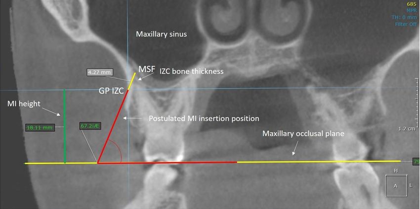
Research, Society and Development, v. 11, n. 5, e54211528496, 2022
             (CC BY 4.0) | ISSN 2525-3409 | DOI: http://dx.doi.org/10.33448/rsd-v11i5.28496

prominence of the IZC in Adults.

2. Methodology
Ethical considerations
         This cross-sectional study was approved by the Institutional Committee of Ethics with the register number 3.005.777.
The CBCT images of 34 adults (14 men, 20 women), aged 18.0 to 57.7 years (mean age, 32.2 years) of mestizo ethnicity were
selected from the database of a private tomographic laboratory in Santo Domingo, Dominican Republic, to assess the IZC crest
region, according to the objectives mentioned. The CBCT images were acquired using a Promax 3D Max (Plan-meca Inc,
Roselle, IL) device with an acquisition protocol of 90 kVp, 8–14 mA, 0.2mm-thick slices, 0.2-mm voxel size, and 20 × 20 cm
field of view. The inclusion criteria were CBCT images of adult patients over 18.0 years old, no craniofacial anomalies, trauma
or asymmetries, presence of complete maxillary and mandibular dentition with the exception of the third molars, no radiographic
signs of bone resorption or periapical problems, and good image quality. All CBCT images that do not comply with the
aforementioned inclusion criteria were excluded from this study.

Measurement protocol
         Initially, each CBCT image was adjusted in order to set the head position, considering the sagittal slice perpendicular
to the Frankfurt plane, the axial slice perpendicular to the midpalatal suture and the coronal slice perpendicular to the maxillary
occlusal plane (plane formed between the distobuccal cusps of both maxillary first molars). All adjustments and measurements
were performed using On Demand 3D software (On Demand 3D software version 1, Cyber Med, Seoul, South Korea) (Figure
1).

               Figure 1. Tomographic adjustment: A, coronal slice; B, axial slice; C, sagital slice; D, 3D
               reconstruction.

                                                         Source: Authors.

                                                                3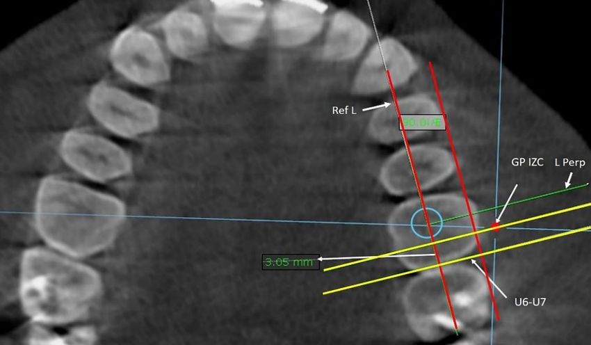
Research, Society and Development, v. 11, n. 5, e54211528496, 2022
             (CC BY 4.0) | ISSN 2525-3409 | DOI: http://dx.doi.org/10.33448/rsd-v11i5.28496

         First, in the 3D reconstruction, the greatest prominence of the IZC region (GP-IZC) was determined in the frontal view
and corroborated with the lateral view to determine the insertion site of the MI (Figure 2).

                  Figure 2. Determination of the greatest prominence of the Infrazygomatic crest region (red
                  point) in 3D reconstruction for selection of the mini-implant insertion site: A, Frontal view;
                  B, Lateral view.

                                                         Source: Authors.

         The GP-IZC is comparatively the site chosen by digital palpation for MI insertion, when the clinician seeks for a site of
greater prominence in the IZC region. Immediately, on the selected axial slice was evaluated its anteroposterior position relative
to the dental reference located at the contact point of the crowns of the maxillary first and second molars (U6-U7) on each side.
A reference line (Ref. L.) tangent to the vestibular surface of the premolars and molars was established. This line was moved to
the center of the occlusal aspects of the crowns, and another line perpendicular (L. Perp.) to this reference line was constructed
(Figure 3). Posteriorly, two lines parallel (yellow) to the L. Perp. were established, one passing through the selected GP-IZC
(selected site for the MI insertion) and the other through the dental reference U6-U7. The distance between both lines provided
the anteroposterior position of the greatest prominence of the IZC relative to the dental reference U6-U7 (Figure 3).

                    Figure 3. Evaluation of the anteroposterior position of the greatest prominence of the
                    Infrazygomatic crest (mini-implant insertion site selected) relative to the dental
                    reference located at the contact point of the crowns of U6-U7 on each side in the
                    selected axial slice.

                                                         Source: Authors.

                                                                4
Research, Society and Development, v. 11, n. 5, e54211528496, 2022
(CC BY 4.0) | ISSN 2525-3409 | DOI: http://dx.doi.org/10.33448/rsd-v11i5.28496
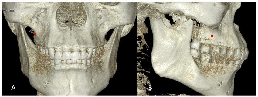
Second, on the selected coronal slice, two reference lines were established to evaluate the insertion angulation of the
MI. The first reference line was the maxillary occlusal plane, a plane formed between the distobuccal cusps of both maxillary
first molars. The second reference line was the postulated mini-implant insertion position, a line formed between the selected
insertion site of the MI on the buccal cortical bone of the GP-IZC, until it made contact with the cortical bone of the maxillary
sinus floor (MSF). The insertion angle of the MI was measured between the intersection of the postulated MI insertion position
line and the maxillary occlusal plane. The IZC thickness was measured from GP-IZC to MSF. The same procedure was
performed on slices at intervals of 1 mm for mesial and distal up to reach 4 mm, maintaining the same initial MI insertion height
(Figure 4).
Figure 4. Coronal slice, reference lines constructed to measure the Infrazygomatic crest thickness
and the mini-implant insertion angle and height.
Source: Authors.
Third, on the selected coronal slice, the height of the MI insertion point (greatest prominence of the IZC) was measured
from the distobuccal cusp of the maxillary first molar to the GP-IZC.
All measurements were performed on the right and left sides.
Statistical analysis
A previously trained and calibrated investigator (O.M.A.R) performed all measurements on CBCTs under identical
conditions. To test the reliability of the measurements, 30 CBCTs were randomly selected for re-measurement by simple random
sampling 2 weeks after the initial measurement. The Dahlberg’s error test was used to verify the reliability of the two-time
measurements. All data collected were tabulated in an electronic database and later subjected to specific statistical analyses using
the SPSS statistical program (version 25.0; IBM, Chicago, IL, USA).
Descriptive statistics were performed to identify the general and specific characteristics of the study sample. The
normality assumptions were verified using the Kolmogorov-Smirnov test.
The paired Student’s t-test was used to compare the measurements between the two sides and on the same side.
Comparisons of measurements between sexes were performed using the Mann-Whitney U test. The level of significance used
was P ˂ 0.05.
5Research, Society and Development, v. 11, n. 5, e54211528496, 2022
(CC BY 4.0) | ISSN 2525-3409 | DOI: http://dx.doi.org/10.33448/rsd-v11i5.28496
3. Results
The Dahlberg’s error test showed satisfactory reliability of the two-time measurements (< 20% error). The mean
mesiodistal position of the GP-IZC was located 0.19 mm (±1.79) mesial to U6-U7 on the right side and 0.29 mm (±1.65) mesial
to U6-U7 on the left side (Table 1).
The mean value of the greatest bone thickness of the IZC was 4.95 mm (±2.39) on the right side and 4.79 mm (±2.13)
on the left side (Tables 2 and 3). There were no statistically significant differences when comparing the mean bone thickness
values of the IZC region between genders.
The mean MI height above the maxillary occlusal plane was located 17.92 mm (± 2.23) on the right side and 17.58 mm (± 2.37)
on the left side.
Table 1. Descriptive statistics of the mesiodistal position of the greatest
prominence of the IZC assessed on both sides.
95% Confidence interval
Standard
Minimum Maximum Lower limit Upper limit
Mean Deviation
Right side (mm) 0.19 1.79 -2.74 3.84 -0.43 0.81
Left side (mm) 0.29 1.66 -2.89 3.07 -0.28 0.86
Source: Authors.
Table 2. Descriptive statistics of IZC thickness evaluated in the coronal slice on the right
side.
95% Confidence interval
Standard
Mean Minimum Maximum Lower limit Upper limit
Deviation
4mm mesial 4.16 2.46 1.66 14.73 3.30 5.02
3mm mesial 4.09 2.42 1.69 13.90 3.25 4.94
2mm mesial 4.12 2.38 1.82 13.21 3.28 4.95
1mm mesial 4.13 2.32 1.72 12.24 3.31 4.94
Initial point 4.19 2.29 1.85 11,58 3.39 4.99
1mm distal 4.31 2.26 2.06 10.84 3.52 5.10
2mm distal 4.47 2.29 2.18 10.47 3.67 5.27
3mm distal 4.65 2.27 2.25 10.47 3.86 5.44
4mm distal 4.95 2.39 2.32 11.49 4.11 5.78
Source: Authors.
6Research, Society and Development, v. 11, n. 5, e54211528496, 2022
(CC BY 4.0) | ISSN 2525-3409 | DOI: http://dx.doi.org/10.33448/rsd-v11i5.28496
Table 3. Descriptive statistics of IZC thickness evaluated in the coronal slice on the
left side
95% Confidence
Standard Lower Upper
Mean Deviation Minimum Maximum limit limit
4mm mesial 4.60 2.51 1.73 13.24 3.73 5.48
3mm mesial 4.38 2.46 1.80 12.60 3.52 5.25
2mm mesial 4.32 2.34 1.75 11.64 3.50 5.14
1mm mesial 4.17 2.27 1.66 11.09 3.38 4.97
Initial point 4.11 2.13 1.67 10.61 3.36 4.85
1mm distal 4.17 2.09 1.57 11.03 3.44 4.90
2mm distal 4.27 2.04 1.84 11.35 3.56 4.98
3mm distal 4.53 2.04 1.93 11.72 3.82 5.25
4mm distal 4.79 2.13 2.08 12.25 4.05 5.54
Source: Authors.
Statistically significant differences found on comparing the mean bone thickness values between each slice studied on
the same side are shown in Table 4 for the right side and in Table 5 for the left side. The bone tended to gradually become thicker
distally in relation to the dental reference U6-U7 and the GP-IZC.
Table 4. Comparing the mean bone thickness between each slice on the right side.
4mm 3mm 2mm 1mm Initial 1mm 2mm 3mm 4mm
mesial mesial mesial mesial point distal distal distal distal
4mm mesial 0.018
3mm mesial 0.037 0.005
2mm mesial 0.024 0.003
1mm mesial 0.016 0.002
Initial point 0.048 0.012 0.001
1mm distal 0.006 0.000
2mm distal 0.008 0.000
3mm distal 0.001
Source: Authors.
Table 5. Comparing the mean bone thickness between each slice studied on the left side
4mm 3mm 2mm 1mm Initial 1mm 2mm 3mm 4mm
mesial mesial mesial mesial point distal distal distal distal
4mm mesial
3mm mesial 0.001
2mm mesial 0.029
1mm mesial 0.014 0.032 0.031
Initial point 0.030 0.012 0.002
1mm distal 0.031 0.000
2mm distal 0.000 0.000
3mm distal 0.000
4mm distal
Source: Authors.
7Research, Society and Development, v. 11, n. 5, e54211528496, 2022
(CC BY 4.0) | ISSN 2525-3409 | DOI: http://dx.doi.org/10.33448/rsd-v11i5.28496
Table 6. Paired samples test results comparing MI insertion angle between both sides.
Right side Standard deviation Left side Standard deviation p value
Initial point 62.74 5.28 63.90 4.96 0.123
1 mm mesial 63.08 5.43 65.18 5.32 0.004
2 mm mesial 63.02 5.19 65.47 5.34 0.001
3 mm mesial 63.85 4.77 65.57 4.67 0.011
4 mm mesil 63.96 4.63 66.22 4.53 0.007
1 mm distal 63.40 5.34 64.96 5.86 0.013
2 mm distal 62.98 6.36 64.74 5.78 0.019
3 mm distal 62.75 6.15 65.03 4.79 0.014
4 mm distal 63.71 5.48 65.19 5.47 0.069
Source: Authors.
Comparing the right and left sides according to MI insertion angulation at each slice studied, statistically significant
differences were found in most slices, except at point 0 (P = 0.123) and point 4 mm distally (P = 0.069) (Table 6). The mean
value for MI insertion angulation on the right side was 63.28° and 65.14° on the left side.
There were no statistically significant differences when comparing the mean bone thickness values of the IZC region
between the right and left sides (P >0.05).
Between sexes, there were no statistically significant differences when comparing the mean bone thickness values in
the 9 coronal slices studied in the IZC region (P >0.05).
4. Discussion
Sometimes the clinician is based solely on his/her ability and clinical experience to insert MIs in the IZC region without
CBCT of the area. For this reason, the clinical procedure performed by intraoral digital palpation of the GP-IZC for MI insertion
in adults was simulated using CBCT.
In the present study, the mean position of the greatest prominence of the IZC was found to be 0.19 mm (± 1.79) mesial
on the right side and 0.29 mm (± 1.65) mesial on the left side, relative to the dental reference U6-U7. This was determined
visually in the 3D reconstruction of each patient, representing the clinical procedure by digital palpation performed by the
clinician.
By the way, Liu et al (Liu et al., 2017) observed that the U6-U7 region is the most ideal safe zone for placing MIs
in the buccal alveolar bone in the IZC region for maxillary dentition distalization.
The mean greatest bone thickness of the IZC was 4.95 mm (± 2.39) on the right side and 4.79 mm (± 2.13) on the left
side, and it was located 3.81 mm distal to the dental reference U6-U7 on the right side and 3.71 mm distal on the left side. It was
17.92 mm (± 2.23) height above the maxillary occlusal plane on the right side and 17.58 mm (± 2.37) on the left side. The overall
mean bone thickness was 4.35 mm. In relation to the mean IZC greatest prominence found, the IZC greatest thickness was
located 4 mm distally on both sides. The bone tended to gradually become thicker distally in relation to the dental reference U6-
U7 and the GP-IZC.
Some studies have evaluated the IZC in terms of bone thickness, MI insertion angle, and height using CBCT. In 2007,
Liou et al (Liou et al., 2007) measured the thickness of the IZC above the mesiobuccal root of the maxillary first molars at
different angles and positions and recommended 6 mm as the minimal IZC thickness for sustaining an MI, inserting it 14 to 16
mm height at an angle of 55° to 70° to the maxillary occlusal plane. Baumgaertel et al (Baumgaertel & Hans, 2009) investigated
the thickness of the IZC at three sites above the maxillary first molar and found an average bone depth of 6.17 to 7.05 mm at the
8Research, Society and Development, v. 11, n. 5, e54211528496, 2022
(CC BY 4.0) | ISSN 2525-3409 | DOI: http://dx.doi.org/10.33448/rsd-v11i5.28496
lowest measurement level selected; thereafter, the values gradually decreased until reaching the most apical measurement of 2.97
to 3.6 mm. Placement at the first level would violate the minimal safety recommended distance for MIs insertion. In addition,
Santos et al (Santos et al., 2017) evaluated the IZC at two selected points above the distobuccal root of the maxillary first molars
and found an overall mean IZC thickness of 2.49 mm and 2.29 mm, respectively.
In the present study, the average bone thickness of IZC was lower than the values obtained by Liou and Baumgaertel.
(Baumgaertel & Hans, 2009; Liou et al., 2007) This was probably owing to the following circumstances. First, a certain safety
distance is required. Maino et al (Maino et al., 2005) recommended 0.5 mm as the minimal safety distance to any adjacent
anatomical structure, and Baumgaertel (Baumgaertel & Hans, 2009) also used 0.5 mm; nevertheless, Liou et al (Liou et al., 2004)
recommended 2 mm. In our study, 1.25 mm was the minimal safety distance used. Therefore, it was necessary to place the MIs
in a more apical position, which resulted in a concomitant reduction of the IZC bone thickness. Second, the amount of alveolar
process height and depth; the buccal bone available surrounding the posterior maxillary roots in several patients was very thin
to support an MI; therefore, it was necessary to insert the MIs in a more apical position, resulting in a reduction of the IZC
thickness. Third, maxillary sinus pneumatization size; roots of the maxillary posterior teeth frequently cause convolutions in the
floor of the sinus, resulting in a reduction of the IZC thickness. Fourth, root length and buccolingual inclination of the maxillary
first and second molars; the greater the root length and buccal root inclination, the lesser the thickness of the IZC.
In contrast, the values obtained by Santos et al (Santos et al., 2017) were significantly lower than those obtained in the
present study because the MI insertion site selected by them was even more apical. In summary, the more apical the selected MI
insertion site, the lesser the bone thickness.
As mentioned above, Liou (Liou et al., 2007) recommended 6 mm as the minimal IZC thickness for sustaining a MI,
nevertheless, Costa et al (Costa et al., 1998) and Miyawaki et al (Miyawaki et al., 2003) mentioned that the cortical bone quality
and quantity are the major factors associated with primary stability. Farnsworth et al (Farnsworth et al., 2011) reported that the
average cortical thickness of the IZC is only 1.44 to 1.58 mm. As generally accepted, cortical bone thickness of more than 1 mm
is required for good stability of orthodontic MI. The thickness of the buccal cortical bone was not directly evaluated in the present
study, but the total thickness of the IZC according to the MI insertion angle was measured from the buccal cortical bone to the
cortical bone of the MSF. In this way, the MI insertion reaches bicortical fixation, achieving adequate primary stability by
mechanical retention.
Among the risks mentioned during the insertion of MIs in the IZC is also the possibility of penetrating and damaging
the maxillary sinus. Jia et al (Jia et al., 2018) determined the incidence of IZC MIs penetration into the maxillary sinus in clinical
practice using CBCT. The overall success rate of MIs inserted in the IZC was 96.7%, and 78.3% penetrated into the maxillary
sinus. They concluded that the incidence of penetration of IZC MIs into the sinus may be high, and penetration through double
cortical bone plates with limitation of penetration depth within 1 mm is recommended. On the other hand, Chang et al (Chang et
al., 2022) evaluated the success rate of MIs placed in the Infrazygomatic crest in relation to maxillary sinus penetration. They
observed that 48% of MI penetrated the maxillary sinus with a mean penetration length of 3.23 mm, however they concluded
that maxillary sinus perforation has no significant effect on MI survival, and none patient reported any adverse signs or symptoms
of sinus perforation. In the present study, the importance of bicortical penetration of MIs in the IZC to obtain adequate primary
stability was considered.
Lee et al (Lee et al., 2013) found that the IZC was clinically thicker in males than in females. In contrast, Santos et al
(Santos et al., 2017) mentioned that no statistically significant differences were detected between gender. In the present study,
there were no statistically significant differences when comparing the mean bone thickness values of the IZC region between
sexes.
In concordance with Lee et al (Lee et al., 2013), we found no statistically significant differences when comparing the
9Research, Society and Development, v. 11, n. 5, e54211528496, 2022
(CC BY 4.0) | ISSN 2525-3409 | DOI: http://dx.doi.org/10.33448/rsd-v11i5.28496
mean bone thickness values of the IZC region between the right and left sides. Comparing the right and left sides according to
MI insertion angulation at each slice studied, differences were found in most slices, except at point 0 and point 4 mm distally.
The average insertion angle of MI on the left side was higher compared to the right side.
A limitation of this study was that individuals in the sample were from a specific country with possible ethnic skeletal
features; therefore, caution is recommended when extrapolating these results to other populations. Nevertheless, the results
presented can be used as clinical knowledge to guide procedures of MI insertion in the IZC region.
As a suggestion to conduct a future study, it is recommended to have a larger sample size to clarify the findings presented
in this research.
5. Conclusion
Sometimes the operator is based solely on his/her ability and clinical experience to insert MIs in the IZC without aid of
CBCT. For this reason, the clinical procedure performed by intraoral digital palpation of the GP-IZC for MI insertion in adults
was simulated using CBCT, to have predictable clinical reference in the insertion of MIs.
The GP-IZC determined visually on the 3D reconstruction, did not present the greatest bone thickness. The bone tended
to gradually become thicker distal to the GP-IZC (MI insertion site selected by the operator) and the dental reference U6-U7.
Acknowledgments
The authors thank Dr Alexis Ovalle and Eng Francisco Ovalle for the help in the acquisition of the CBCT images, and
Dr Caio Manfro Bianeck, radiologist imaginologist for the help in the CBCT measurements.
References
Ali, D., Mohammed, H., Koo, S.-H., Kang, K.-H., & Kim, S.-C. (2016). Three-dimensional evaluation of tooth movement in Class II malocclusions treated
without extraction by orthodontic mini-implant anchorage. Korean J Orthod, 46(5), 280-289. 10.4041/kjod.2016.46.5.280
Baumgaertel, S., & Hans, M. G. (2009). Assessment of infrazygomatic bone depth for mini‐screw insertion. Clin. Oral Implants Res, 20(6), 638-642.
10.1111/j.1600-0501.2008.01691.x
Chang, C. H., Lin, J.-H., & Roberts, W. E. (2022). Success of infrazygomatic crest bone screws: patient age, insertion angle, sinus penetration, and terminal
insertion torque. Am J Orthod Dentofacial Orthop. 10.1016/j.ajodo.2021.01.028
Chang, C. H., Lin, J. S., & Roberts, W. E. (2019). Failure rates for stainless steel versus titanium alloy infrazygomatic crest bone screws: A single-center,
randomized double-blind clinical trial. Angle Orthod, 89(1), 40-46. 10.2319/012518-70.1
Costa, A., Raffainl, M., & Melsen, B. (1998). Miniscrews as orthodontic anchorage: a preliminary report. Int J Adult Orthodon Orthognath Surg, 13(3), 201-
209.
De Clerck, H., Geerinckx, V., & Siciliano, S. (2002). The zygoma anchorage system. J Clin Orthod, 36(8), 455-459.
Farnsworth, D., Rossouw, P. E., Ceen, R. F., & Buschang, P. H. (2011). Cortical bone thickness at common miniscrew implant placement sites. Am J Orthod
Dentofacial Orthop, 139(4), 495-503. 10.1016/j.ajodo.2009.03.057
Jia, X., Chen, X., & Huang, X. (2018). Influence of orthodontic mini-implant penetration of the maxillary sinus in the infrazygomatic crest region. Am J Orthod
Dentofacial Orthop, 153(5), 656-661. 10.1016/j.ajodo.2017.08.021
Keles, A., & Sayinsu, K. (2000). A new approach in maxillary molar distalization: intraoral bodily molar distalizer. Am J Orthod Dentofacial Orthop, 117(1),
39-48. 10.1016/s0889-5406(00)70246-0
Lee, H.-S., Choi, H.-M., Choi, D.-S., Jang, I., & Cha, B.-K. (2013). Bone thickness of the infrazygomatic crest area in skeletal Class III growing patients: A
computed tomographic study. Imaging Sci Dent, 43(4), 261-266. 10.5624/isd.2013.43.4.261
Lima Jr, A., Domingos, R. G., Ribeiro, A. N. C., Neto, J. R., & de Paiva, J. B. (2022). Safe sites for orthodontic miniscrew insertion in the infrazygomatic crest
area in different facial types: A tomographic study. Am J Orthod Dentofacial Orthop, 161(1), 37-45. 10.1016/j.ajodo.2020.06.044
10Research, Society and Development, v. 11, n. 5, e54211528496, 2022
(CC BY 4.0) | ISSN 2525-3409 | DOI: http://dx.doi.org/10.33448/rsd-v11i5.28496
Liou, E. J., Chen, P.-H., Wang, Y.-C., & Lin, J. C.-Y. (2007). A computed tomographic image study on the thickness of the infrazygomatic crest of the maxilla
and its clinical implications for miniscrew insertion. Am J Orthod Dentofacial Orthop, 131(3), 352-356. 10.1016/j.ajodo.2005.04.044
Liou, E. J., Pai, B. C., & Lin, J. C. (2004). Do miniscrews remain stationary under orthodontic forces? Am J Orthod Dentofacial Orthop, 126(1), 42-47.
10.1016/j.ajodo.2003.06.018
Liu, H., Wu, X., Yang, L., & Ding, Y. (2017). Safe zones for miniscrews in maxillary dentition distalization assessed with cone-beam computed tomography.
Am J Orthod Dentofacial Orthop, 151(3), 500-506. 10.1016/j.ajodo.2016.07.021
Maino, B. G.,Bednar, J., Pagin, P., & Mura, P (2003). Miniscrew implants: the spider screw anchorage system. 37(2), J Clin Orthod, 90-97.
Miyawaki, S., Koyama, I., Inoue, M., Mishima, K., Sugahara, T., & Takano-Yamamoto, T. (2003). Factors associated with the stability of titanium screws placed
in the posterior region for orthodontic anchorage. Am J Orthod Dentofacial Orthop, 124(4), 373-378. 10.1016/s0889-5406(03)00565-1
Murugesan, A., & Sivakumar, A. (2020). Comparison of bone thickness in infrazygomatic crest area at various miniscrew insertion angles in Dravidian
population–A cone beam computed tomography study. Int Orthod, 18(1), 105-114. 10.1016/j.ortho.2019.12.001
Santos, A. R., Castellucci, M., Crusoé-Rebello, I. M., & Sobral, M. C. (2017). Assessing bone thickness in the infrazygomatic crest area aiming the orthodontic
miniplates positioning: a tomographic study. Dental Press Journal of Orthodontics, 22, 70-76.
Uribe, F., Mehr, R., Mathur, A., Janakiraman, N., & Allareddy, V. (2015). Failure rates of mini-implants placed in the infrazygomatic region. Prog Orthod,
16(1), 1-6. 10.1186/s40510-015-0100-2
Vargas, E. O. A., de Lima, R. L., & Nojima, L. I. (2020). Mandibular buccal shelf and infrazygomatic crest thicknesses in patients with different vertical facial
heights. Am J Orthod Dentofacial Orthop, 158(3), 349-356. 10.1016/j.ajodo.2019.08.016
Wu, J.-H., Lu, P.-C., Lee, K.-T., Du, J.-K., Wang, H.-C., & Chen, C.-M. (2011). Horizontal and vertical resistance strength of infrazygomatic mini-implants. Int
J Oral Maxillofac Surg, 40(5), 521-525. 10.1016/j.ijom.2011.01.002
11You can also read