SOUNDTRAP ST500 USER GUIDE - AUGUST 2018 - OCEAN INSTRUMENTS
←
→
Page content transcription
If your browser does not render page correctly, please read the page content below
SoundTrap ST500 User Guide
          August 2018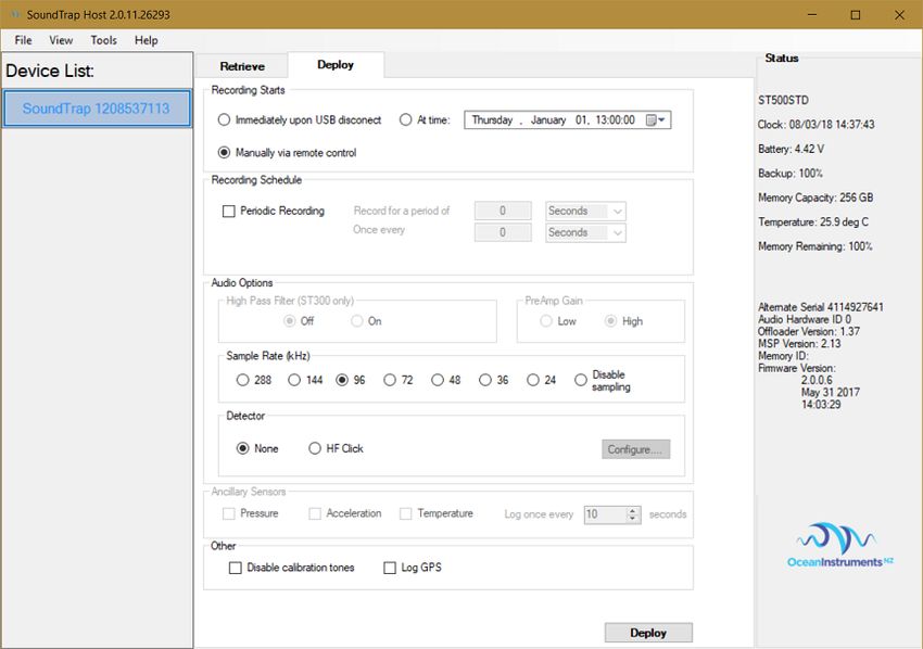
1   About this guide .............................................................................................................................. 4

2   Quick start guide ............................................................................................................................. 5

    2.1           Opening and closing the housing ..................................................................................... 5

    2.2           Batteries ........................................................................................................................... 5

    2.3           Installing the hydrophone ................................................................................................ 6

    2.4           Install the SoundTrap host on your PC............................................................................. 6

    2.5           Connect SoundTrap to your PC ........................................................................................ 7

    2.6           Check SoundTrap Status .................................................................................................. 8

    2.7           Configure the deployment ............................................................................................... 8

    2.8           Begin recording using the IR Remote Control ................................................................ 10

    2.9           Data Offload ................................................................................................................... 11

3   More details .................................................................................................................................. 12

    3.1           Adding additional memory cards ................................................................................... 12

    3.2           Data Files ........................................................................................................................ 13

    3.3           Calculation of deployment endurance ........................................................................... 14

    3.4           Deployment hardware ................................................................................................... 15

    3.5           Software updates ........................................................................................................... 16

    3.6           MSP firmware updates................................................................................................... 16

    3.7           Calibration ...................................................................................................................... 16

    3.8           Troubleshooting ............................................................................................................. 19

4   Appendices .................................................................................................................................... 20

    4.1           SoundTrap HF Click Detector (ST500HF Only)................................................................ 20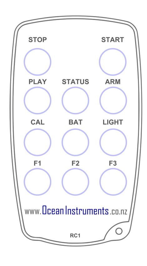
4.1.1   Click detector .......................................................................................................... 20

4.1.2   Snippet extractor .................................................................................................... 21

4.1.3   User parameters ..................................................................................................... 21

4.1.4   Output File formats ................................................................................................ 22

4.1.5   Click Detector Caveats and Cautions ...................................................................... 24
1 About this guide

This guide begins with a ‘Quick start’ section to help you get going with your new SoundTrap, including
software installation and basic deployment instructions. This is followed by several sections containing
more detailed information around operation, deployment, maintenance and troubleshooting. It is
highly recommended you read the entire guide to ensure you have a good understanding of the
instrument and how to get the most from its capabilities.
2 Quick start guide

2.1       Opening and closing the housing

Before opening the housing always check for flooding by shaking the recorder and listening for water
sloshing around inside. If flooding is suspected, then be aware that the housing may be pressurised
and therefore potentially dangerous. Carefully relieve any pressure by opening the small seal screw
at the base of the housing.

Opening the housing:

      •    Find the ‘open this end’ sticker on the housing.
      •    Screw open the endcap by turning counter clockwise
      •    You will probably need to insert a lever arm (eg screwdriver) in the provided holes to gain
           sufficient leverage.

Closing the housing:
      •    Carefully check the O’rings. Any nicks or scratches indicate they must be replaced.
      •    Lubricate O’rings with silicone grease.
      •    Check O’rings are properly seated and absolutely free of stray hair/grit etc
      •    Insert the chassis in the housing and screw all the way home, using a lever arm if necessary.
      •    Difficulty in screwing home the cap may indicate insufficient o’ring lubrication; do not apply
           excessive force – instead correct by applying o’ring lubricant.
      •    Replacement O’Rings should be type 83x3 N70 (Nitrile)

The O’ring checks are critically important to avoid damage. Any detritus or damage to the O’rings
may result in the housing being flooded which will almost certainly destroy the electronics.

2.2       Batteries
The SoundTrap ST500 is powered by up to 9 ‘D’ cell alkaline batteries. These are loaded in sets of 3,
meaning the recorder can be deployed with 3, 6 or 9 batteries depending on desired length of
deployment.
Note that advertised battery endurances are based on the commonly available Energizer brand
batteries, and performance of other brands is unknown.
Be careful to ensure correct battery polarity as indicated by the diagram in the battery
compartment. Once loaded, double check each battery’s polarity. Just one reversed battery is
enough to severely impact the overall battery life, and potentially cause damage through leaking
electrolyte. Always double check each cell’s polarity.
It is then very important that you verify the supply of power to the electronics. To do this press the
‘BAT’ button on the IR remote and observe the SoundTrap’s red status LED. If all is well you should
see two long red flashes. Note that there is a 10 second delay between connecting the batteries and
the software determining that the supply is stable. Observation of the two long flashes is
confirmation that the external battery is available, has viable batteries, and is ready to go.
A single short red flash indicates a problem. In this event, inspect the batteries for correct insertion
and adequate battery condition.
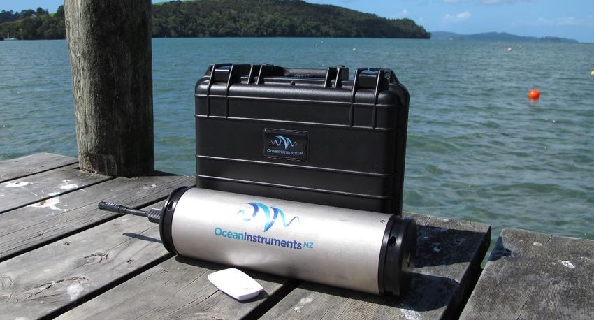
2.3 Installing the hydrophone
From the factory you’ll find the (removable) hydrophone stored inside the battery compartment for
shipping. Unpack and plug it into the wet socket in the recorder endcap, then secure with the locking
collar. The hydrophone is the most fragile component of the system, so best remove it during
transport, and take care to avoid impacts or crushing during deployment.
2.4 Install the SoundTrap host on your PC
To start using your SoundTrap you’ll need to install the SoundTrap Host software.
For correct operation of your ST500 it is critical to use SoundTrap Host version 3.3.1 or
later.
• Pre-installation Notes:
o The SoundTrap host software supports Windows 7,8 & 10 (32 or 64 bit versions).o Do not connect the SoundTrap to your computer until you have completed the
SoundTrap host software installation.
o The installation will be smoother if you’re logged into windows as an administrator.
• Visit www.OceanInstruments.co.nz/downloads/ to download the software.
• Download and run the installer.
• Once the install completes, run the SoundTrap Host application.
2.5 Connect SoundTrap to your PC
• Connect the SoundTrap using the USB cable provided.
• The drivers will take a couple of minutes to install. Once complete you should see your
SoundTrap appear in the ‘Device List’ on the left, as shown in figure 1.
• Select your SoundTrap by clicking its label on the left.
Figure 1 - The Device List2.6 Check SoundTrap Status
Note the ‘Status’ panel on the right (Figure 3). Verify that the memory is not full.
Figure 2 – Deploy Control
2.7 Configure the deployment
• Select the ‘Deploy’ tab as shown in figure 2.
• Configure the deployment parameters as follows:
o The ‘Recording Starts’ section determines when recording will begin. Recording can
begin immediately on disconnection of the USB cable, at a pre-determined date and
time, or manually using the IR remote control. Note that the remote can always be
used to override the other options.
o The ‘Recording Schedule’ section provides selection of continuous or periodic
recording. For continuous recording simply leave the ‘Periodic Recording’ option
unchecked.o Options available in the ‘Audio Options’ will vary according to your device’s
capabilities. Options include the following:
▪ Channel Selection selects which channels to record on.
▪ Sample Rate should be set based on the frequency band of interest and
data rate considerations. A 96 kHz sampling rate is often a good choice for
general environmental noise measurements. Contact OI support if unsure.
o Detector – see HF Click Detector section below.
• Once you’ve made your selections click the deploy button which will save the settings and
you’re ready to go. If you change your mind about something, just re-select the instrument
from the ‘Device List’.2.8 Begin recording using the IR Remote Control
You may use the remote control to start recording. The
recorder housing must be open to receive the signal from the
remote.
• Press ‘START’ to start recording.
• Press ‘STOP’ to stop recording.
• If you have set a recording to start recording at a
later time, the recorder will blink red to indicate it
is ‘armed’ and waiting.
• The ‘armed’ state is cancelled by pressing Stop key.
• Re-enable the armed state by pressing the ARM
button.
• You can verify recording has started by checking for slow blinking of the status (green)
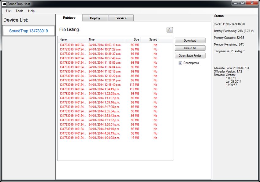
indicator.2.9 Data Offload
Once you’re done recording, reconnect your SoundTrap to your PC and select the Retrieve Tab, as
shown in figure 4.
Figure 3 – Retrieve Tab
• You will see a list of files in the SoundTrap’s memory, including the file name (made from the
device serial number plus local date and time), date recorded, approximate size and whether
it has yet been downloaded to your computer’s hard drive.
• Download individual files by right clicking the file and selecting ‘download’.
• By default, all files will be downloaded to a ‘SoundTrap’ folder under My Documents. This
default location can be changed under the ‘Tools’ menu.
• Click the ‘Open Save Folder’ button to open the download folder location.
• To download all files, select all files using the shift key, then click the ‘Download’ button.
• To delete, click the ‘Delete All’ button. Files cannot be deleted individually.• For faster download in the field, or to save disk space, un-check the ‘Decompress’ checkbox.
This will disable the decompression step of the offload process, meaning you will end up
with ‘sud‘ files only. These can be decompressed into wav files at a later time using the ‘File
Extraction’ option under the tools menu.
3 More details
3.1 Adding additional memory cards
The SoundTrap ST500 series have the capacity to add additional data storage in the form of 3
microSD card slots. Two reasons to consider using these are:
1. To lengthen deployment endurance by adding more memory. When using a high sample
rate, the internal memory may get exhausted before the batteries are depleted. Adding
memory cards may extend the recording duration by up to four times.
2. To enable quick field servicing. The internal memory is non-removable, meaning the data
must be downloaded by USB which can take several hours. Using memory cards enables fast
retrieval of data ie a fast re-deploy can be achieved by simply swapping out the memory
cards and batteries.
Important things to note before using this feature:
1. You should only use the recommended memory cards – Samsung Evo MicroSD. Counterfeits
of these cards are common, so only source from reputable suppliers. Using other card types
or counterfeits may result in performance issues such as greatly increased power
consumption, sampling gaps and unreliable recording.
2. The cards are used in the sequence 3->2->1->0 where 0 is the internal memory and 3 is the
bottom-most external card. Any full or missing cards will be skipped.
3. It is critical that each card is formatted prior to each deployment. This can only be done in
the SoundTrap recorder using the ‘Delete All Files’ option. This must be done for each card
individually.4. SoundTrap uses a custom file system to maximise performance and reliability. This means
the cards can only be read with the ‘SoundTrap Card Reader’ application supplied with the
SoundTrap Host software. When inserting the memory cards into a PC you may receive a
message like “Drive is not formatted, do you want to format it now?”. Agreeing to this will
result in loss of data. Instead select ‘No thanks’ and run the SoundTrap card reader
software.
3.2 Data Files
Downloads produce several types of files:
o ‘sud’ files which are the raw downloaded file. This is a compressed file and therefore
ideal for storing or sending of complete recordings. It can then be decompressed at
a later time into the following constituent file formats.
o ‘wav’ files containing the audio. This is a Microsoft WAV format file that can be
opened by any media player, matlab, raven etc.
o ‘xml’ files which contain metadata such as date recorded, gain setting, etc.
o ‘csv’ files containing ancillary sensor data (e.g. temperature)
All file types follow the same naming convention consisting of the device serial number followed by
the date and time of the start of the recording in the format YYMMDDHHMMSS.
For duty cycled recording there will usually be one file per recording period. For continuous
recording a maximum file length of 1036800000 samples (2GB of wav) will determine the length of
the files. This equates to 1 hour recordings for a 288khz sample rate.
Where smaller than 2G files are desired for continuous recording it is recommended to set a duty
cycle with ‘zero off time’. For example, a duty cycle of 30 minutes every 30 minutes will result in
continuous 30 minutes files with no missing samples between files.3.3 Calculation of deployment endurance An excel spreadsheet is provided on the website to help with the calculation of deployment times for differing deployment parameters. The spreadsheet provides deployment estimates, as well as identifying one of three possible deployment constraints: battery capacity, memory capacity, or file count. While the first two are obvious, the file count constraint requires explanation. The file system used by SoundTrap currently has a minimum file size of 4 MB. When using periodic recording, if the programmed ‘record for a period of’ period is very short, the resultant file may be smaller than the minimum file size. This will result in inefficient usage of memory, and the deployment may be artificially memory limited. For example, a SoundTrap ST500 has 256 GB of memory; dividing this by the minimum file size of 4 MB gives a maximum of 64000 files. This limitation becomes an issue when using low sample rates in combination with X3 compression. By experimenting with the periodic recording parameters in the deployment spreadsheet it will become clear how to best avoid this limitation.
3.4   Deployment hardware

The anchoring scheme used is very dependent on the goals of the data collection in combination
with the deployment environment. Thankfully SoundTraps are more easily deployed than traditional
acoustic recorders due to their small size. A SoundTrap ST500’s weight in water is approximately 1.5
kg.

Most often the hydrophone is located near the sea floor, using an anchored line. This involves
running a line between a heavy anchor weight and either a surface or sub-surface float. A sub-
surface float is often best, as it is less affected by weather/swell and is less likely to be tampered
with. The SoundTrap should be attached to the line a couple of meters off the bottom. Two grooves
at the top and bottom of the housing provide attachment points for cable ties for this purpose. The
cable ties should be threaded through the associated holes so they cannot slip off.

Be mindful that a taut line combined with strong currents may result in ‘cable strum’ which may
disrupt your recordings. In this case a rigid frame may be more appropriate.
3.5   Software updates

New software releases will be made available via the Ocean Instruments website. You may which to
subscribe to our email list in order to receive notification of these updates. The update procedure is
generally straightforward – simply install the new software over top of the existing, by running the
msi file and following the usual Windows software install prompts.

The software updates will typically include updates to both the windows software as well as the
device firmware. The updating of the device firmware is an automatic process that occurs when
pressing the ‘deploy’ button.

3.6   MSP firmware updates

From time to time a software release may include an update to the ‘MSP’ firmware. This is a special
section of the device firmware that changes infrequently. In the rare event that an MSP update is
required, the user will be advised during the deploy procedure and will be asked to connect the
‘reset battery’. This is a security feature that ensures the MSP firmware cannot be unintentionally
modified. In the case of the ST500 the reset battery is replaced with a (somewhat hidden) reset
switch. This is located just above the top memory card slot. To press it you will need something long
and pointy, such as a small screw driver. The switch is operated by pressing toward the circuit
board.

When asked to ‘connect the reset battery’ you must hold down the reset switch. Once the switch is
held down you can click the OK button (may require second person!) as per the software
instructions. You will then be asked to remove the reset battery (release the button). This done, the
MSP firmware update will proceed and complete within a few seconds. If presented with the error
message “MSP Erase failed”, it is likely that the pressing of the reset button was interrupted – please
try again.

3.7   Calibration

Each SoundTrap is factory calibrated from new. The standard factory calibration consists of a piston

phone calibration at 250 Hz, performed for both low and high gain settings. The calibration data is
not shipped with the hydrophone, but instead made available online from the calibration page of

the Ocean Instruments website http://www.oceaninstruments.co.nz/

The calibration data is provided in terms of ‘full scale response’. This measure is provided for both

high and low gain settings, and represents the SPL that will result in a full-scale signal in the wav file.

SoundTrap wav files have 16 bits of resolution, meaning a full-scale signal has an amplitude of 216 =

65536 counts peak to peak, or 23170 counts RMS.

Note that in contrast to traditional hydrophone systems, with SoundTraps there is no need to be

concerned with sensitivity in voltage terms. Because SoundTraps integrate the recorder and

hydrophone in a single package, there is a fixed relationship between sound pressure and the

resultant wav file data, thereby simplifying calibration and eliminating the need for voltage

calculations.

Application of the calibration data varies depending on the software used. Descriptions follow for

some of the most commonly used software.
MATLAB

MATLAB converts wav file data into floating point values normalised to the range of +/- 1.0. A full
scale signal is therefore 2.0 Peak-Peak, or 0.707 RMS. To convert to units of uPa, simply multiply the
wav data by the full scale response. Example code:

[y, Fs] = wavread(filename) ;            % read wav data from file
cal = 173.3;                             % value from calibration sheet
cal = power( 10, cal / 20 );             % convert calibration from dB into ratio
y = y * cal;                             % multiply wav data by calibration to convert to units of uPa

PAMGUARD

PAMGAURD expects calibration data in terms of gain and ADC range. To work around this specify a
preamplifier gain of negative the full-scale response (e.g. -173.0 ) and specify the Peak-Peak voltage
range as 2.0 V.

PAMGuide

PAMGuide provides several convenient calibration schemes. For SoundTrap data simply select the
end-to-end calibration option and enter the full scale response from the calibration sheet.

Audacity

Audacity reports SPL in units of dB re full scale. Calibrated values are obtained by subtracting the
reported value from the full scale response. For example, if the full scale response from the
calibration sheet is 173.0 dB, and audacity reports a level of -70 dB, the calibrated SPL is 103.0 dB re
1 uPa.
3.8        Troubleshooting

First port of call when experiencing problems is to check that you are using the most up to date
software. Oftentimes small issues are most easily resolved by updating the software – please try this
first. The latest software can be downloaded from here:

                               www.OceanInstruments.co.nz/downloads/

Problem: SoundTrap doesn’t appear in device list when plugged into computer

Solution: This is usually due to the internal lithium battery being dead flat. When deploying for long
periods the battery may become discharged to the point the device is incapable of communicating
over the USB. Quickest solution is to:

      1. Disconnect the SoundTrap from the USB
      2. Close the SoundTrap Host software
      3. Reconnect the SoundTrap to the USB
      4. If the blue LED indicator does not light, press the STOP button on the remote
      5. The blue LED indicator should now light to indicate battery is charging.
      6. Leave for at least 30 minutes to allow the battery to recover.
      7. Start the host software and confirm device connects.

Problem: SoundTrap still won’t connect despite having recharged the batteries.

Solution: In cases of extreme battery discharge (e.g. a SoundTrap that has been in storage for
several months), it may be necessary to reset the device hardware. Before doing the reset, first
ensure you have recharged the battery as above. Then perform a hardware reset:

      1. Disconnect the SoundTrap from the computer USB port.
      2. Momentarily press the rest button located next to the top memory card slot.
      3. You should see the green LED blink to indicate a successful reset.
      4. Connect the SoundTrap to the USB.
      8.    Start the host software and confirm device connects.
4 Appendices 4.1 SoundTrap HF Click Detector (ST500HF Only) The SoundTrap ‘HF Click’ Detector is a general purpose high frequency click detector followed by a snippet extractor. The detector is designed to detect most odontocetes and is intended to be used as a first pass, guiding you to times in your recordings with lots of transients. You would typically use the detector with a low detection threshold so that it makes a lot of false detects but also detects most genuine clicks (i.e., high sensitivity, low specificity). You then evaluate the reported detections in Pamguard to reduce obvious false detects, to classify clicks into species groups, and to identify bouts, as you would with a continuous wideband recording. The benefits of doing on-board click detection are that you get much longer recording times from your SoundTrap and you can identify times of interest more quickly when you get the data back. The downside of course is that you do not have the full wideband recording on the SoundTrap. This is mitigated in SoundTrap’s detector by recording a short snippet of wideband sound around each detection. A few 100's of µs is often all that is needed to classify odontocete clicks into general classes. The detector can be configured to also make a continuous recording at lower bandwidth that allows you to quantify the general ambient noise conditions, an important factor affecting detector performance, as well as the presence of low frequency whistles that can help with species identification. 4.1.1 Click detector The click detector comprises an approximate pre-whitening filter followed by a power-in-band Constant False Alarm Rate (CFAR) detector. The whitening filter (a 35kHz high-pass filter) corrects the typical low-frequency emphasis of underwater ambient noise creating a more spectrally- balanced signal for the detector. The power-in-band detector consists of a highpass Finite Impulse Response (FIR) filter (approximate 3 dB bandwidth 115 - 160 kHz) followed by a moving average power estimator. The duration of the moving average window is a user parameter (see below). In parallel, the power of the full bandwidth whitened signal is measured using a much longer exponential window to give an estimate of the ambient noise power. This is used to adjust the absolute detection threshold: a detection will be made if the power-in-band is greater than the ambient power by more than the Relative Detection Threshold (RDT) which is a user parameter. When a detection is made, the time of the detection and the ambient noise power at the time are passed to the snippet extractor. A user-selectable blanking time must then elapse before another
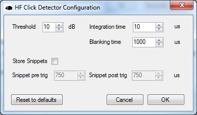
detection can be made. This blanking-time is useful to avoid detecting echoes from a click or to
prevent detecting a large number of clicks if an animal is buzzing near the recorder.

4.1.2 Snippet extractor
For each detection, an entry is added to the detection log and a snippet of wideband sound
surrounding the detection time is saved. The snippet starts and ends a user-selectable time before
and after the detection (user parameters: pre-trigger and post-trigger). Evidently, saving longer
snippets per detection means that the memory is used up more rapidly so this feature allows the
user to trade-off the amount of context that is saved for each detection against the total recording
time. It is important to note that the snippet is taken from the whitened sound and so is high-pass
filtered.

4.1.3 User parameters
The user parameters can be set by clicking the ‘Configure’ button in the Detector section.

Threshold: The level in dB that the power-in-band must exceed the ambient noise level by for a
detection to take place. A value of 12 dB will have a high detection rate but will produce many false
positives. A value of 20 dB will detect only strong transients that are well above the ambient noise
floor.

Integration Time: Set this to the approximate duration of the clicks of interest. For most delphinids
you would use a short averaging time, e.g., 70 µs, while for beaked whales, porpoises and NBHF
delphinids, an averaging time of 150-300 µs would be appropriate. If you are interested in detecting
any toothed whale click, you can either go with a long averaging time (which will reduce the SNR of
short transients and so give poorer detection of delphinids) or an intermediate value which will tend
to reduce sensitivity to both short and long transients but not by much.

Blanking time: Time that must then elapse after a detection before another detection can be made.
Useful to avoid detecting echoes from a click or to prevent detecting a large number of clicks if an
animal is buzzing near the recorder.

Store Snippets: Select to enable storage of detection snippets.

Snippet pre- and post-trigger durations: The time with respect to the detection at which the snippet
will be taken. The snippet starts pre-trigger seconds before the detection and ends post-trigger
seconds after the detection. These are both limited to 1.5 ms maximum which is more than long
enough to cover odontocete clicks. The number of samples saved per snippet is determined by the
sum of the pre- and post-trigger times. With the maximum settings, 1728 samples will be saved per
snippet.

4.1.4 Output File formats
The ST click detector produces two additional output files per recording with suffixes 'bcl' and 'dwv'.
These are in addition to the .wav and .xml files generated normally. The Pamguard interface
automatically interprets these files when displaying detection and continuous recording results. For
users interested in accessing the data using other interfaces, the details of the file formats are given
below:

    •    xml     This is the metadata file produced by SoundTrap to document each recording. The
         ST detector adds metadata about the detector and the user settings to this file.
    •    wav     This is a Microsoft WAV format file containing the decimated continuous sound
         recording produced in parallel with the detector. The sampling rate is selected by the user
         but would typically be 48kHz or 96kHz to maximize recording time. By default, sound data is
         compressed in the SoundTrap using the lossless X3 compressor but this is transparent to the
         user: the .wav file contains the reconstituted uncompressed data.
    •    dwv     This is a Microsoft WAV format file containing the wideband sound snippets for each
         detection. The sampling rate is 576 kHz and the snippets are arranged contiguously with a
         constant number of samples per snippet. The size of each snippet is set the by the pre- and
         post-trigger user parameters. The snippet size in samples will be close to
         round((pre+post)*576e3) but the precise sample count can be found in the .xml file (see the
         Matlab tools for an example of how to extract this information automatically). By default,
snippet sound data is compressed using the lossless X3 compressor but this is transparent to
the user: the .dwv file contains the reconstituted uncompressed data. Up to 100000 snippets
will be saved per recording (i.e., per output file). If more detections are made over this
interval, they will be reported in the BCL file (see below) but no snippet will be saved. This
puts an upper limit on the memory usage rate making it easier to calculate for how long the
SoundTrap will be able to record.
• bcl This is a comma-separated-variable (CSV) text file containing information about
detections. Each line has 7 columns with the following format:
Seconds (in Unix seconds), Microseconds, Report type, Info1,Info2,Info3,Info4,
To obtain high enough resolution, timing information is spread over two fields (Seconds and
Microseconds). The time of each entry is then Seconds+Microseconds/1e6. The four Info
fields are determined by the report type of which there are two. Detections have a report
type of 'D'. The next two fields (Info1 and Info2) indicate whether a snippet was saved (1 or
0) and the noise level at the time of the detection. Fields Info3 and Info4 are not used in
detection reports. The second report type is an effort report which has a type of 'E'. The
effort report indicates the times over which the detector was operating. There will usually
be an on-effort report at the start of each recording (i.e., with a detector state of 1) and an
off-effort report at the end of each recording. The on-effort report has no other data and so
appears as: seconds,microseconds,E,1,,,
The off-effort report appears as: seconds,microseconds,E,0,noise level,ndets,nsaved,
where ndets is the total number of detections made since going on effort and nsaved is the
number of these for which snippets were saved. In both report types, the noise level is given
in Centibels, i.e., 100 log10(p) where p is the noise power referenced to the recorder
calibration. The absolute threshold used for each detection is then p+10^(RDT/10). If no
detections were made throughout a recording, the BCL file will contain two lines:
start_time,microseconds,E,1,,,
end_time,microseconds,E,0,noise level,0,0
If there are detections, they will be bracketed between these lines and the appropriate
detections counts will be changed in the off-effort report. The BCL file can be read anddisplayed by Excel, Libre Office, Open Office etc. See also the Matlab tools for a function to
read this file format.
4.1.5 Click Detector Caveats and Cautions
While every care has been taken in producing the SoundTrap Click Detector, this is free software
offered ‘as is’, in the hope that it will be useful: there is no warranty, implied or otherwise, nor
implication of fitness for any particular purpose. Please use responsibly! Test that the code functions
correctly on your SoundTrap before deploying it, e.g., by setting the RDT to 12 dB and then tapping
lightly on the hydrophone with a finger nail. Even if the code is functioning, it may not detect clicks
because of poor signal-to-noise ratio, because of inappropriate user settings, or because of a poor
mooring design (the same problems that would give you a bad continuous recording).You can also read