STATE OF NORTH CAROLINA - DEPARTMENT OF ADMINISTRATION STATE CONSTRUCTION OFFICE - GUIDELINES AND POLICIES - NC.gov
←
→
Page content transcription
If your browser does not render page correctly, please read the page content below
Fire Alarm Guidelines

                   STATE OF NORTH CAROLINA
                   DEPARTMENT OF ADMINISTRATION
                        STATE CONSTRUCTION OFFICE

                                Fire Alarm

                         GUIDELINES AND POLICIES

                                       2020

                                 -1-
Fire Alarm Guidelines
Instruction to Designers:
1. Designers for State projects involving fire alarm systems shall use and follow the Department of
Administration document “Fire Alarm Guidelines and Policies” only for preparing the designer’s plans
and specifications for the specific project in their contract. The document is not written in contractual
language for bidding purposes and/or contract enforcement. Therefore, the designer is not to insert
the document as is into the specifications. (The Designers can copy from the Guidelines applicable
sections and paste to project written specifications.)
2. It is the Engineer’s responsibility to read and comply with all relevant criteria in the SCO Fire Alarm
Guidelines and Policies. These Guidelines and others are available at the State Construction
Office web site http://www.nc-sco.com/ . Any design noncompliance with the Fire Alarm
Guidelines and Policies resulting in a change order shall be the responsibility of the designer.
3. Clarification: When expressions are shown between two forward slanted lines, the Designer is to
select the most appropriate expression. Example: //Provide photoelectric smoke detection,
ionization smoke detection and rate of rise thermal detection. //
The definition for Total (Complete) Coverage was moved to 17.5.3.1
2013 NFPA 72 requires low frequency (nominal 520 Hz) for audible annunciation in sleeping areas.
This does not include hall ways and common areas outside the bed rooms within residence suites.
-2-Fire Alarm Guidelines
TABLE OF CONTENTS
A. Part 1- General
1. Fire Alarm System in State Owned Facilities ------------------------------------------------ 5
2. Document Specific -------------------------------------------------------------------------------- 5
3. Furnishing, Installation & Connection of the System ---------------------------------------- 5
4. Applicable Codes ---------------------------------------------------------------------------------- 5
5. Fire Alarm Control Panel ------------------------------------------------------------------------- 5
6. Secondary Power ------------------------------------------------------------------------------- 5
7. Quality Assurance ---------------------------------------------------------------------------------- 5
8. Code and Standards --------------------------------------------------------------------------- 6
9. Definition --------------------------------------------------------------------------- 6
10. Submittals --------------------------------------------------------------------------- 7
B. Part 2- Products
1. Fire Alarm Control Panel ----------------------------------------------------------------- 9
2. Alarm Appliances --------------------------------------------------------------------- 14
3. Initiating Devices ----------------------------------------------------------- 15
4. Miscellaneous System items ------------------------------------------------------------ 18
5. Wiring --------------------------------------------------------------- 21
C. Part 3- Execution
1. Fire Alarm System -------------------------------------------------------------------------- 22
2. Fire Alarm Control Equipment Installation ---------------------------------------------------- 22
3. Surge Protection ---------------------------------------------------------------------------- 23
4. Signal Line Circuits -------------------------------------------------------------------------------- 23
5. AC Power ----------------------------------------------------------------------------- 24
-3-Fire Alarm Guidelines
6. Conduit and Wiring ------------------------------------------------------------------------ 24
7. Addressable Pull Stations ----------------------------------------------------------------------- 26
8. Notification Devices ------------------------------------------------------------------------- 26
9. Detectors ---------------------------------------------------------------------------------- 28
10. Duct Mounted Smoke Detectors ------------------------------------------------------------- 29
11. Linear Beam Smoke Detectors ------------------------------------------------------------- 29
12. Printer ------------------------------------------------------------------------------------ 29
13. Air Handler Unit (AHU) Shutdown ---------------------------------------------------------- 29
14. Annunciator ---------------------------------------------------------------------------------- 30
15. Alarm Verification for Smoke Detectors -------------------------------------------------- 30
16. Emergency Voice/Alarm Communication ------------------------------------------------- 31
17. Remote Alarm Transmission Requirements ---------------------------------------------- 32
18. Automatic Smoke door and Automatic Lock Requirements --------------------------- 34
19. Sprinkler System Monitoring ---------------------------------------------------------------- 34
20. Kitchen Exhaust Hood Extinguishing Systems -------------------------------------------- 34
21. Fire Alarm System Installation and Configuration ---------------------------------------- 35
22. Fire and Life Safety Criteria for Doors Controlled by Fire Alarm System ------------ 35
23. System Documentation, Training, and Maintenance ----------------------------------- 36
24. Spare Parts --------------------------------------------------------------------------------------- 39
25. System Testing & Certification ------------------------------------------------------------------ 39
26. Pre-Final Inspection -------------------------------------------------------------------------- 41
27. Final Inspection ----------------------------------------------------------------------------- 41
28. Reacceptance Testing ---------------------------------------------------------------------------- 42
D. PART 4 – Mass Notification ---------------------------------------------------------------------- 42
APPENDIX
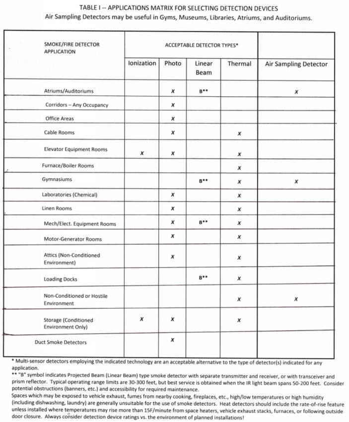
Table 1 Applications Matrix for Selection Detection Devices ---------------------------------- 44
-4-Fire Alarm Guidelines
Fire Alarm System Symbols ------------------------------------------------------------------------ FA- 01
Fire Alarm Riser (Example) ------------------------------------------------------------------------------ FA-02
Fire Alarm Riser Notes (Example) ------------------------------------------------------------------- FA-03
Fire Alarm Matrix (Example) -------------------------------------------------------------------------- FA-04
Transient Arrestor Installation Detail --------------------------------------------------------------- FA-05
Part 1- General *
1. This document is to help assure that the fire detection and alarm systems installed in State Owned
facilities are reliable, maintainable, and have a long service life.
2. This document does not constitute a complete design specification and must be edited and
supplemented with project-specific requirements written by the design professional.
3. This document includes the furnishing, installation, and connection of the microprocessor
controlled; intelligent reporting fire alarm equipment required to form a complete coordinated
system ready for operation. It shall include, but not be limited to, alarm initiating devices, alarm
notification appliances, control panels, auxiliary control devices, annunciators, power supplies, and
wiring.
4. The fire alarm system shall comply with applicable provisions of the NC Building Code,
NFPA 70 - National Electrical Code (NEC), NC Fire Code, and NFPA 72 -National Fire Alarm and
Signaling Code. The Contractor shall furnish all parts, materials, and labor customarily required or
provided for a complete and operating system, in accordance with all requirements applicable,
even if each needed item is not specifically shown or described in the project plans or
specifications
5. The Fire Alarm Control Panel (FACP) shall be located for convenient, rapid access. When
not located in a public or normally occupied area, a Remote Annunciator (FAA) with audible-visible
trouble indication is required. Consult with facility manager and the local fire official, prior to
locating the FACP, FAA or printer. If there is no constantly attended station, locate the FACP or
FAA in a lobby or a corridor adjacent to the entrance used by responding personnel.
6. Systems are to be provided with a separate and independent source of secondary power. The
State does not contract for full Central Station Service (with runners), so all systems that report to
a Central or Remote Supervising Station shall have a minimum of 60 hours battery power capacity,
plus 5/15 minutes of full alarm load.
a) When automatic starting generator is provided and the FACP is powered by the generator, use 24
hours for battery endurance, plus the appropriate (5 or 15 minutes) alarm load.
* If system is being installed to replace an existing system verify that the Drawings detail the scope of any demolition
that may be required. Address any items that may be reused in the new system.
-5-Fire Alarm Guidelines
7. QUALITY ASSURANCE
a) Manufacturer's Qualifications: Firms regularly engaged in manufacture of fire alarm
systems of types, sizes, and electrical characteristics required, and whose products are
Listed and Labeled. Products of firms that do not maintain factory authorized service
organization and spare parts stock are not acceptable for use on State Owned Buildings.
b) Acceptable Manufacturers: Designers shall list minimum of three manufacturers based on
discussions with owner.
d) Installer’s Qualifications: Company specializing in performing the work and making the final
terminations and connections. Minimum of 5 years documented experience installing fire
detection and alarm systems similar in size and scope to the project. Only the Installer may make
program changes and must be present for the 100% test, Designer’s pre-final review and Owner
inspections.
e) All connections to the FACP and the system's programming shall be done only by the manufacturer,
or by an authorized distributor that stocks a full complement of spare parts for the system. The
technicians are required to be trained and individually certified by the manufacturer, for the FACP
model/series being installed. This training and certification must have occurred within the most
recent 24 months, except that a NICET Level III certification will extend this to 36 months. Copies of
the certifications must be part of the Shop Drawing submittal to the Designers, prior to installation.
The submittal cannot be approved without this information.
f) The person that programmed the system must be present for the Engineer’s and State
Construction Office final inspection.
8. Codes and Standards:
a) NFPA Compliance: Comply with applicable requirements of NFPA-72, National Fire Alarm and
Signaling Code.
b) NEC Compliance: Comply with applicable requirements of NFPA-70, National Electrical Code (NEC)
standards pertaining to fire alarm systems.
c) Comply with applicable requirements of NC Building Code and NC Fire Code.
d) Testing Laboratory Compliance: Comply with provisions of UL safety standards pertaining to fire
alarm systems. Provide products and components which are Listed and Labeled.
e) FM Compliance: Provide fire alarm systems and accessories which are FM approved.
9. Definitions:
a) For State-owned facilities in North Carolina the AHJ for Code compliance is the NC Department of
Administration – State Construction Office. The AHJ for construction administration and inspection
purposes is the entity that contracted for the design services, either the State Construction Office
or the owning Agency, as applicable. (Fire alarm system inspection or acceptance testing may be
delegated to the design engineer by contract.)
-6-Fire Alarm Guidelines
b) For Community College or local government projects the AHJ is the local government entity that
approves project plans, issues building permits, and inspects construction.
c) Mass Notification: A complete emergency communications system consisting of emergency
communications control unit (ECCU) and associated components as defined and installed to meet
requirements of NFPA 72. The fire alarm system may include mass notification if it has approved
third party listing and label. Mass notification may be a separate system from Fire Alarm. See
definition in NFPA 72 3.3.87.
d) Building Permits: State Construction Office (SCO) ID Number serves as the permit for construction
or renovation of facilities that are funded by the State of North Carolina and located on State-
owned land. However, privately funded projects on land leased from the State (e.g., student
housing) must still be submitted to local building officials for approval, permits, and inspections.
Written NCDOA/SCO approval of the plans and specifications submitted for review is considered
the equivalent of a building permit for State projects but that alone does not give authorization to
proceed with construction. Such authorization requires written clearance from the entity that
administers the contract.
e) Fire Alarm Control Panel (FACP) - Also called a Fire Alarm Control Unit (FACU) by some entities. See
requirements in Part 2
f) Remote Annunciator (FAA) – Provides LCD display with a text statement of the panel status and/or
LED lamps to indicate the status of the fire alarm system. It is provided to assist fire fighters who
respond to a call and to assist technicians who respond to a trouble condition.
g) Graphic Annunciator (GA) – Used to provide information regarding the status of detection,
sprinkler and supervisor devices by zone and or floor of the building.
10. SUBMITTALS:
a) General: Design document submittals to State Construction Office shall Include all design
information required by North Carolina Building Code and North Carolina Fire Prevention Code.
Design submittals shall address interface with other significant electrical subsystems (e.g.
electrically controlled smoke dampers, door holders, smoke evacuation and smoke control
systems, security lock door hardware, etc.). The designer shall provide a chart of expected
subsystem devices with associated electrical loads, current draw, voltage drop calculations.
Indicate if any subsystems will receive power from fire alarm system via relays or modules. Do not
delegate these design decisions to the contractor. Coordinate as required with other members of
the design team as required for the information.
b) SCO does not review contractor shop drawings. The engineer of Record has responsibility to
review and approve shop drawings.
c) Shop Drawings:
(1) The fire alarm contractor shall submit complete Shop Drawings to the engineer for review, prior
to performing any work. They shall clearly demonstrate compliance with the engineer’s plans and
specifications, which have a System Response Matrix showing the fire alarm system's actions
(outputs) required for each type of alarm, supervisory, and trouble signal. Any non-compliant
features must be fully described.
-7-Fire Alarm Guidelines
(2) Shop drawing submittals shall provide mA draw for each device submitted and the listed
minimum voltage required to operate. Panel submittal shall list voltage drop allowed for panel
and for individual NAC circuits.
(3) The submitted shop drawings shall show equipment, device identification numbers and locations,
and connecting wiring of entire fire alarm system. Include wiring and riser diagrams. Wiring
diagrams shall be based on the project floor plans, with devices and proposed conduit routing.
The conductor composition for each conduit section shall be provided. The distance and route for
each NAC (Notification Appliance Circuit) shall be shown. Riser diagrams shall show consecutive
connections for all devices with addresses and candela and Candela ratings.
(4) Engineer’s approval (with or without corrections) of contractor’s Shop Drawings, samples, cut
sheets, etc., is for general conformance with the contract documents and design concept. It shall
not relieve the contractor of responsibility for full compliance with the project plans and
specifications, EXCEPT for any specific non-compliant features for which the engineer gives
written authorization.
d) Installation Instructions: The contractor shall submit to the engineer of record the
Manufacturer's detailed installation instruction for the Fire Alarm Control Panel and all duct
mounted smoke detectors, flow switches, tamper switches, supervisory switches, and similar items
which require mechanical installation.
e) Battery Calculations:
(1) Include a copy of system battery sizing calculations with the shop drawing submittal to the
engineer. Use manufacturer's battery discharge curve to determine expected battery voltage
after 60/24 hours of providing standby power. Then use calculated Notification Appliance Circuit
current draw in the alarm mode to determine expected voltage drop at End of the Line Resistor
(EOL), based on conductor resistance per conductor manufacturer's data sheet or NEC.
(2) Fire Alarm Vendor’s calculations must be submitted with the shop drawings, and prior to
installation of equipment. (Buildings without generators require minimum 60 hours of battery
backup to cover the weekends and major power outages. Buildings with generators require
minimum 24-hour battery backup.) In the submittal package identify Notification Appliance
Circuits (NAC) current draws and voltage drops for each circuit. Vendor must utilize the “end of
line” method for voltage drop calculations. The “mid-point” method is not acceptable. In no case
shall the calculated voltage at any notification appliance fall below the minimum listed operating
voltage for the devices used.
(3) The voltage drop at EOL must not exceed 14% of the expected battery voltage, after the required
standby time plus alarm time. (Typically, for a 24-volt system, this limits the voltage drop from
the battery to the EOL to 3 volts). Determine "worst case" voltage at far end of each NAC, by
subtracting its calculated V-drop from the expected battery voltage. The result must be no less
than the minimum listed operating voltage for the alarm notification appliances used. All these
calculations must be placed on a dedicated sheet of as-built drawings, for future reference by fire
alarm service technicians.
-8-Fire Alarm Guidelines
(4) Provide copies of battery and voltage drop calculations at SCO final inspection.
f) Maintenance Data: The contractor shall submit maintenance data and parts lists for each type of
fire alarm equipment installed, including furnished specialties and accessories. Include this data,
product data, and shop drawings in maintenance manual.
g) Maintenance Contract: (this paragraph shall be included in the specs ONLY if the Owner/agency do
not have program in place for maintenance) The contractor shall submit a quote for a maintenance
contract to provide all maintenance, test, and repair described below and/or in accordance with
NFPA-72, "Guide for Testing Protection Signaling Systems". Include also a quote for unscheduled
maintenance/repair, including hourly rates for technicians trained on this equipment, and response
travel costs. Submittals that do not identify all post contract maintenance costs will not be
accepted. Rates and costs shall be valid for the period of two (2) years after expiration of the
guaranty. Maintenance and testing shall be on a semiannual basis or as required whichever is the
most restrictive. A preventive maintenance schedule shall be provided by the Contractor that shall
describe the protocol for preventive maintenance. The schedule shall include:
(1) Inspection and testing of the fire alarm system in accordance with the requirements of NFPA 72
Chapter 14
h) Certifications:
(1) Submit a certification from the major equipment manufacturer indicating that the proposed
supervisor of installation and the proposed performer of contract maintenance is an authorized
representative of the major equipment manufacturer. Include names and addresses, and
telephone numbers in the certification.
(2) Installer’s training certificate as defined under Quality Assurance.
i) Existing Fire Alarm System to be replaced with new system in occupied building shall continue to be
operational until the new Fire Alarm System is up and running, otherwise, 24hrs Fire watch shall be
provided per NC Fire Code.
PART 2 - PRODUCTS
1. FIRE ALARM CONTROL PANEL (FACP)
a) FACP - General: The FACP shall meet the following general requirements (unless otherwise required
by the owner for certain systems):
(1) The system is to be the addressable type, with a 24vdc nominal operating voltage.
(2) The system is to have multiple access levels, so owner's authorized personnel can disable
individual alarm inputs or normal system responses (outputs) for alarms, without changing the
system's executive programming or affecting operation of the rest of the system. The process on
how to do this must be included in the training required to be given to the owner's designated
personnel and must also be part of the written documentation provided by the fire alarm
equipment supplier.
-9-Fire Alarm Guidelines
(3) Signal Line Circuits: (SLC) also called addressable loop - Alarm, trouble and supervisory signals
from all intelligent reporting devices shall be encoded onto an NFPA Style 6 (Class A) Signaling
Line Circuit (SLC) with no “T” taps.
(4) Initiation Device Circuits: Initiation Device Circuits (IDC) shall be wired Class B. See NFPA 72 for
definition of Initiating Device Circuit.
(5) Notification Appliance Circuits: Notification appliance circuits shall be wired Class B.
(6) Digitized electronic signals shall employ check digits or multiple polling. In general, a single
ground or open on any system signaling line circuit shall not cause system malfunction, loss of
operating power, or the ability to report an alarm.
(7) Loss of Power: Alarm signals arriving at the main FACP shall not be lost following a power failure
(or outage) until the alarm signal is processed and recorded.
(8) The FACP must have an Alarm Silence switch and be equipped with the Subsequent Alarm (alarm
resound) feature. Any remote annunciators or graphic displays located away from the alarm area
must also include an audible signal with alarm resound feature.
b) System Response to an Alarm Condition: When a fire alarm condition is detected and reported by one
of the system initiating devices or appliances, the following functions shall immediately occur:
(1) The system alarm LED shall flash.
(2) A local piezo-electric signal in the control panel shall sound.
(3) An 80-character minimum LCD display shall indicate all information associated with the fire alarm
condition, including the type of alarm point and its location within the protected premises.
(4) On systems equipped with a printer, printing and history storage equipment shall log the
information associated with each new fire alarm control panel condition, along with time and
date of occurrence.
(5) All system output programs assigned via control-by-event equations activating a particular point
in alarm shall be executed, and the associated system outputs (alarm notification appliances
and/or relays) shall be activated. Exact programming shall be provided by the Contractor to
meet the Owner’s requirements.
(6) Detect activation of any initiating device and the location of the alarm condition. Operate all
notification appliances and auxiliary devices as programmed.
(7) Activate all fire alarm Notification Appliances in the building, sounding and flashing in
synchronization continuously until the initiating device and control unit have been reset to
normal condition.
(8) Activate digital alarm communicator.
(9) Deactivate door hold control relay such that all smoke doors close.
- 10 -Fire Alarm Guidelines
(10) Deactivate control relays so that HVAC units shut down. Exception is for hazardous exhaust
systems and smoke control.
(11) Activate elevator recall sequence if smoke is detected in any elevator lobby, shaft, or in the
elevator equipment room.
(12) Activate control relay(s) to release all magnetically locked egress doors.
c) System Response to a Trouble Condition:
(1) Systems AC power trouble signal shall not be sent unless maintained for 1 to 3 hours (or more)
Provide additional relays as required for this purpose.
(2) Provide immediate transmission of all other supervising signals.
(3) Provide adjustable time delay for all other trouble signals prior to transmission.
(4) FACP - Minimum Requirements: The FACP shall contain a microprocessor based Central
Processing Unit (CPU). The CPU and its associated equipment shall be protected so it cannot be
affected by voltage surges or line transients consistent with UL standard 864. The CPU shall
communicate with and control the following types of equipment used to make up the system:
intelligent detectors, addressable modules, local and remote operator terminals, printers,
annunciators, and other system-controlled devices. The main FACP shall perform the following
functions:
(5) Supervise and monitor all intelligent addressable detectors and monitor modules connected to
the system for normal, trouble and alarm conditions.
(6) Supervise all initiating, signaling, and notification circuits throughout the facility by way of
connection to monitor and control modules, or end of line resistor.
(7) Visually and audibly annunciate any trouble, supervisory or alarm condition on operator's
terminals, panel display, and annunciators.
d) System Capacity and General Operation: SCO approved system design shall have the following
capacities and general operation modes:
(1) The FACP shall provide or be capable of expansion to 198 intelligent/addressable devices per
Signaling Line Circuits (SLC) and 1980 initiating points, minimum, per system. The number of
SLCs provided shall be as indicated on the Drawings. Total points shall be as indicated on the
drawings or otherwise specified with minimum 20% spare capacity.
(2) The FACP shall include a full featured operator interface control and annunciation panel that
shall include a backlit, 80 minimum character liquid crystal display, individual, color coded
system status LEDs, and an alphanumeric keypad for the field programming and control of the
fire alarm system.
(3) All programming or editing of the existing program in the system shall be achieved with a
personal computer on site. A copy of the database shall be left in the Document Box per NFPA
72.
- 11 -Fire Alarm Guidelines
(4) Notification Appliance Circuits with 20% spare capacity.
e) The FACP shall be able to provide the following features:
(1) Upload/Download to PC Computer
(2) Charger Rate Control
(3) Drift Compensation
(4) Automatic Day/Night Sensitivity Adjust
(5) Device Blink Control
(6) Pre-alarm Control Panel Indication
(7) Trouble Reminder
(8) NFPA 72 Smoke Detector Sensitivity Test
(9) System Status Reports
(10) Periodic Detector Test
(11) Alarm Verification, by device, with tally
(12) Non-Alarm Module Reporting
(13) Block Acknowledge
(14) Smoke Detector Maintenance Alert
(15) Control-By-Time
f) The control panel shall be capable of printing historical data and device parameters and shall include
all equipment necessary to produce printouts, including an external printer and shall be listed as
meeting the NFPA 72 sensitivity testing and maintenance requirements without the need for manually
removing and testing each smoke detector. The control panel shall provide a display and a printed list
of these sensitivity measurements as a permanent record of the required sensitivity testing. The
system shall also annunciate a trouble condition when any smoke detector approaches 80% of its
alarm threshold due to gradual contamination, with an annunciation of the location of the smoke
detector requiring service. If any specialized equipment must be used to program any function of the
smoke detector devices, then one must be furnished as part of the system.
g) The system shall perform time-based control functions including automatic changes of specified
smoke detector sensitivity settings.
h) Central Processing Unit: The Central Processing Unit (CPU) shall communicate with, monitor, and
control all other modules within the control panel. Removal, disconnection or failure of any control
panel module shall be detected and reported to the system display by the CPU.
- 12 -Fire Alarm Guidelines
(1) The CPU shall contain and execute all control-by-event (including ANDing, ORing, NOTing,
CROSSZONEing) programs for specific action to be taken if an alarm condition is detected by the
system. Such control-by-event programs shall be held in non-volatile programmable memory
and shall not be lost with system primary and secondary power failure. The CPU shall also
provide a real-time clock for time annotation of all system displays. The Time-of-Day and date
shall not be lost if system primary and secondary power supplies fail.
(2) The CPU shall be capable of being programmed on site without requiring the use of any external
programming equipment. Systems that require the use of external programmers or change of
EPROMs are not acceptable.
i) Operators Control: Provide an operator’s interface which allows the following minimum functions. In
addition, the operator’s interface shall support any other functions required for system control and/or
operation:
(1) Acknowledge (ACK/STEP) Switch
(2) Signal Silence Switch
(3) System Reset Switch
(4) System Test Switch
(5) Lamp Test Switch
(6) Programmable, supervised switches for fire safety function bypasses. i.e. NAC Bypass, Elevator
Capture Bypass, HVAC Shutdown Defeat, Smoke Control Bypass, etc. Switch operation shall be
password protected.
j) Display: The system display shall provide all the controls and indicators used by the system
operator and may also be used to program all system operational parameters. The display assembly
shall contain, and display as required, custom alphanumeric labels for all intelligent detectors,
addressable modules, and software zones.
(1) The system display shall provide an 80 minimum -character back-lit alphanumeric Liquid Crystal
Display (LCD).
(2) The Display shall also provide four Light-Emitting-Diodes (LEDs), which will indicate the status of
the following system parameters: AC POWER, SYSTEM ALARM, SYSTEM TROUBLE, and SIGNAL
SILENCE.
(3) The system display shall provide a touch keypad with control capability to command all system
functions, entry of any alphabetic or numeric information, and field programming. Two different
password levels shall be accessible through the display interface assembly to prevent
unauthorized system control or programming.
k) Signaling Line Circuit (SLC) Interface Board: The FACP shall contain SLC interface boards as required to
communicate with the SLC. Each SLC board shall monitor and control a minimum of 198 intelligent
- 13 -Fire Alarm Guidelines
addressable devices. This includes 99 analog detectors (Ionization, Photoelectric, or Thermal) and 99
monitor or control modules.
(1) Each SLC interface board shall contain its own microprocessor and shall be capable of operating
in a local mode (any SLC input activates all or specific SLC outputs) in the event of a failure in the
main CPU of the control panel. The SLC interface board shall not require any jumper cuts or
address switch settings to initialize SLC Loop operations. SLC interface boards shall provide
power and communicate with all intelligent addressable detectors and modules connected to its
SLC Loop on a single pair of wires. This SLC Loop shall be capable of operation as NFPA 72 Class A
(Style 6) or Class X (Style 7).
(2) Each SLC interface board shall receive analog information from all intelligent detectors and shall
process this information to determine whether normal, alarm, or trouble conditions exist for
that specific detector. The SLC interface board software shall include software to automatically
maintain the detector's desired sensitivity level by adjusting for the effects of environmental
factors, including the accumulation of dust in each detector. The analog information may also be
used for automatic detector testing and for the automatic determination of detector
maintenance requirements.
l) Printer: Provide a printer to provide hard-copy printout of all changes in status of the system. The
printer shall timestamp such printouts with the current time-of-day and date. The printer shall be
standard carriage with 80-characters per line and shall use standard pin-feed paper. Thermal printers
are not acceptable. The printer shall operate from a 120 VAC, 60 Hz power source. Provide table and
stand for printer if it is to remain constantly connected to the fire alarm panel.
m) Remote Transmissions: The FACP shall be interfaced to a Digital Alarm Communications Transmitter
(DACT). See requirements in NFPA 72, 26.6 for acceptable means to transmit fire alarm signals.
n) Power Supply: The FACP power supplies shall operate on 120 VAC, 60 Hz and shall have a continuous
rating adequate to power all equipment and functions in full alarm continuously. All modules and
drivers must be able to withstand prolonged short circuits in the field wiring, either line-to-line or line-
to-ground, without damage. Further, the power supply shall be expandable for additional notification
appliance power in 3.0 Ampere increments.
o) The power supply shall provide a battery charger using dual-rate charging techniques for fast battery
recharge.
p) Batteries: Shall be completely maintenance free, shall not require liquids, fluid level checks or
refilling, and shall not be capable of producing spills and/or leaks. Batteries shall be sealed gel-cell
type with expected life of 10 years. Battery voltage shall be as required by the FACP and related
equipment. Battery shall have enough capacity to power the fire alarm system for not less than
//24//60// hours plus // 5 // 15 // minutes of alarm upon a normal AC power failure. NAC circuits
shall not exceed 75% of maximum current load allowed. (For batteries serving emergency voice
communications the duration of alarm reserve shall be 15 minutes in lieu of 5 minutes)
q) Enclosures: The FACP shall be housed in a 3rd party listed cabinet suitable for surface or semi-flush
mounting. Cabinet and front shall be corrosion protected, given a rust-resistant prime coat, and
manufacturer's standard finish. The door shall provide a key lock and shall include a glass or other
- 14 -Fire Alarm Guidelines
transparent opening for viewing of all indicators. For convenience, the door may be hinged on either
the right or left side (field selectable).
2. ALARM APPLIANCES
a) Programmable Electronic Sounders: Sounders located outdoors shall be listed for use in wet locations.
Electric sounders shall operate with synchronized audible output and have the following
specifications:
(1) Voltage: Programmable electronic sounders shall operate on 24 VDC nominal.
(2) Programming: Electronic Sounders shall provide the ANSI S3.41 three-pulse temporal pattern
audible evacuation signal, described in NFPA 72, with an output sound level of at least 90 dBA
measured at 10 feet from the device. Output sound level shall be 110 dB maximum. Electronic
Sounders shall be field programmable without the use of special tools.
b) Strobe Lights shall be located as shown on the Drawings. Strobe lights indicated for use exterior to the
building shall be mounted at the indicated elevation and listed for use in wet locations. Strobe lights
shall operate with synchronized flash output and have the following specifications:
(1) Voltage: Strobe lights shall operate on 24 VDC nominal.
(2) Maximum pulse duration: 2/10ths of one second.
(3) Strobe intensity and flash rate: Must meet minimum requirements of UL 1971. Provide strobe
lights with minimum intensity Candela (Cd) rating of 15 Cd, or greater if such is indicated
adjacent to the device symbol on the Drawings. The Fire Alarm Contractor shall verify all candela
settings prior to conducting the voltage drop testing required later in this document. Contractor
shall also verify the design candela settings are adequate for the space being covered. Care must
be taken to assure the devices are mounted in the exact locations shown on the approved shop
drawing documents. Notify the designer of any deficiencies.
c) Speakers: Speakers, where provided, shall have audible sound with taps at 1/4-watt, 1/2-watt, 1-watt,
2-watts. Speakers shall operate at // 70.7V // 25 V //. Provide back boxes for all speakers. Speakers
shall be tapped at 1 watt for design purposes. See additional requirements for Programmable
Electronic Sounders.
d) Horns: Where provided, shall provide a sound level of 15 dBA above ambient as listed in the NFPA 72.
e) Horns and sounder bases in bedrooms or other sleeping rooms shall operate at 520-Hz with frequency
tolerance permitted in NFPA 72.
f) Audible/Visual Combination Devices shall comply with all applicable requirements for both
Programmable Electronic Sounders and Strobe Lights.
g) Bells shall be 10" diameter vibrating type located as shown on the Drawings; bells located outdoors
shall be listed for use in wet locations. Bells shall have the following specifications:
Voltage: Bells shall operate on 24 VDC nominal.
- 15 -Fire Alarm Guidelines
3. INITIATING DEVICES
a) Addressable Devices - General: All initiating devices shall be individually addressable. Addressable
devices shall comply with the following requirements:
(1) All addressable spot type and duct smoke detectors shall be the analog type and the alarm
system shall automatically compensate for detector sensitivity changes due to ambient
conditions and dust build-up within detectors. This feature must be armed, and sensitivities set
prior to acceptance of the system.
(2) Address Setting: Addressable devices shall provide an address-setting means.
(3) Connections: Addressable devices shall be connected to a Signaling Line Circuit (SLC) with
minimum two (2) wires.
(4) Operational Indications: Addressable smoke and heat detectors shall provide dual LEDs. LEDs
shall flash under normal conditions, indicating that the device is operational and in regular
communication with the control panel. The flashing mode operation of the detector LEDs shall
be optional through the system field program.
(5) Intelligent Initiation Devices: All smoke detectors shall be the "intelligent" in that smoke
detector sensitivity shall be set through the FACP and shall be adjustable in the field through the
field programming of the system. Sensitivity shall be capable of being automatically adjusted by
the FACP on a time-of-day basis. Using software in the FACP, detectors shall be capable of
automatically compensating for dust accumulation and other slow environmental changes that
may affect performance. The detectors shall be listed by UL as meeting the calibrated sensitivity
test requirements of NFPA Standard 72.
(6) Spot-type detectors must be the plug-in type, with a separate base (not a mounting ring), to
facilitate their replacement and maintenance. The base shall have integral terminal strips for
circuit connections, rather than wire pigtails.
(7) Device mounting Base: Unless otherwise specified all detectors shall be ceiling-mount and shall
include a separate twist-lock base with tamper proof feature.
(8) Sounder Base: Provide bases with a built-in (local) sounder rated at 85 dBA minimum, measured
at 10ft. Configure sounder bases such that sounders are activated under conditions as described
in the Matrix. Provide low frequency sounder bases in sleeping areas.
(9) Test Means: The detectors shall provide a test means whereby they will simulate an alarm
condition and report that condition to the control panel. Such a test may be initiated at the
detector itself (by activating a magnetic switch) or initiated remotely on command from the
control panel when in the "test" condition. Actual or synthetic smoke must be used during the
100% testing to assure smoke entry into the sensing chamber.
(10) Device Identification: Detectors shall store an internal identifying type code that the control
panel shall use to identify the type of device.
- 16 -Fire Alarm Guidelines
b) Photoelectric Smoke Detectors: Photoelectric smoke detectors shall use the photoelectric (light-
scattering) principal to measure smoke density and shall, on command from the control panel, send
data to the panel representing the analog level of smoke density.
c) Ionization Smoke Detector: Ionization smoke detectors shall use the dual-chamber ionization principal
to measure products of combustion and shall, on command from the control panel, send data to the
panel representing the analog level of products of combustion.
d) Thermal Detectors: Thermal Detectors shall be intelligent addressable devices rated at 135°F (58°C)
and shall have a rate-of-rise element rated at 15° F. (9.4°C) per minute. It shall connect via minimum
two wires to the Fire Alarm Control Panel Signaling Line Circuit. Up to 99 intelligent heat detectors
may connect to one SLC loop. Thermal detectors shall use an electronic sensor to measure thermal
conditions caused by a fire and shall, on command from the control panel, send data to the panel
representing the analog level of such thermal measurements.
(1) Non-Rate of Rise Detectors: Provide thermal detectors with non-rate of rise thermal elements.
Non-rate of rise detectors is indicated by NRR adjacent to the thermal detector symbol. Where
used in elevator machine rooms or hoist ways, select temperature rating nominal 10 degrees F
less than the adjacent fire sprinkler.
(2) Specialized Element Temperature Ratings: Provide thermal detectors with specialized element
temperature ratings. Specialized element temperatures are indicated by a temperature rating
adjacent to the thermal detector symbol, e.g. 195°F.
e) Multi-sensor Detectors: Detectors employ two or more of the above detection types with integrated
operating principals, mounted in a single housing. The outputs of the analog sensors shall be
transformed into digital signals that are combined and processed by special algorithms. The
computations shall be designed to discriminate between normal ambient changes in a building and
those changes associated with a fire. //Provide photoelectric smoke detection and rate of rise
thermal detection. //Provide photoelectric smoke detection, ionization smoke detection and rate of
rise thermal detection. //
f) Duct Smoke Detector: In-Duct Smoke Detector Housings shall accommodate a velocity rated
photoelectric detector. The device, independent of the type used, shall provide continuous analog
monitoring and alarm verification from the panel. When enough smoke is sensed, a supervisory or
alarm signal shall be initiated at the FACP. Coordinate with owner for response appropriate for the
location.
g) Addressable Pull Stations - General: Addressable pull stations shall, on command from the Control
Panel, send data to the panel representing the state of the manual switch. They shall use a key
operated test-reset lock and shall be designed so that after actual emergency operation, they cannot
be restored to normal use except using a key. All pull stations shall be dual action, have a positive,
visual indication of operation and utilize a key type reset. The Glass-break rods are not allowed.
Mount pull station with operating mechanism between 42-inches and 48-inches above finished floor.
h) LINEAR BEAM SMOKE DETECTORS
(1) Linear Beam Smoke Detectors shall be configured as an integral part of the Fire Alarm system.
Linear beam smoke detectors shall meet the following requirements:
- 17 -Fire Alarm Guidelines
(2) Linear beam detectors shall have a minimum of three calibrated sensitivity settings capable of
maintaining sensitivity between 1.0% and 2.0% per meter obscuration, at any operating distance
between 10 and 60 meters. (30 feet and 300 feet)
(3) The manufacturer of linear beam detector shall provide a calibration chart giving the Smoke
Sensitivity versus Operating Distance for each sensitivity setting. This chart shall show the 3rd
party listed sensitivity limits for the entire range of rated operating distances.
(4) Linear beam detectors must be rated for continuous operation up to 122°F (50°C) and a 95%
relative humidity.
(5) Compensating circuits must be provided in the detector to maintain normal sensitivity as
environment conditions change and as dust builds up on the lenses. When the limits of this
compensation are reached, a "trouble" signal must be initiated.
(6) Horizontal and vertical adjustments must be provided, on both the transmitter and the receiver,
for alignment of the IR beam. They must permit a minimum angular change of 7.5° from the
center axis, in any direction.
(7) The IR beam must be modulated, to assure reliable operation in the presence of very high
ambient light and/or background IR.
(8) Abrupt, maintained blockage of the IR beam shall result in a "trouble" signal (not alarm), to be
initiated within a time span of 10 seconds minimum to 60 seconds maximum.
(9) Do not mount beam detector components on unsupported walls or structures. Vibration can
cause nuisance trouble and alarm conditions.
I) REMOTE AIR SAMPLING SMOKE DETECTION
(1) Air Sampling detector shall have approved third party listing and label.
(2) Air Sampling Equipment (ASE) shall report all trouble and alarm conditions to building FACP.
Report trouble if airflow changes 20% or greater.
(3) ASE shall have battery backup power matching battery backup in building fire alarm system.
(4) NICET level 3 or higher with certification in ASE pipe network design shall prepare ASE shop
drawings. Include type, size, and dimensions of pipe sections in the pipe network.
(5) Balance each node for number of holes and airflow.
(6) Provide bend connections in piping rather than elbows.
(7) Glue pipe sections except pipes connecting to the detector and exhaust manifold.
(8) Provide end caps on sampling pipes.
(9) Provide report verifying air sampling detector pipe layout balances pneumatically within the
airflow range of the air sampling detector.
(10) Provide label "Smoke Detection Sampling Tube – Do Not Disturb” at changes in direction, on
each side of wall, floor, or other penetrations. Do not exceed 20-feet between labeling.
(11) Label sampling points “Fire Detection System Do Not Paint”
(12) Label the farthest sampling port from the detector “Test Point”.
- 18 -Fire Alarm Guidelines
4. MISCELLANEOUS SYSTEM ITEMS
a) Addressable Dry Contact Monitor Module: Addressable Monitor Modules shall be provided to connect
one supervised zone (either Style D or Style B) of non-addressable Alarm Initiating Devices (any Normally
Open [N.O.] dry contact device) to one of the Fire Alarm Control Panel Signaling Line Circuit Loops.
Monitor modules shall be installed as required by the system configuration. All required monitor
modules may not be shown on the Drawings.
(1) Indication of Operation: An LED shall be provided that shall flash under normal conditions, indicating
that the Monitor Module is operational and in regular communication with the control panel.
(2) Supervision: Unless specifically noted otherwise on the drawings provide one monitor module for
each sprinkler switch.
b) Two Wire Detector Monitor Module: Addressable Monitor Modules shall be provided to connect one
supervised IDC zone, // Class A // B (Style D or Style B operation) //of nonaddressable 2- wire smoke
detectors or alarm initiating devices (any N.O. dry contact device) to one of the Fire Alarm Control Panel
Signaling Line Circuit Loops. Monitor modules shall be installed as required by the system configuration.
All required monitor modules may not be shown on the Drawings. Indication of Operation: Unless
otherwise indicated on the Drawings an LED shall be provided that shall flash under normal conditions,
indicating that the Monitor Module is operational and in regular communication with the control panel.
c) Addressable Control Module: Addressable Control Modules shall be provided to supervise and control
the operation of one conventional Notification Appliance Circuit (NAC) of compatible, 24 VDC powered,
polarized Audio/Visual (A/V) Notification Appliances. For fan shutdown and other auxiliary control
functions, the control module may be set to operate as a dry contract relay. The control module shall
provide address-setting means. An LED shall be provided that shall flash under normal conditions,
indicating that the control module is operational and is in regular communication with the control panel.
If the voltage being controlled is 120 VAC or greater, an isolating 24 VDC relay shall be used.
(1) Configuration: The control module NAC circuit may be wired for // Style Z // Style Y // (Class A/B) //
with up to 1 Amp of inductive A/V signal, or 2 Amps of resistive A/V signal operation, or as a dry
contact (Form C) relay. The control module shall be suitable for pilot duty applications and rated for
a minimum of 0.6 amps at 30 VDC. The relay coil shall be magnetically latched to reduce wiring
connection requirements, and to ensure that 100% of all auxiliary relay or NACs may be energized at
the same time on the same pair of wires. Designer shall confirm the relay contacts are rated for the
attached load.
(2) Power Source: Audio/visual power shall be provided by a separate supervised power loop from the
main fire alarm control panel or from a supervised, 3rd party listed remote power supply. A/V power
sources and connections are not shown on the Drawings.
d) Isolator Module: Isolator Modules shall be provided to automatically isolate wire-to-wire short circuits
on an SLC loop. The Isolator Module shall limit the number of modules or detectors that may be
rendered inoperative by a short circuit fault on the SLC Loop to 20 addressable devices. Modules must
be readily accessible (not above ceiling) and clearly labeled.
- 19 -Fire Alarm Guidelines
(1) Operation: Isolator Modules shall operate such that if a wire-to-wire short occurs, the Isolator
module shall automatically open-circuit (disconnect) the SLC loop. When the short circuit condition is
corrected, the Isolator Module shall automatically reconnect the isolated section. The Isolator
Module’s operations shall be totally automatic.
(2) The Isolator Modules shall provide a single LED that shall flash to indicate that the Isolator is
operational and shall illuminate steadily to indicate that a short circuit condition has been detected
and isolated.
e) Water Flow Switch: Flow switches shall be integral, mechanical, non-coded, non-accumulative retard
type. Flow switches shall have an alarm transmission delay time that is conveniently adjustable from 0 to
60 seconds. Initial settings shall be 30-45 seconds. Flow switches shall be located a minimum of one (1)
foot from a fitting that changes the direction of the flow and a minimum of three (3) feet from a valve as
required per NFPA 13. Installation: Water Flow Switches shall be connected by the Division 16
(Electrical) Contractor but furnished and installed by the Division 23 (Mechanical) Contractor.
f) Sprinkler and Standpipe Valve Supervisory Switch: Supervisory switch mechanisms shall be contained in
a weatherproof housing that shall provide a 3/4-inch tapped conduit entrance and shall incorporate the
necessary facilities for attachment to the valves. Switch housing shall be finished in red baked enamel.
Mounting: Mount switch so as not to interfere with the normal operation of the valve and adjust to
operate within two revolutions toward the closed position of the valve control, or when the stem has
moved no more than one-fifth of the distance from its normal position.
g) Serially Connected Remote Annunciator: Annunciator shall communicate with the fire alarm control
panel via an EIA-485 communications loop (four-wire) and shall individually annunciate all zones in the
system. System zones shall be as indicated on the Drawings. Up to 10 annunciators may be connected
to the EIA-485 communications loop.
(1) Annunciator Indicators: The annunciator shall provide a red Alarm LED per zone, and a yellow
Trouble LED per zone. The annunciator shall also have an "ON-LINE" LED, local piezo sounder,
local acknowledge/lamp test switch, and custom zone/function identification labels.
Annunciator switches may be used for System control such as, Global Acknowledge, Global
Signal Silence, and Global System Reset. All annunciator switches and indicators shall be
software programmable.
(2) LCD Alphanumeric Display Annunciator: The Alphanumeric Display Annunciator shall be a
supervised, remotely located back-lit LCD display containing a minimum of eighty (80) characters
for alarm annunciation in clear English text. The LCD Annunciator shall display all alarms and
trouble conditions in the system.
(3) System Capacity: The system shall allow a minimum of four LCD annunciators. In addition to
annunciation functions, each LCD annunciator shall be capable of the following software
programmed system functions: Acknowledge, Signal Silence and Reset.
(4) Connections: The annunciator shall connect to a two-wire EIA-485 interface. The two-wire
connection shall be capable operation at distances of 6,000 feet. Provide interface to fiber optic
cable systems and/or repeater units where such are indicated on the Drawings.
- 20 -Fire Alarm Guidelines
h) Remote Annunciator Indicator Lights (RAIL): RAILs shall be provided with a key type switch for testing
of the annunciated device. In addition. RAILs shall have the following features: Voltage: RAILs shall
operate on 24 VDC nominal.
i) Door Hold-Open Magnets: Door hold open magnets shall be suitable for mounting in a single gang
electrical device box. Door hold open magnets shall be furnished with keepers, door chains, and other
accessories as required to properly hold open doors as indicated on the Drawings. Holding force of
the magnet shall be appropriate for the door to be held open. Door hold open magnets shall operate
in a fail-safe manner, i.e., the door shall release in event of a failure of voltage to the device. Power
Source: Door hold open magnets shall be configured to operate from a nominal 24 VDC system as
supplied by the FACP or other power supply listed for the purpose. All hold open magnet supply
sources, whether a part of the FACP or whether derived from a separate power supply, shall be
supervised. Door hold open magnet circuits which use step-down transformers, 120 VAC, or local
relays are not permitted. Door shall close within 60 seconds of the power loss.
j) Battery Power Supply (BPS) &/or Supplementary Notification Appliance Circuit (SNAC): These types of
panels shall be completely maintenance free, shall not require liquids, fluid level checks or refilling,
and shall not be capable of producing spills and/or leaks. Batteries shall be sealed gel-cell type with
expected life of 10 years. Battery voltage shall be as required by the FACP and related equipment.
Battery shall have enough capacity to power the fire alarm system for not less than //24 // 60 // hours
plus // 5 // 15 // minutes of alarm upon a normal AC power failure. Battery cabinet shall be twice the
size of the batteries it will contain. NAC circuits shall not exceed 75% of maximum current load
allowed.
k) Surge Protection: The following protection against voltage transients and surges must be provided by
the fire alarm equipment supplier, and installed by the electrical contractor:
(1) On AC Input: A feed-through (not shunt-type) branch circuit transient suppressor such as Leviton
51020-WM-DIN, or Ditek DTK-120SRD 20 Amp or equivalent UL 1449 - Latest Edition Listed
device.
(2) On DC Circuits Extending Outside Building: At a point near entry to the building provide "pi"-
type filter on each leg, consisting of a primary arrestor, series impedance, and a fast-acting
secondary arrestor that clamps at 30v-40v.
Some acceptable models: Simplex 2081-9027, Simplex 2081-9028, Transtector
TSP8601, Ditek DTK 2MHLP24BWB series, Citel America B280-24V, and Northern Technologies
DLP-42. Submit data on others to the engineer for approval. UL 497B listing is normally a
prerequisite for their consideration. Devices using only MOV active elements are not acceptable.
5. Wiring
a) Addressable loop (signaling line) circuits shall be wired with type FPL/FPLR/FPLP fire alarm cable, AWG 18
minimum, low capacitance, twisted shielded copper pair. Cable shield drain wires are to be connected at each
device on the loop to maintain continuity, taped to insulate from ground, and terminated at the FACP.
Acceptable cables include Atlas 228-18-1-1STP, BSCC S1802s19 (same as EEC 7806LC), West Penn D975, D991
(AWG 16), D995 (AWG 14), or equal wire having capacitance of 30pf/ft. maximum between conductors. Belden
5320FJ acceptable if only FPL rating needed. The cable jacket color shall be red, with red (+) and black (-)
conductor insulation.
- 21 -You can also read