Unreliable airspeed indication and stall warning involving Airbus A320, VH-FNP - ATSB Transport Safety Report
←
→
Page content transcription
If your browser does not render page correctly, please read the page content below
Unreliable airspeed indication
 and stall warning involving
 Airbus A320, VH-FNP
 near Perth, Western Australia, on 12 September 2015

ATSB Transport Safety Report
Aviation Occurrence Investigation
AO-2015-107
Final – 4 April 2019
Released in accordance with section 25 of the Transport Safety Investigation Act 2003

Publishing information

Published by:        Australian Transport Safety Bureau
Postal address:      PO Box 967, Civic Square ACT 2608
Office:              62 Northbourne Avenue Canberra, Australian Capital Territory 2601
Telephone:           1800 020 616, from overseas +61 2 6257 4150 (24 hours)
                     Accident and incident notification: 1800 011 034 (24 hours)
Facsimile:           02 6247 3117, from overseas +61 2 6247 3117
Email:               atsbinfo@atsb.gov.au
Internet:            www.atsb.gov.au

© Commonwealth of Australia 2019

Ownership of intellectual property rights in this publication
Unless otherwise noted, copyright (and any other intellectual property rights, if any) in this publication is owned by the
Commonwealth of Australia.

Creative Commons licence
With the exception of the Coat of Arms, ATSB logo, and photos and graphics in which a third party holds copyright,
this publication is licensed under a Creative Commons Attribution 3.0 Australia licence.

Creative Commons Attribution 3.0 Australia Licence is a standard form license agreement that allows you to copy,
distribute, transmit and adapt this publication provided that you attribute the work.

The ATSB’s preference is that you attribute this publication (and any material sourced from it) using the
following wording: Source: Australian Transport Safety Bureau

Copyright in material obtained from other agencies, private individuals or organisations, belongs to those
agencies, individuals or organisations. Where you want to use their material you will need to contact them
directly.

Addendum
    Page                Change                                                                            Date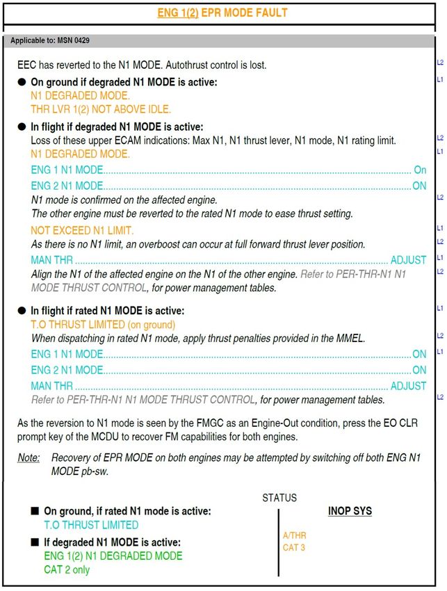
Safety summary
What happened                                                          Airbus A320, VH-FNP
On 12 September 2015, when a Virgin Australia Regional
Airlines Airbus A320 aircraft, registered VH-FNP, was passing
through about 8,500 ft on departure from Perth Airport, Western
Australia, the autothrust and autopilot disconnected, and multiple
alerts were generated. The flight crew continued the climb to an
altitude of 20,000 ft, where they levelled out to troubleshoot the
issues before returning to Perth. During the approach, when the
flight crew were aligning the aircraft with the instrument landing     Source: ATSB

system, they received a stall warning. The warning stopped after
six seconds and the approach continued for a successful landing.

What the ATSB found
The ATSB found that blocked drain holes in the pitot probes prevented water from being
effectively discharged, resulting in erroneous airspeed measurements in all three systems at
various times during the take-off and climb. The erroneous airspeeds were not detected by the
flight crew, but had been detected by the system, resulting in the autothrust and autopilot
disconnecting, and the generation of multiple alerts, including a NAV ADR DISAGREE alert. That
alert required the flight crew to crosscheck the three airspeed indications and the result would
indicate if they had an airspeed or angle of attack disagreement. Due to the limited space in the
alert message area, the NAV ADR DISAGREE alert was initially pushed off the screen by engine
related alerts that were programmed to have a higher priority.
The engine related alerts did not require immediate actions by the flight crew, and because of their
high-workload, the flight crew did not clear them and action the NAV ADR DISAGREE procedure
until after the airspeeds had corrected themselves, and all displayed the same value. This led the
flight crew to diagnose it as an angle of attack disagreement, which the procedure informed them,
had the ‘risk of undue stall warning’. When they received the stall warning during the approach,
the flight crew considered it spurious and disregarded that warning. However, there was nothing
wrong with the angle of attack and the warning was real.
The ATSB also found that the NAV ADR DISAGREE alert and the associated procedure in the
Airbus A320 may lead the flight crew to incorrectly identify the source of the alert (for example,
angle of attack instead of airspeed) when there is a short-term disagreement in the airspeeds.

What's been done as a result
The aircraft manufacturer is in the process of updating the aircraft’s software so that the NAV ADR
DISAGREE alert has a higher priority than the associated engine alerts. In the case of multiple
alerts, it will take precedence over the other associated alerts and be immediately visible to the
flight crew. In addition, the ‘risk of undue stall warning message’ will be removed from the aircraft
status related to the NAV ADR DISAGREE alert.

Safety message
Modern aircraft with multiple interacting systems can have many layers between the source
information and the flight crew. In such systems, where there is erroneous information from an
information source, it is important that alerts and procedures be designed to ensure that the flight
crew can correctly diagnose the source of the erroneous information. This is particularly important
when the information may be erroneous for a short period.
Contents
The occurrence ........................................................................................................................1
Preparation for the flight 1
Take-off and climb 1
Troubleshooting and return to Perth 4
Descent and landing 6
Context ......................................................................................................................................9
Meteorological information 9
Aircraft information 11
Electronic instrument system 11
Park brake 15
Auto flight 15
Power plants 16
Air data reference system 17
Flight control system 19
Centralised fault display system 21
Maintenance information 21
Post-flight troubleshooting 21
Pitot probe maintenance 23
Erratic airspeed indications – maintenance actions 23
Detailed examination of pitot probes 24
Airworthiness directives 25
Operating procedures 26
Normal procedures 26
Abnormal procedures 26
Recorded information 33
Flight data recorder 33
Cockpit voice recorder 34
Manufacturer’s analysis 34
Engine reversion to N1 mode 34
Airspeed estimations 34
Stall warning activation analysis 36
Airspeed anomalies on the ground 36
Manufacturer’s conclusions 37
Other occurrences 37
VH-FNP on 9 September 2015 37
Other indications of airspeed anomalies on VH-FNP 38
Other unreliable airspeed indication occurrences 38
Safety analysis ...................................................................................................................... 41
Introduction 41
Blocked pitot probes and unreliable airspeed indications 41
Diagnosis of the NAV ADR DISAGREE alert source 43
Flight crew workload 43
ECAM alert priorities 44
NAV ADR DISAGREE procedure 44
Stall warning 45
Findings ................................................................................................................................. 46
Contributing factors 46
Other factors that increased risk 46
Additional findings 46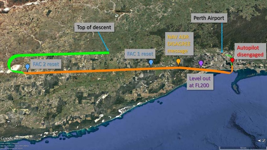
Safety issues and actions ................................................................................................... 47
General details ...................................................................................................................... 49
     Occurrence details                                                                                                                49
     Aircraft details                                                                                                                  49
Sources and submissions .................................................................................................. 50
     Sources of information                                                                                                50
     Submissions                                                                                                           50
Appendices ........................................................................................................................... 51
     Appendix A – Detailed examination of pitot probes                                                                                 51
        Captain probe (pitot 1)                                                                                                        51
        First officer’s probe (pitot 2)                                                                                                52
        Standby probe (pitot 3)                                                                                                        52
     Appendix B – Flight Crew Operating Manual abnormal procedures                                                                     54
     Appendix C – Recorded data from the incident flight on 12 September 2015                                                          67
     Appendix D – Manufacturer’s detailed sequence of events analysis                                                                  74
     Appendix E – Recorded data from 9 September 2015 airspeed anomaly                                                                 77
Australian Transport Safety Bureau .................................................................................. 78
      Purpose of safety investigations                                                                                78
      Developing safety action                                                                                        78
      Terminology used in this report                                                                                 79
Glossary................................................................................................................................. 80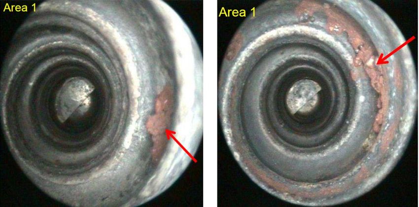
ATSB – AO-2015-107

The occurrence
Preparation for the flight
On 12 September 2015, a Virgin Australia Regional Airlines (VARA) Airbus A320-231, registered
VH-FNP (FNP), was prepared for a charter flight from Perth Airport, Western Australia (WA) to
Boolgeeda Airport, WA. When the captain arrived at the aircraft, he noticed the ground engineer
had the auxiliary power unit running, which was normal, but also had a ground power unit
connected to the aircraft. The engineer informed the captain that this was because the batteries
had gone flat during overnight maintenance to rectify a previous issue with a flight management
and guidance system. 1 Upon entering the cockpit, the captain found it was still untidy from the
overnight maintenance and a number of controls and system configurations were not in their
normal settings.
Confirming that the batteries were charging, the captain continued preparation for the flight. The
first officer joined the captain at the aircraft and they completed the pre-flight preparation without
further issue. The battery charge was completed and the seven cabin crew and 139 passengers
boarded ready for departure.

Take-off and climb
At 0636 Western Standard Time, 2 the aircraft pushed back from the terminal and the flight crew
started the engines, commencing with engine 2. 3 While engine 2 was starting, the flight crew
received two system alerts: ‘park brake on’ and ‘engine 1 shutdown’. The captain discussed this
with the engineer, remarking that it was probably related to the overnight maintenance and the
batteries being low, but would see what happened when engine 1 was started. However, both
alerts appeared to resolve themselves and disappeared before engine 1 start was commenced.
The flight crew reported that it was not unusual to receive short ‘spurious’ alerts during engine
start, so continued with the preparation for departure. At this time, the captain also remarked to
the engineer his concern about possibly getting spurious alerts at a critical time and requested that
they hold for a couple of minutes to make sure there were no more alerts.
While the aircraft was being taxied to the runway, the flight crew performed a flight control check,
which involved moving all controls to their extents to ensure full and correct movement. The flight
crew reported that it is normal system behaviour for the flight control system page to automatically
appear on the system display 4 when the controls are moved for this check; however, on this
occasion the captain had to manually select the flight controls page. The flight crew discussed this
and associating it with the spurious alerts during engine start decided to continue with the flight.
The taxi was continued to the end of runway 21 and at 0650, the flight crew commenced the
take-off from runway 21, with the captain as the pilot flying. 5

1   An integrated system that computes the aircraft’s position using a database of aircraft performance and navigation
    data. It can direct the aircraft along a planned flight profile (ground track, vertical and speed profiles).
2   Western Standard Time (WST): Coordinated Universal Time (UTC) + 8 hours.
3   The engines on the A320 are numbered 1 and 2 from left to right looking forward. That is, engine 1 is on the left wing
    and engine 2 is on the right wing.
4   The system display is a display on the instrument panel dedicated to presenting information about particular systems.
    The system of interest can be displayed either automatically, in the case of a system failure, or manually selected by
    the flight crew. Further information is contained in the section titled Electronic instrument system
5   Pilot flying and pilot monitoring: procedurally assigned roles with specifically assigned duties at specific stages of a
    flight. The pilot flying does most of the flying, except in defined circumstances; such as planning for descent, approach
    and landing. The pilot monitoring carries out support duties and monitors the pilot flying’s actions and the aircraft’s flight
    path.

                                                            ›1‹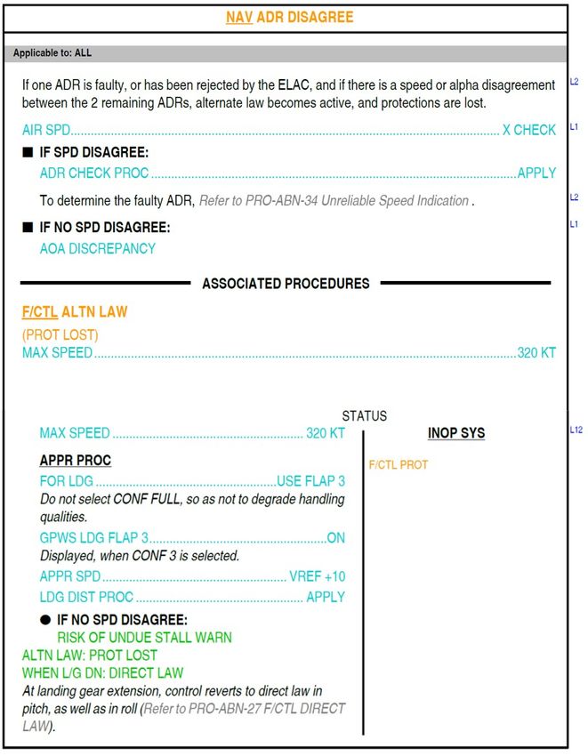
ATSB – AO-2015-107

During the take-off roll, the first officer announced passing 100 kt, which was confirmed verbally by
the captain. 6 The aircraft continued to accelerate; it was rotated and lifted off into a positive climb
away to the south on a standard instrument departure.
After making a turn to the west, with the autopilot and autothrust systems engaged, air traffic
control (ATC) cancelled the standard instrument departure and cleared them to track direct to
Morawa. 7 The flight crew requested, and were cleared, to continue on their current westward
heading so that they could clear some showers that were in the area.
At 0654:39, as the aircraft was climbing through about 8,000 ft above mean sea level, the
autothrust disengaged, generating an alert and locking the thrust at the current setting. Ten
seconds later, the autopilot disengaged (Figure 1).
Figure 1: The flight path taken by VH-FNP when departing from Perth, up to the point that
the autopilot disengaged

Note: The green flight path indicates when the autopilot was engaged, orange when the autopilot was not engaged. North is toward the top of
the image. Source: Google earth, annotated by the ATSB

The flight crew attempted to re-engage the autopilot, but without success. They then identified on
the electronic centralised aircraft monitoring (ECAM) system an alert for engine 1 EPR mode 8 fault
(ENG 1 EPR MODE FAULT). At this point, the ECAM likely presented the following alerts to the
flight crew (Figure 2).

6   According to the analysis carried out by the aircraft manufacturer (refer to the section titled Manufacturer’s analysis), an
    airspeed discrepancy was identified in the stand-by system (CAS 3) during the take-off roll. It could not be determined
    from the recorded information if CAS 3 was erroneous when the 100 kt check was carried out.
7   A navigation waypoint about 300 km to the north of Perth.
8   EPR (engine pressure ratio) mode is the engine’s normal operating mode. In this mode, thrust controlled is based upon
    the ratio of the engine inlet and exhaust pressures. Autothrust requires that EPR mode is available. Further information
    on the engine modes is in the section titled Power plants.

                                                                 ›2‹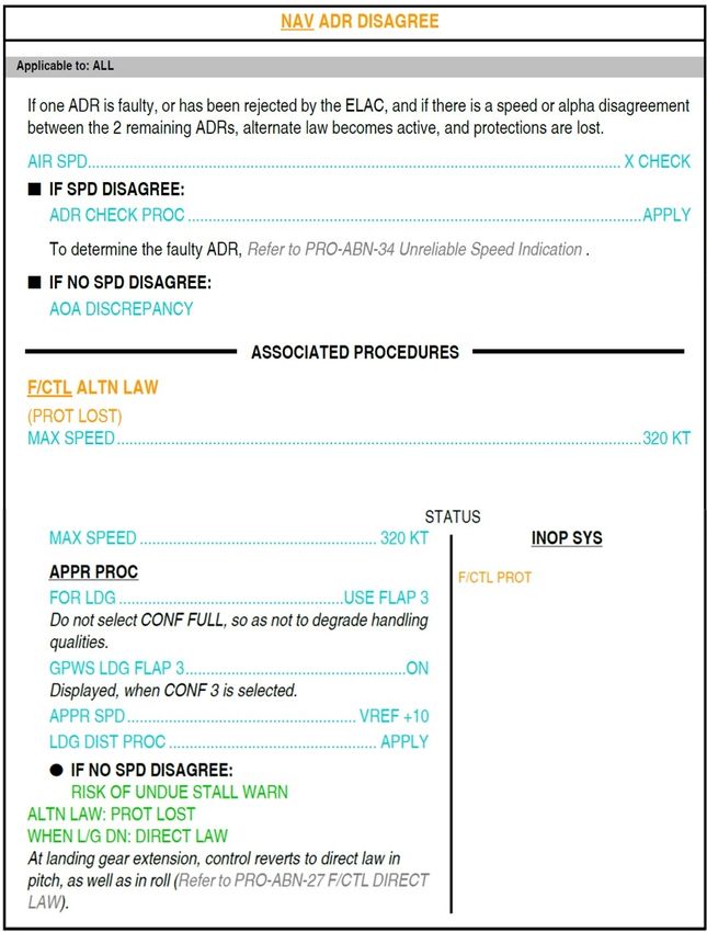
ATSB – AO-2015-107

Figure 2: Representation of the ECAM messages presented to the flight crew when the
autopilot disengaged 9

Source: ATSB

The captain took manual control of the aircraft and continued the climb. At this time, the aircraft
had automatically changed the mode of airspeed control from ‘managed’ to ‘selected’, 10 and
advised the flight crew to set the target airspeed to the green dot speed. 11 However, the green dot
speed was not presented to the flight crew on the airspeed indicator, so the captain elected to fly
the aircraft at a 10° nose-up attitude to ensure that the aircraft continued to climb.
While continuing the climb, the captain turned the aircraft northward toward the cleared track to
Morawa, and asked the first officer to attempt to get some automation back. The captain made
comment to the first officer regarding the airspeed limit and the loss of other speed information.
The speed indicated on the captain’s display at this time was about 290 kt, 40 kt above their
cleared speed of 250 kt.
At 0657:11 (2 minutes and 21 seconds after the autopilot disconnected), while passing through
about 15,700 ft, the flight crew were cleared by ATC to flight level (FL) 12 350. Before
acknowledging this, the captain asked the first officer to commence the actions presented on the
ECAM related to the alerts (referred to as ECAM actions). However, as the first officer
commenced reading from the ECAM, starting with the autoflight (AUTO FLT AP OFF) alert, the
captain interrupted him to confirm the clearance from ATC. The first officer confirmed the cleared
altitude and attempted to continue with the ECAM actions, but the captain decided that he did not
wish to continue to the cleared altitude and asked the first officer to request clearance to FL 200
instead. The request was granted by ATC, who were also informed that they were
troubleshooting.
Before continuing with the ECAM actions, the captain asked the first officer to contact the cabin to
have the cabin crew and passengers remain seated while they deal with some technical issues.
During this period, the captain’s primary concerns were controlling the aircraft on the correct
heading, considering the approach of FL 200, and attempting to get some control of the speed.
The first officer again attempted to commence the ECAM actions, but as they started the ENG 1
EPR MODE FAULT actions, ATC contacted the flight crew, to transfer from Perth Departures to
Melbourne Centre, which required a change in the radio frequency.
At this time, noting that the aircraft was also approaching FL 200, the captain expressed a
concern that the speed would increase as they levelled out so they needed to deal with the

9    This representation is based upon information supplied by Airbus and is prior to the flight crew actioning any of the
     ECAM procedures.
10   The aircraft provides two types of automatic control, managed and selected. In managed mode, the target parameters,
     for example airspeed, are calculated by the flight guidance and management computers to attain the predetermined
     flight path. In selected mode, those targets are selected by the flight crew.
11   A characteristic speed for the aircraft that gives the best lift-to-drag speed for the clean (flaps and landing gear
     retracted) aircraft at the current weight. The green dot speed is presented to the flight crew as a green dot on the
     airspeed indicator. Flying at the green dot speed will achieve the best climb gradient.
12   Flight level: at altitudes above 10,000 ft in Australia, an aircraft’s height above mean sea level is referred to as a flight
     level (FL). FL 350 equates to 35,000 ft

                                                             ›3‹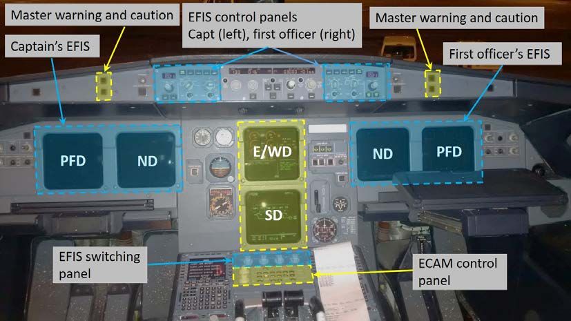
ATSB – AO-2015-107
engines. The captain asked the first officer to continue with the ECAM actions for the engines, and
delay communications with ATC. The ECAM actions for the ENG 1 EPR MODE FAULT involved
switching both engines to N1 mode 13 and manually adjusting the thrust. When this was completed
and the aircraft levelled out, the first officer reminded the captain of ATC’s request for a frequency
change.
The captain noted that the airspeed was coming back down to 250 kt and requested that the first
officer speak to Melbourne Centre and inform them of their situation. During the conversation, the
captain also requested a change in heading to 360° (north), which would be easier to maintain
than a track to a waypoint, when flying manually. The request was approved by ATC.
Troubleshooting and return to Perth
Having organised their ATC clearances, the flight crew then returned their attention to the ECAM
actions. The flight crew had already completed all of the actions for the ENG 1 EPR MODE
FAULT, but none of those actions resulted in a change to the ECAM display, so the first action
taken was to clear that alert. The next message, ENG 2 EPR MODE FAULT required the same
action, which having already been completed required only the alert to be cleared. When this was
done, the first officer announced that the next alert was NAV ADR DISAGREE. At almost 8
minutes 30 seconds since the autopilot had disconnected, this was the first time that the flight
crew had made mention of the NAV ADR DISAGREE (navigation - air data reference disagree)
message.
The specified action for the NAV ADR DISAGREE alert was to crosscheck the airspeeds between
the captain, first officer and standby indicators. As the first officer started actioning the ECAM, the
captain asked him to make a cabin announcement to let the passengers know that they were
having some technical issues and that they would be returning to Perth when they had sorted
them out. While the captain was asking the first officer to do this, the first officer was heard calling
out ‘two-fifty, two-fifty, two-fifty’ [consistent with the airspeed at that time]. The cabin crew were
busy making an announcement, so the first officer was not able to make the cabin announcement,
and the flight crew continued with the ECAM actions. The captain confirmed with the first officer
that there was no disagreement with the airspeeds. Noting that, if there had been an airspeed
discrepancy, the air data reference (ADR) check procedure was required, but because there was
not, he announced that there was an angle of attack 14 discrepancy. 15
The flight crew briefly discussed an angle of attack discrepancy. This appeared to cause some
confusion, with the first officer reading out some figures of 5° and 6° 16 and indicating that there
was no discrepancy. Although the captain had a questioning tone in his voice, they accepted the
ECAM instructions and cleared the message.
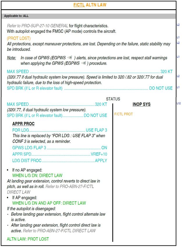
Upon clearing the NAV ADR DISAGREE alert, a F/CTL ALTN LAW (flight control alternate law) 17
alert was presented. Upon receiving this alert, the captain indicated that the issue might have
been more significant than first thought. There were no associated actions for the flight crew to
take, only advisory information that protections were lost and that the airspeed limit was 320 kt, so
the flight crew cleared the alert. This then brought up an AUTO FLT A/THR OFF (auto flight
13 An alternate engine control mode based upon the rotational speed of the engine’s low-pressure system (N1). Further
information on the engine modes is in the section titled Power plants.
14 The relative angle of the wing section to the oncoming airflow.
15 This was in accordance with the procedure for a NAV ADR DISAGREE alert. Refer to section titled Operating
procedures - Abnormal procedures - Navigation – ADR disagree for more information.
16 The angle of attack is not presented on any of the primary displays in the Airbus A320. It can be displayed on the
multipurpose control and display unit in the centre pedestal; however, the first officer reported that these figures were
instinctively read out from the pitch attitude of the aircraft and were not angle of attack values.
17 The digital ‘fly-by-wire’ control system in the Airbus A320 has three control laws; normal, alternate and direct. Further
information on these laws can be found in the Flight control system section of this report.
›4‹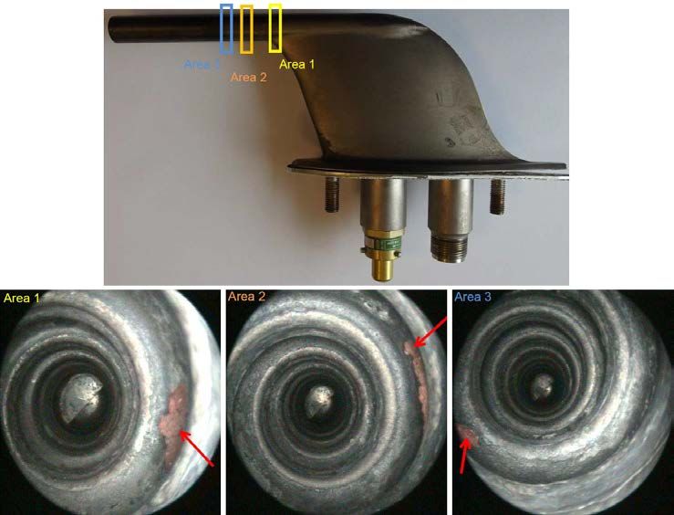
ATSB – AO-2015-107

authothrust off) ECAM alert. 18 Again, there were no actions for the flight crew to attend to, so this
alert was cleared.
The flight crew were then presented with another ECAM alert, this time for AUTO FLT RUD TRV
LIM SYS (autoflight rudder travel limiter system). The ECAM provided advisory information to the
flight crew to use the rudder with care above 160 kt. The first officer then switched off, then back
on, flight augmentation computer number 1 (FAC 1) in accordance with the ECAM procedure.
This resulted in the presentation of two more ECAM alerts. The first, which was likely transitory,
was AUTO FLT RUD TRIM1 FAULT (autoflight rudder trim 1 fault) followed by AUTO FLT RUD
TRV LIM 2 (autoflight rudder travel limiter 2). The second of these ECAM alerts merely noted that
the flight crew be aware of the fault and had no procedure to rectify the fault.
At this point, about 11minutes 30 seconds after the autopilot disconnected, the captain decided to
pause the ECAM actions so that they could assess the situation and deal with other activities. The
captain asked the first officer to check for any tripped circuit breakers, which required the first
officer to leave his seat. No tripped circuit breakers were identified. The captain also took this time
to update the cabin crew, passengers and the company. Meanwhile, they continued northward
away from Perth.
After communicating with the cabin and the company, the flight crew continued their
troubleshooting. This included reviewing the Flight Crew Operating Manual (FCOM) for more
detailed information on ECAM alerts and system faults, and attempting to re-engage the autopilot
(without success).
While reviewing the detailed information in the FCOM, the flight crew reviewed the NAV ADR
DISAGREE procedure, and the associated alternate law procedure. The information in those
procedures advised the flight crew that if there was no speed disagreement, then there was an
angle of attack discrepancy and that there was ‘risk of undue stall warning’. It also advised the
flight crew that the flight controls would revert to direct law when the landing gear was lowered.
At 0720:42, after advising ATC of their intent to return to Perth, the captain again tried to
re-engage the autopilot. The autopilot did not engage, but the captain noticed that he now had a
flight director 19 available. The flight crew discussed the improvement that having this available
made to their workload and decided to try resetting FAC 2. After resetting FAC 2, the flight crew
found that they had the autopilot back.
Having the autopilot back on, the flight crew returned their attention to preparing from the return
and landing. The captain again reviewed the FCOM information highlighting the risk of undue stall
warning.
At 0723:45, when the aircraft was about 245 km north of Perth, the flight crew requested, and
received, a clearance to return the Perth. After making the turn back towards Perth, the flight crew
continued with their preparation for the approach and landing. During their discussions, the
captain indicated that he felt some of the alerts might have been spurious.
Having been advised by ATC that descent into Perth was available; the captain transferred control
to the first officer, and requested and received a clearance to descend to 10,000 ft. The first officer
commenced the descent at 0736, when about 140 km north of Perth.
The flight from take-off to the top of descent, indicating where the key events took place is
presented in Figure 3.

18   The ECAM is designed to prioritise the alerts so that if there are multiple alerts, the alert deemed most important
     appears higher on the list. This message was likely the alert generated when the autothrust disengaged 10 seconds
     before the autopilot disengaged, but the other alerts were assigned a higher priority, pushing this alert off the available
     screen space. Refer to the section titled Electronic instrument system for more information on the ECAM.
19   A function of the autoflight system that provides flight guidance information to the flight crew on their flight displays for
     them to follow with manual control inputs. Accurately following the flight director guidance will have the same result as
     having the autopilot on. Further information on the flight director can be found in the Auto flight section of this report.

                                                             ›5‹
ATSB – AO-2015-107
Figure 3: The flight path from take-off up to top of descent with key points identified
Note: The green flight path indicates when the autopilot was engaged, orange when the autopilot was not engaged. North is toward the left of
the image. Source: Google earth, annotated by the ATSB
Descent and landing
The descent progressed normally; the captain had updated the cabin crew and company on the
situation and they had been cleared by ATC to descend to 5,000 ft. At 0743, as they were passing
through about 10,000 ft, the captain noticed that the airspeed was decreasing and informed the
first officer, who had control. The first officer recalled observing that the minimum speed warning
area on the captain’s airspeed indicator was increasing and announced that there was a
disagreement between the airspeed indicators. At the same time, the captain disconnected the
autopilot and both crew checked the airspeeds on all three indicators. They identified that the
captain’s was indicating lower than the other two, so the captain switched his air data source to
ADR 3. This resulted in the captain’s indicated airspeed increasing to a speed consistent with the
first officer’s indicator. The captain then re-engaged the autopilot and continued with their landing
preparations.
About 3 minutes later, when the flight crew had completed the approach checklist and been
cleared by ATC to descend to 2,500 ft, the autopilot disconnected. At this time, the first officer
stated that his airspeed was indicating 220 kt, with a target of 230 kt. The captain did not verbalise
what speed his was indicating, but the recorded data from the flight indicated that his was about
230 kt. 20
The captain checked the ECAM, cleared the autopilot disconnect warning and noted that the RUD
TRV LIM SYS alert had reappeared. The captain announced that because they had already had
that fault, they would just clear it to get the ECAM status back to what it was.
Noticing that they were probably slightly high on the descent to set up for the approach, the
captain contacted ATC and requested radar vectors 21 to the west, so they could get a few more
track miles before turning back to intercept the localiser. 22 ATC accepted the request and cleared
them to turn to the right and maintain 5,000 ft.
20 The aircraft was fitted with a flight data recorder and cockpit voice recorder. Further information is provided in the
Recorded information section of this report.
21 Radar vectors are tracking directions provided by ATC to assist the flight crew with navigation.
22 The localiser is part of a ground based instrument landing system (ILS) that provides lateral (left-right) guidance to the
flight crew.
›6‹ATSB – AO-2015-107
During an orbit to the west, the captain recapped their situation. Particular note was made that
they were in alternate law, which would transition to direct law when the landing gear was
extended and that [flight envelope] protections were lost. He also reiterated that there was a risk of
undue stall warning.
While heading east, back towards the approach path, the captain contacted ATC to declare a
PAN, 23 notifying them that they had control system issues, were manually flying the aircraft and
were in alternate law. ATC offered the attendance of emergency services for the landing, which
the captain accepted.
After commencing a turn to the right to intercept the localiser, the captain took control from the first
officer. The captain requested that flaps 1 24 be selected and the target speed reduced to 200 kt.
At 0755:02, the aircraft was at an altitude of 2,550 ft and was still in the turn when the stall
warning 25 activated. While the stall warning was active, the captain continued the turn and
repeatedly announced ‘disregard’. After 6 seconds, the stall warning ceased.
After being cleared by ATC for the approach to runway 21, the captain noted that there was a
windshear detection fault. He commented to the first officer that this was to be expected, given the
spurious alerts and requested the associated ECAM alert be cleared. 26
The flight crew continued the approach, and after capturing the glideslope, 27 the captain
requested that flap 3 be selected. The first officer noted that the limit speed for flap 3 was 185 kt.
The captain noted that his airspeed was indicating 175 kt, but the first officer informed him that his
was indicating 190 kt. They continued the approach and the captain requested the target airspeed
be set to 145 kt, about 3 kt higher than the calculated approach speed, to carry a little extra speed
for the approach.
At about 2,400 ft, the landing gear was extended and the approach continued under manual
control. The aircraft touched down at 0800 and the landing was completed without further incident.
The attending emergency services were not required and the flight crew taxied the aircraft back to
the bay.
The descent and approach flight path, with the key events identified, is presented in Figure 4.
23 An internationally recognised radio call announcing an urgency condition, which concerns the safety of an aircraft or its
occupants, but where the flight crew does not require immediate assistance.
24 The first stage of flaps, which at this stage consisted on extension of the leading edge slats only.
25 The stall warning consists of activation of the master warning light and an aural ‘stall’ announcement.
26 The alert was likely a real alert, consistent with the system operation, but misinterpreted by the captain. As described in
the section of the report titled Operating procedures - Windshear detection fault, the fault warning is inhibited until the
flaps are extended, so the captain may not have associated the alert with the factors that led to the fault.
27 The glideslope is part of a ground based instrument landing system that provides vertical (up-down) guidance to the
flight crew.
›7‹ATSB – AO-2015-107
Figure 4: Descent and approach flight path into Perth with key points identified
Note: The green flight path indicates when the autopilot was engaged, orange when the autopilot was not engaged. North is to the left of
the image. Source: Google earth, annotated by the ATSB
›8‹ATSB – AO-2015-107
Context
Meteorological information
The ATSB obtained weather information for Perth from several sources, including the Bureau of
Meteorology (BoM) and the flight crew. The meteorological aerodrome report (METAR) noted the
weather conditions at Perth Airport shortly before pushback at 0630 (Table 1).
Table 1: Perth Airport meteorological conditions at 0630
Wind 5 kt from 260°
Visibility 10 km, or greater
Rain Light rain in showers
28
Cloud Few at 1,200 ft
Scattered at 3,000 ft
Broken at 4,500 ft
29
QNH 1013 HPa
There was also a TEMPO 30 present at the time, which indicated that winds could increase to
gusts of 35 kt, visibility decrease to 3,000 m in showers with moderate rain, with scattered cloud
down to 300 ft and broken cloud down to 800 ft.
The METAR for 0700 showed that there were no significant changes in the weather. The TEMPO
was still active.
The weather radar for Perth showed that there were localised showers moving across the region.
Figure 5 shows the rain showers in the area at 0650, the time that VH-FNP took off from Perth
Airport. The showers were moving from the west towards the east.
28 Cloud cover: in aviation, cloud cover is reported using words that denote the extent of the cover – ‘few’ indicates that up
to a quarter of the sky is covered, ‘scattered’ indicates that cloud is covering between a quarter and a half of the sky,
‘broken’ indicates that more than half to almost all the sky is covered, and ‘overcast’ indicates that all the sky is
covered.
29 The local atmospheric air pressure at mean sea level.
30 Information provided in the weather reports to indicate a temporary deterioration in the forecast weather conditions,
during which significant variation in prevailing conditions are expected to last for periods of between 30 and 60 minutes.
›9‹ATSB – AO-2015-107
Figure 5: Perth weather radar image at 0650 (2250 UTC)
The red arrow indicates the location of Perth Airport and the dashed red rectangle indicates the area presented with the flight path in
Figure 6. Source: Bureau of Meteorology, annotated by the ATSB
The flightpath taken by VH-FNP was superimposed over the region highlighted by the dashed red
rectangle in the radar, as shown above in Figure 5 (Figure 6).
Figure 6: Overlay of flight path on a zoomed in section of the weather radar image taken
at 0650 (2250 UTC), where the region corresponds to the dashed red rectangle in Figure 5
Note: The green flight path indicates when the autopilot was engaged, orange when the autopilot was not engaged. Source: Bureau of
Meteorology, annotated by the ATSB
The captain reported that on the evening before the flight, he had been awoken by heavy rain and
that it was a ‘wintery morning’ when driving to the airport. The METAR confirmed that there had
been 11.4 mm of rain since 0900, on the previous day.
› 10 ‹ATSB – AO-2015-107
The BoM climate summary for September 2015 showed that Perth Airport received rain on 1, 5, 6,
11, and 12 September 2015. The incident day (12 September) being the wettest day of the month.
No rain was recorded at weather stations near Boolgeeda in September 2015.
ATSB observation
The flight crew reported that the aircraft was in instrument meteorological conditions
(IMC) 31 during the climb, and about 10 seconds before the autothrust disconnected, the
cockpit voice recorder (CVR) captured the flight crew discussing showers when delaying
their turn to the north. Given the flight crew’s reports and the proximity of the flight path to
the rain on the weather radar, it was likely that VH-FNP passed through, or along the edges
of, a rain cell before the autothrust and autopilot disconnected.
Aircraft information
VH-FNP is an Airbus A320-231 twin-turbine engine low-wing commercial transport aircraft,
manufactured in France in 1993.
Skywest Airlines first registered the aircraft in Australia in April 2010 before Virgin Australia
Regional Airlines (VARA) purchased Skywest Airlines. Skywest and VARA had primarily operated
VH-FNP on charter flights from Perth to remote mining operations in Western Australia; however,
more recently had increased its use on regular public transport operations. The occurrence flight
was a mining charter flight that was part on an established ongoing contract.
Electronic instrument system
The A320’s electronic instrument system (EIS) presents data to the flight crew regarding the
aircraft and its environment. It consists of the electronic flight instrument system (EFIS) and
electronic centralised aircraft monitoring (ECAM) system (Figure 7, EFIS component highlighted in
blue and ECAM components highlighted in yellow). The EFIS displays mostly flight parameters
and navigation data on the primary flight displays (PFDs) and navigation displays (NDs). The
ECAM presents data on the engine and warning display (E/WD) and system display (SD). Control
and switching panels for the EFIS and ECAM are located on the glareshield and centre console.
Master warning and caution lights are located on the glareshield to draw the flight crew’s attention
to important messages on the ECAM.
31 Weather conditions that require pilots to fly primarily by reference to instruments, rather than by outside visual
reference. Typically, this means flying in cloud or limited visibility.
› 11 ‹ATSB – AO-2015-107
Figure 7: Location of the EIS components in the A320 cockpit
Source: ATSB
The PFD presents flight environment information, such as airspeed, attitude and altitude, and
some navigation information, such as heading and instrument landing system, to the flight crew. It
also includes some flight mode information, such as autopilot and autothrust status (Figure 8).
Figure 8: Primary flight display – information zones (left) and presentation (right)
The
presentation is an example only and does not contain information from the event flight.
Source: Airbus (left) and ATSB (right)
The ECAM is an integrated system that presents data monitored by the aircraft on the engine and
warning display and system display pages in the centre of the instrument panel. The displays are
divided into dedicated areas to display the following information as shown in Figure 9.
• primary engine indications, fuel quantity, flap and slat position
• warning and caution alerts, or memos
• synoptic diagrams of aircraft systems and status messages
• pertinent flight data (air temperature and gross weight).
› 12 ‹ATSB – AO-2015-107
Figure 9: ECAM displays – engine/warning display (upper) and system display (lower)
Source: ATSB
The lower part of the E/WD is dedicated to ECAM warning and caution messages. The left section
presents the specific warning messages and the right section lists the affected systems,
secondary failures, memos or special notices (such as ’LAND ASAP’). When the flight warning
computer (FWC) detects a failure, and if there is no flight phase inhibition active, the title of the
warning is displayed followed by the associated procedures (actions and information).
The ECAM message area is limited in size and can display a maximum of seven lines. If there are
too many messages, or the procedure extends beyond the bottom of the display, a green
‘overflow’ arrow appears at the bottom of the message area, as shown in Figure 2. The flight crew
can scroll down to view the additional messages.
Airbus divides each flight into 10 distinct phases (Figure 10). To prevent distracting the flight crew
during high-workload phases, and to prevent unnecessary warnings, the FWC inhibits some
warnings from being presented on the ECAM during particular phases.
Figure 10: Airbus flight phases
Source: Airbus and ATSB
The ECAM display uses a colour code to indicate the importance of the failure or the indication,
providing the flight crew with an immediate indication of the urgency to take remedial actions
(Table 2).
› 13 ‹ATSB – AO-2015-107
Table 2: ECAM colour coding
Colour Importance
Red The configuration or failure requires immediate action.
Amber The flight crew should be aware of the configuration or failure, but need not take
immediate action.
Green The item is operating normally.
White Provides guidance while various procedures are executed.
Blue Actions to be carried out, or limitations.
Magenta Message applies to particular pieces of equipment or situations.
ECAM alerts (warnings and cautions) are further divided into three levels, indicating its
importance, with level 1 being the lowest and level 3 being the most critical. Depending upon the
level, the message is presented on the ECAM as either a red warning, or amber caution, with an
associated aural alert and illumination of a master warning or caution light on the instrument panel
glareshield (Table 3).
Table 3: ECAM alert level descriptions
Level Description Aural alert Visual alert
3 Red warning: Continuous - Flashing red
Immediate action required, due to: repetitive chime, ‘Master Warning’
specific sound or light.
- aircraft is in a dangerous synthetic voice
configuration, or limit flight - Red warning
message on E/WD.
condition (for example, stall)
- system failure altering the flight - Automatic call of
the relevant system
safety (for example, engine
page on the SD.
fire).
2 Amber caution: Single chime - Steady amber
‘Master Caution’
The flight crew should be aware of
light.
the configuration or failure, but does
not need to take immediate action. - Amber caution
However, it was intended that time message on E/WD.
and situation permitting; these - Automatic call of
cautions should be considered the relevant system
without delay to prevent any further
page on the SD.
degradation of the affected system.
These are for system failures
without any direct consequence on
the flight safety (For example, green
hydraulic system pressure low).
1 Amber caution: None - Amber caution
message on E/WD.
Requires crew monitoring.
Generally without
These are for system failures procedure.
leading to a loss of redundancy or
system degradation.
› 14 ‹ATSB – AO-2015-107
When there are multiple ECAM messages, the order in which they are presented is dictated by the
alert level. Level 3 has priority over level 2, which has priority over level 1. For alerts of the same
level, Airbus has assigned a priority based upon factors decided during design. Airbus advised the
ATSB that for A320 aircraft, amber alerts for engine-related failures have a higher priority than
amber alerts for navigation and air data failures.
The ECAM’s system display (SD) can display 12 system pages, including engine, bleed air,
electrical, hydraulic, and flight control systems. The flight crew, using the ECAM control panel,
may manually select each page, or the system may automatically display a page. System pages
are automatically displayed when a system failure triggers a caution or warning message, or to
advise the flight crew that a relevant parameter has drifted outside of its normal range. If there are
no overriding system page priorities, particular pages are also automatically displayed as the flight
phase’s default page. For example, the ENGINE page will be displayed for phases 3, 4, and 5
(take-off phases).
Additionally, during phase 2, when the WHEEL page is the default page, moving either sidestick
by more than 3° in pitch or roll, or when the rudder pedal is deflected by more than 22°, the
system page will automatically change to the flight control (F/CTL) page. This will only occur
during phase 2, as it is associated with a control check.
Park brake
The A320 park brake applies hydraulic pressure to the aircraft brakes. This can be applied at any
time, but should only be used on the ground. To prevent the aircraft from landing with the park
brake on, the aircraft’s flight warning computer will generate a level 2 amber PARK BRAKE ON
alert when the park brake is on during flight. The system inhibits the warning for flight phases 1 to
5 and 8 to 10, all ground phases, so should only activate when the aircraft is airborne.
Auto flight
The aircraft’s auto flight system is centred on the flight management and guidance system
(FMGS) and consists of two flight management and guidance computers, and two flight
augmentation computers (FAC). The flight management part of the system controls: navigation
and navigation radios, flight planning, performance prediction and optimisation, and display
management. The flight guidance part provides autopilot, flight director and autothrust functions.
Flight crew interact with the system through two multipurpose control and display units in the
centre pedestal and a flight control unit (FCU) in the centre glareshield. The FCU allows the flight
crew to select and modify any flight parameters for short-term operation in selected guidance
mode. The FCU also includes the autopilot and autothrust engagement controls.
The FMGS provides guidance information to either the flight director, or the autopilot. When the
flight director is engaged, flight path guidance information is presented to the flight crew on the
PFD. The flight crew then make control inputs to follow the flight path. When the autopilot is
engaged, it will automatically make control inputs to guide the aircraft along the flight profile. The
autopilot only controls the aerodynamic surface for the aircraft (elevator, aileron and rudder).
Automatic engine thrust is provided by the autothrust function.
The FACs provide yaw damping and roll coordination functions through control of the rudder.
Autopilot
The aircraft has two autopilots, AP1 and AP2, which can be engaged by pressing the
corresponding button on the FCU. The autopilot is disengaged by either the:
• flight crew take an action on the flight control systems, such as pressing the takeover
pushbutton on the sidestick (standard method), pushing the FCU autopilot button when
engaged, or moving the sidestick control
• engagement conditions are no longer met.
› 15 ‹ATSB – AO-2015-107
Detection of certain faults by the aircraft systems can result in the autopilot engagement
conditions not being met, disengaging the autopilot.
Autopilot disengagement produces a level 3 alert, with a flashing red master warning light, red
AUTO FLT AP OFF message on the ECAM, and an aural ‘cavalry charge’ alert.
Autothrust
The autothrust function connects the FMGS to the engine control system so that it can command
the required thrust from the engines. When engaged, the autothrust function can provide a fixed
thrust control, or airspeed control. Autothrust can operate independently, or with the autopilot.
Both the autopilot and autothrust systems can control the target airspeed, but both cannot be
controlling at the same time. In managed climb and descent modes, the autothrust will hold the
engine thrust, and the autopilot will control the airspeed.
The autothrust function requires at least one flight management and guidance computer, one FAC
and two air data inertial reference systems to be operative. It will disconnect when the flight crew
takes a particular action, such as pressing the instinctive disconnect button on the thrust levers
(standard method), or pressing the A/THR button on the FCU, or automatically when the arming
conditions are not met.
Autothrust disconnection produces a level 2 alert, with a master caution light, single chime and an
amber AUTO FLT A/THR OFF message on the ECAM.
When the autothrust is disconnected and the thrust levers are in the climb detent, the thrust lock
function will activate. Thrust lock will lock the thrust at its level prior to the disconnection and
display a flashing amber message on the flight mode annunciator in the PFD. Thrust lock is
disabled by moving the thrust levers out of the climb detent.
Power plants
VH-FNP was fitted with two International Aero Engines V2500 high-bypass turbofan engines. The
engine is of a twin-shaft design, consisting of low-pressure (LP) and high-pressure (HP) systems
on separate shafts (Figure 11). The low-pressure system consists of the fan, low-pressure
compressor and turbine. Similarly, the high-pressure system consists of a high-pressure
compressor and turbine.
Figure 11: V2500 engine schematic diagram
Source: VARA Flight Crew Operating Manual. Additional annotation by ATSB
In normal operation, the engine thrust setting is achieved through control of the engine pressure
ratio (EPR). 32 This normal mode of operation is referred to as EPR mode. To operate in EPR
mode, the engine control system requires valid pressure and temperature data (P2, P5 and T2).
32 The ratio of the LP turbine exhaust pressure (P5) to the engine intake pressure (P2).
› 16 ‹ATSB – AO-2015-107
To ensure the integrity of this data, the engine monitors the total air pressure measured by the
aircraft’s air data reference (ADR) system. If the engine control system determines that either P2
or P5 are not valid, or cannot verify them against the aircraft supplied ADR data, thrust control will
automatically revert to N1 mode. This will result in a level 2 amber ENG 1(2) EPR MODE FAULT
alert on the ECAM.
In N1 mode, the rotational speed of the low-pressure system (N1) is controlled. N1 mode has two
sub-modes, rated N1 mode and degraded N1 mode. Reversion to rated N1 mode occurs when
either P2 and/or P5 are invalid, and reversion to degraded N1 mode occurs when T2 or the
ambient pressure parameters are not valid. Autothrust is not available when in N1 mode.
When in EPR mode, rated N1 mode can be manually selected through the ENG N1 MODE push-
button switches on the overhead panel. After an automatic reversion to rated N1 mode, pressing
the button confirms the mode.
In the case where the engine core speed drops below the idle speed, with the master switch on,
the ECAM will present a level 2 amber ENG 1(2) FAIL alert. However, this warning is inhibited
during flight phases 1 and 10 (engine start and after engine shutdown).
Air data reference system
The air data reference (ADR) system 33 senses air temperature, static and total air pressure, and
angle of attack information. It then converts them to useable data, such as computed airspeed and
altitude, for supply to other aircraft systems, including the FMGS, flight warning computers, flight
control system, and engine control system.
The ADR system consists of three independent systems: one for the captain (ADR 1), one for the
first officer (ADR 2) and a standby system (ADR 3). Air data is collected from the external airflow
via 14 external probes and ports mounted on the forward fuselage (Figure 12).
Figure 12: Air data reference system external probe locations
Source: Airbus
Sensors connected to these probes convert the external air conditions to electronic signals, which
are then sent to the three air data inertial reference units (ADIRUs) (Figure 13). The ADIRUs then
convert these signals to useable system data. The standby system also supplies static and total
(pitot) air pressure to direct reading analogue airspeed and altitude indicators on the instrument
panel.
33 The air data reference system is part of the air data inertial reference system (ADIRS), the other part being the inertial
reference system. This report is only concerned with the air data reference system.
› 17 ‹ATSB – AO-2015-107
Figure 13: Air data reference system schematic
ADM = air data module (the sensor that converts air pressure to an electric signal) Source: Airbus
In the normal configuration, the captain’s PFD presents information from ADIRU 1, the first
officer’s from ADIRU 2. However, in case of an ADIRU 1 or 2 failure, ADIRU 3 data can be
directed to either the captain’s or first officer’s PFD, as required, using the EFIS switching in the
centre pedestal (Figure 7 and Figure 14).
Figure 14: EFIS switching panel. Air data source switch highlighted by yellow box
Source: ATSB
All of the external probes and ports are heated to prevent the accumulation of ice, which could
degrade their accuracy. The captain’s, first officer’s and standby systems are controlled and
monitored by three independent probe heat computers.
The probes are automatically heated when at least one engine is running, or when the aircraft is in
flight. They can also be manually operated through a pushbutton in the cockpit. When on the
ground, the pitot and total air temperature probes operate at a low level and automatically change
to normal power when airborne.
If a fault is detected in any of the ADR systems, a level 2 alert is raised, activating the master
caution and presenting an amber NAV ADR 1(2)(3) FAULT message on the ECAM. A FAULT
› 18 ‹ATSB – AO-2015-107
light on the applicable ADR pushbutton switch on the overhead panel is also illuminated to
indicate which system is affected.
If one ADR has been detected as being faulty, or has been rejected by the flight control
computers, and there is an airspeed or angle of attack disagreement between the remaining two
ADRs, then a level 2 alert is raised. This activates the master caution and presents an amber NAV
ADR DISAGREE message on the ECAM.
Pitot probe details
The pitot probes collect the total air pressure, which is a combination of the static (ambient) air
pressure and the pressure increase due to moving air being brought to a standstill. The difference
between the measured total and static air pressure is the component due to the velocity alone,
and as such is used to calculate the airspeed.
The pitot probe is a tube with a forward facing opening mounted on the side of the fuselage
(Figure 15). To ensure it has clean air, the opening of the probe is held away from the fuselage.
To prevent water from blocking the probe, two small drain holes are drilled into the lower side of
the probe.
Figure 15: Pitot probe
Source: ATSB
Flight control system
General
The Airbus A320 has a digital fly-by-wire control system. Manual control inputs made by the pilots
on the sidesticks, or autopilot computer commands, are interpreted by the flight control computers
and converted to control surface movements. Seven flight control computers, including the two
FACs, control the aircraft’s elevators for pitch control, ailerons and spoilers for roll control, and
rudder for yaw control. Signals from these computers are sent directly to the associated control
surfaces and to the EIS for presentation of pertinent information.
To prevent damage to the vertical stabiliser, the FACs include a rudder travel limit function. This
function reduces the maximum rudder travel deflection at high airspeeds. In the case of a loss of
the rudder travel limit system in the clean configuration, 34 the rudder deflection limit is held at the
last value. When the slats are extended, the FACs automatically set the rudder deflection limit at
the low-speed setting (maximum authorised deflection).
If one FAC is unable to provide rudder travel limit function, a level 1 alert is activated. The master
caution is not activated, but an amber RUD TRV LIM 1(2) message is presented on the ECAM. If
both FACs are unable to provide the rudder travel limit function, a level 2 alert is activated. This
activates the master caution and presents an amber RUD TRV LIM SYS message on the ECAM.
34 Flaps and landing gear retracted.
› 19 ‹ATSB – AO-2015-107
Control laws
The A320 flight control system operates according to three sets of control laws:
• normal law
• alternate law
• direct law.
As the name suggests, normal law is the control law used in normal operation. Under normal
law, 35 sidestick inputs command a load factor, which the flight control computers convert to the
appropriate elevator deflections. Normal law includes the following flight envelope protections:
• load factor limitation
• pitch attitude protection
• high angle of attack protection, limiting the angle of attack, preventing the aircraft from stalling
• high speed protection
• bank angle protection.
The FACs calculate a speed corresponding to the limit angle of attack, which presented to the
flight crew on the airspeed indicators as a minimum speed warning area. The FACs also calculate
the minimum and maximum limit speeds, manoeuvring speeds and speed trend. These speeds
are included in a set of speeds referred to as ‘characteristic speeds’ presented to the flight crew
on their PFDs.
To function in normal law, the flight control computers require valid air data from the ADRs. The
computers monitor all three ADR systems to assess the validity of the air data parameters. If the
value of a parameter from one ADR differs from the others, the flight control system will discard
the non-consistent value and use the other two. 36 However, if all values are different the system
cannot determine the correct value and cannot ensure the functions of normal law. In this case,
the system will reconfigure the control laws to alternate law, depending on the data it can
validate. 37 Reversion to direct law will occur at landing gear extension.
When in alternate law, the control laws are predominantly the same as normal law, but the level of
flight envelope protection is reduced. The flight control system has two levels of alternate law, with
or without reduced protections.
• Alternate law with reduced protections - provides load factor limitation, low-speed stability, and
high-speed stability. There are no pitch or roll attitude protections and the high angle of attack
protections are replaced with a stall warning.
• Alternate law without reduced protections - loses all flight envelope protections, except for load
factor limitation. High angle of attack protection is replaced by a stall warning. 38
For both levels of alternate law, a calculated stall warning speed is presented on the PFD
airspeed indicator, replacing the high angle of attack protection speeds.
The type of failure, or the nature of the particular system that failed, dictates which alternate law is
used. For example, when the system detects a computed airspeed disagreement, the system
reconfigures to alternate law without reduced protections. However, when an angle of attack
disagreement is detected, the system will reconfigure to alternate law with reduced protections.
35 The description provided is applicable to normal law in flight mode. Normal law includes a number of other modes, such
as flare mode, where the control laws differ from those described. However, for the purposes of this report, only the
flight mode is described.
36 Some of the flight control computers will latch a discarded air data parameter out (that is discontinue using that
parameter) until the computer has been reset, even if the parameter returns to being consistent with the other
parameters.
37 Other system failures may also result in the flight computers reconfiguring to alternate or direct laws.
38 The stall warning includes a synthetic voice ‘STALL’ message produced over the audio system and cockpit speaker.
› 20 ‹You can also read