Supercharged Four Wheel Drive Ford Mondeo ST220
←
→
Page content transcription
If your browser does not render page correctly, please read the page content below
Supercharged Four Wheel Drive Ford Mondeo ST220
                                     Jon Marchant

I should have written this as an open project log from day one but alas I couldn’t be
bothered at the time and never thought it would go this far.
So, here we are in October 2009…

Project goals

More power and torque
Aiming for 350Bhp. Have read of an intercooled Procharger supercharged ST220 on
one of the ST owners club forums that was alleged to develop 321Bhp at the flywheel
with only 6 Psi boost pressure.
So this became the bench-mark. Additional fuelling on this car achieved with a
booster fuel pump and a ‘digital FMU’ which is essentially a manifold pressure
sensing fuel pump controller – the FMU increases the speed of the in-line booster fuel
pump according to measured boost pressure thereby increasing the fuel rail pressure,
causing the injectors to deliver more fuel. Sounds simple, although very crude.

Long-term plan, four wheel drive conversion
Theoretically possible as in 1994/1995 a 4x4 version of the Mk1 Mondeo was
produced in limited numbers with the 2 litre Zetec-E engine. The drive train layout,
fuel tank and rear axle assembly ‘should’ be compatible as the floor pan remained
essentially unchanged in the Mk2 and Mk3 models.
A 4x4 version of the Jaguar X-type 3 litre sport also exists with an engine derived
from the Ford Duratec 30 and with a bodyshell and running gear developed from that
used in the Mk3 Mondeo.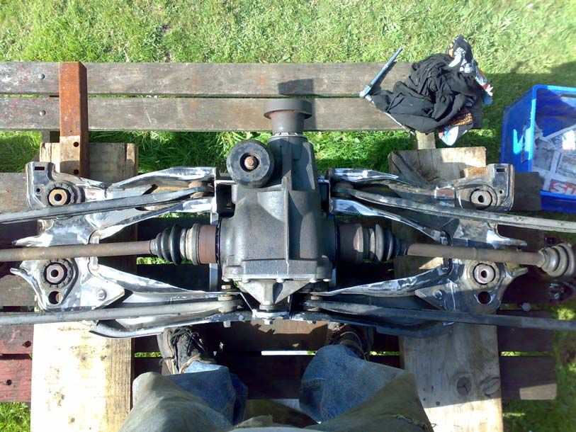
Start date: April 2008

Initial Modifications:

   •   Eibach lowering springs, 25mm drop, later settled to approx 40mm total drop,
       improved appearance of car, slightly harder ride, slightly sharper turn-in and
       more feedback through steering. Not good over speed bumps and have to be
       careful reversing as exhausts are now low enough to hit a tall curb.

   •   Miltek cat-back exhaust system, improvement on the standard exhaust system
       in terms of gas flow and exhaust note, deeper and slightly louder. Improved
       low-mid range torque noticeably and increased fuel economy by around 1-
       2mpg!

   •   Focus ST front brakes, much sharper and less susceptible to fade compared to
       the poor standard Mondeo brakes. Front brakes are a straight swap but the rear
       calipers are not. Previously tried EBC grooved discs and ‘red stuff’ ceramic
       pads, the pads were good, little warm-up required and no fade but the discs
       were crap. The grooved discs made a strange whirring noise from the pads
       dragging over the grooves even when not braking. This was only noticeable at
       low speed with the windows down but still louder than the exhaust. Discs also
       ‘warped’ within 6 months. Standard Focus ST discs and pads ok so far.

More Power!!!

Having already carried out some investigation into forced induction tuning the
ST220’s Duratec 30 V6 engine the following was considered (bearing in mind that my
knowledge has developed with the project so at this point I was still very ‘green’):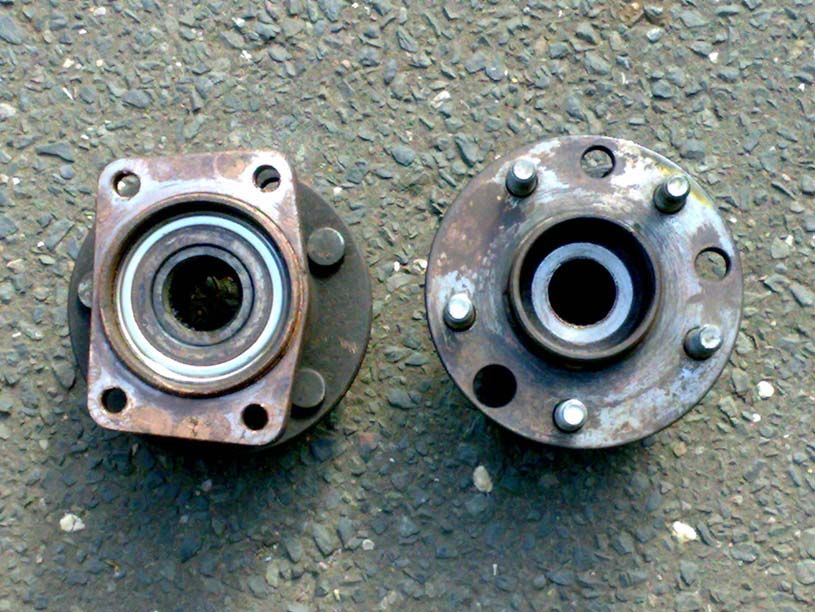
Turbocharging

Favoured for overall efficiency and outright power as well as the potential for a lot of
mid-range torque if the turbo/engine combination is well matched. Good for the
‘shove’ factor due to the torque, making the car ‘feel’ faster.
Ideal would be a twin turbo set-up with turbochargers sized small enough to minimise
lag but the total output of the two enough for good top end power. Discounted due to
lack of space in engine bay, as well as the complexity and cost.

Then considered a larger single hybrid turbo such as a T04E, this should just fit in the
space in front of the gearbox but would necessitate relocation of the battery to the
boot and some ‘interesting’ exhaust and induction pipe-work.
This seemed like a good idea and indeed there is a company called Nautilus
Performance in the US who manufacture a kit for the Ford Contour (Mk2 Mondeo)
2.5 V6, a good starting point for ideas, but…

Further investigation suggested that to achieve 350+ Bhp would require 10+ Psi of
boost pressure and lowering of the static compression ratio from the standard 10.0:1
to something more like 8.5:1 as well as forged pistons and forged connecting rods –
not a cost I thought could be justified at the time.
On top of that there would likely be significant lag due to using a larger-ish turbo
resulting in a sharp increase in torque when the turbo starts to develop useful boost,
this would certainly provide the desired ‘shove’ but at the expense of low speed
driveability and shock loading of the clutch, gearbox and suspension.
Then there is heat management to consider, the turbocharger as well as its associated
exhaust pipe-work will be running very hot and any adjacent components will need
adequate heat shielding in an already cramped engine bay.

Turbocharging was starting to appear less attractive or at least less practical in this
application.
Supercharging

Positive displacement superchargers were considered due to the good low-speed
torque characteristic but then quickly ruled out due to lack of space.
Any supercharger by design has to be driven by the engine and the only useable
power take off is from the auxiliary drive belt, which limits the locating options for
superchargers considerably. PD superchargers are physically relatively large and as
the ST220 has a rather cramped engine bay there is no space available to the front or
rear of the engine so the supercharger would have to fit on top in the conventional
position.
But again there is little space available, not unless a large power bulge is incorporated
in the bonnet.

Next on the list was centrifugal superchargers like the one used in the bench mark
supercharged ST220.
Centrifugal superchargers use a centrifugal compressor of the same type as
turbochargers, the main difference being that they are not driven by an exhaust driven
turbine but by the engine through a step-up gearbox from the auxiliary drive belt.

Centrifugal superchargers share turbochargers’ high adiabatic efficiency meaning that
they generate less heating of the charge air during compression when compared to a
positive displacement supercharger. In addition to this they do not heat the charge air
by heat soak from a hot, close-coupled exhaust turbine like turbochargers do.
This potentially means overall the charge air will be cooler and have a higher density
than with a turbo set-up at the same boost pressure so more power can be developed
with less boost pressure.
Centrifugal superchargers are also relatively more compact than PD superchargers.
Unfortunately like a turbo, centrifugal superchargers also need to be running at high
speed to produce any useful boost pressure, which is why centrifugal superchargers all
use some form of step-up drive to increase the speed of the engine to something more
useful at the compressor wheel.
This in itself is not a problem but in addition all fixed drive superchargers are engine
speed dependant and there is a limit to how fast the supercharger can be driven.
Therefore at low speed there is little or no boost available but increases steadily up to
the engine rev limit.

Typically a centrifugal supercharger that is set up to develop 8 Psi boost at an engine
speed of 7000 Rpm will only develop 2-3 Psi at 3000 Rpm, a bit like having a large
turbo with lots of lag then a very smooth on-boost transition.
Technically this is very desirable as the load on the clutch, gearbox and suspension is
minimised, there is much less chance of wheel spin and torque steer and the engine
sees highest boost pressure when it is most able to handle it – at high speed.
Probably not as much fun though…

In theory a centrifugal supercharger coupled with some form of variable drive would
be the best solution. The variable drive would have a higher step-up ratio at low
engine speed to give the required boost pressure then progressively decrease with
increasing engine speed to maintain the boost pressure at much the same level without
leading to over-boost or over-speeding the supercharger.
Paxton Superchargers in the US did this back in the 50s/60s using variable pulley v-
belt drives and variable ball drives. At this time I believe there is a company
developing multi ratio planetary drives for use with Rotrex centrifugal superchargers.
Variable pulley drives were again ruled out due to lack of space around the auxiliary
drive belt area but still like the idea.
Another possibility is hydraulic drive. Whereby a hydraulic pump is driven from the
auxiliary belt which in turn drives a hydraulic motor, coupled to the input shaft of a
centrifugal supercharger. If the flow rate of the pump is higher than that required by
the motor for a given rotational speed then a step-up drive relationship can exist, this
could then be varied electronically using a proportional control valve to control the
hydraulic fluid flow rate and bypass the excess.
I liked this idea a lot because it potentially means more low-speed boost pressure and
proportional electronic control is possible, it also frees the supercharger from the
constraints of having to be located where it can be driven by the auxiliary drive belt as
the only connection to the pump would be hoses.
Also the only component needing to be driven by the auxiliary belt would be a
relatively small hydraulic pump, which should be fairly easy to accommodate.

I pursued this idea with Parker Hydraulics, specifically their hydraulic fan drive
systems for some time but was eventually told their motors were not capable of
running as fast as first suggested. Then I started having doubts that the benefits would
outweigh the cost and complexity, not that complexity is necessarily something to be
scared of.

So, it was decided to just go along with the conventional set-up for the time being.
The conventional set-up for centrifugal superchargers is fixed ratio belt drive.
The required engine airflow and boost pressure for the desired power output is
calculated, then that point looked up on the supercharger compressor map, the
required impeller speed is then read-off.
This is the target speed for the supercharger’s compressor wheel when the engine
speed hits the desired shift point or otherwise at the engine rev-limit.
Working backwards the required drive pulley sizes can be calculated.
For my target 350 bhp, the boost pressure required would be around 8 psi.

This calculation alone does not take into account the effect of adding an intercooler
into the system, which can be very significant as I later found out to my cost.
Suitable centrifugal superchargers:
• Rotrex, European manufactured, very compact, neat design and much smaller
than other comparable centrifugal superchargers but also significantly more
expensive.
• Paxton, US manufactured, internal synchronous belt step-up drive, lower step-
up ratio than other comparable units.
• Procharger, US manufactured, fairly common, second-hand units occasionally
appear.
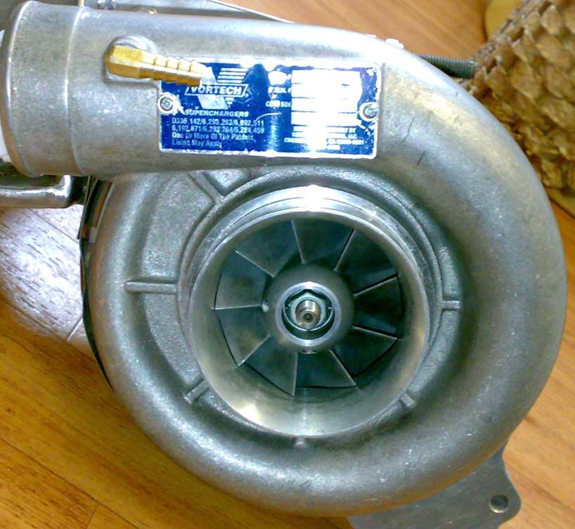
• Vortech, US manufactured, as with the Procharger units, fairly common and
second-hand units occasionally appear.
All the US manufactured units seemed to be similar in specification and size but when
I came across a suitable second hand Vortech V9F supercharger in need of a re-build,
the choice was made for me.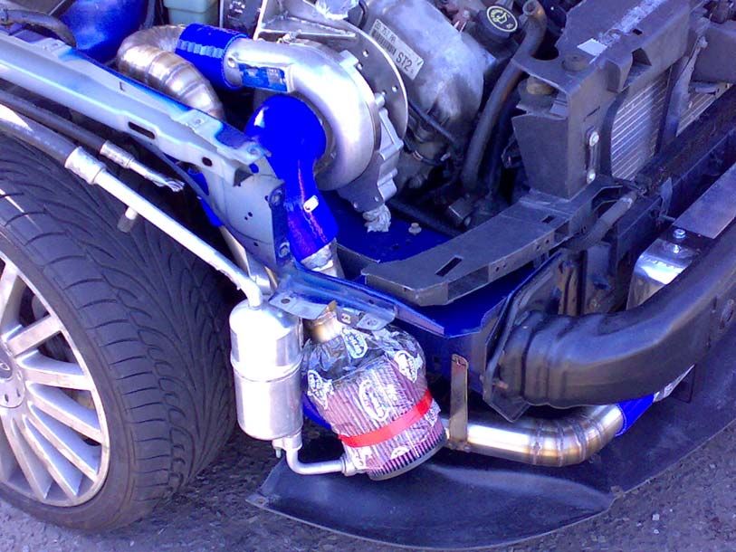
Fuel and Ignition

There is also the issue of ECU recalibration. Simple, piggy-back controllers such as
the digital FMU were discounted at this point as further research highlighted just how
far from ideal these systems are and more importantly that they are not fail-safe.
A failure of such a system will result in no additional fuel being supplied under boost
causing a lean condition, leading to detonation and potentially serious engine damage.

So recalibration or ‘re-mapping’ of the OEM ECU is the way to go for accurate
correction of fuelling and ignition. Fitting an after-market ECU was considered for all
of 5 minutes until I realised how insanely expensive most are, also the OEM ECU
controls not just the engine but also other functions such as the ESP and AC, which I
did not want to lose.

So I set about locating and contacting tuning companies in the South East who could
carry out the necessary re-calibration.
Not wanting to slate the industry I did make a few observations. A lot of tuning
companies do not carry out any actual tuning, fitting aftermarket exhausts, induction
kits, stereos etc. are the kind of thing you should be able to do yourself competently if
you drive a ‘tweeked’ motor and do not really constitute ‘tuning’.
There also seem to be quite a few tuning companies that only deal with diesels and/or
will re-program your car’s ECU with a pre-programmed map from a hand held
programmer developed by a proper tuning company.

With a little more research I came across Dreamscience who were marketing a re-
packaged version of the SCT - XCAL3 with a pre-programmed map they had
developed for the standard and mildly modified ST220 and provision for custom re-
mapping.
I contacted Dreamscience regarding custom re-mapping of my ST220 with a
supercharger fitted and they referred me to one of their master dealers who had
experience with custom mapping forced induction modified Fords and a good
reputation.

The company in question is Performance 3000 in Yeovil, Somerset. When contacted
they were helpful, and indicated that they would be able to carry out the required re-
mapping and provided a quote.
Fitting the Supercharger
With a company located who could carry out the ECU re-mapping, work was
underway to fit the already rebuilt supercharger.
Another plug: Kent Bearings, St leonards-on-sea, East Sussex. Very helpful sourcing
suitable replacement high-speed bearings and seals for the supercharger. There were
some re-build kits available on Ebay for my supercharger, one of which was actually
included with the unit I bought but was a completely unsuitable. The high speed
bearings were just bearings that happened to be the correct size but were not rated for
high speed use at all and would have quickly overheated and seized!
Most of the research into suitable supercharger location took place before purchasing
the unit but it was very difficult to be sure without actually offering the supercharger
in the engine bay to see where it would fit.
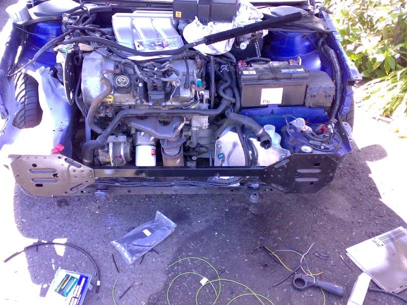
The standard ST220 engine bay before modification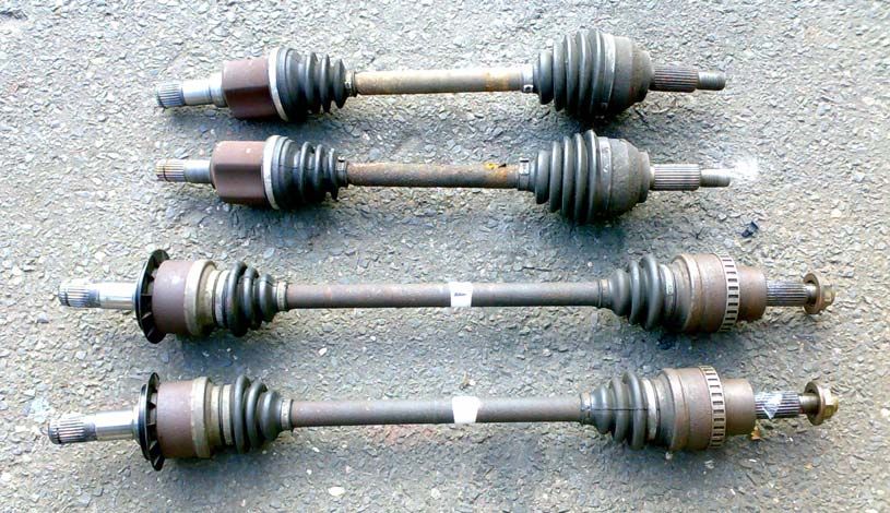
And a close-up of the area around the auxiliary drive belt
In the late 1990s Vortech offered a supercharger kit with one of their V9 units for the
Ford Contour V6, the US version of the Mk2 Mondeo 2.5 V6.
This kit located the supercharger to the gearbox end of the engine towards the front
and used a shaft to take drive for the supercharger from the auxiliary drive belt and
across the front of the engine to the supercharger.
This worked, but not for long…
They encountered several serious failures of the drive shaft assembly and withdrew
the kit from sale. A redesigned kit was later marketed but was very short-lived and I
could not find one.

I did look into copying the layout of the Vortech kit but with more research it began to
look impractical as the Mk3 engine bay is different to that of the Mk2 and the
Contour. This arrangement also necessitated relocation of the battery to the boot as
with the turbo kits. For some reason I had a real problem with the idea of relocating
the battery at the time, although have since moved just about everything else.

I then came across another company in the US who were developing a supercharger
kit for the Contour using a Vortech V9 (3lduratec.com).
At the time they were not offering any kits for sale but had successfully developed
some prototype vehicles.
Looking at the pictures of their prototypes, it looked as though the supercharger
would also fit in this location in my ST220 with a little modification.

3lduratec.com Ford Contour supercharger location

The supercharger is fitted to a very tidy looking bracket, which in turn is fixed to the
studs on the top of the upper engine mount bracket.
A neat idea but it does look like the bracket would flex under load as no bracing can
be seen in the picture, the routing of the belt drive is also not too obvious.
After looking at the above picture for a while it seemed fairly obvious to make the
supercharger bracket part of the upper engine mount.
In the end I came up with what is shown below.

Note some of the following pictures were taken during build and others after (the ones
I forgot), so are not necessarily in chronological order.

Bracket fabricated from stainless steel plate

The induction system progressed from here on a ‘wherever it’ll fit’ basis
Combined MAF and IAT (air mass flow and charge air temperature) sensor retained
in original position

Bypass valve assembly, the blue one is a dump valve for relieving boost pressure
when transitioning off-throttle, which prevents compressor stall and reduces load on
the bearings.
The purple valve is a modified version of the same dump valve and is configured for
pressure relief to limit maximum boost pressure (if required).
Bypass valves in position

Bypass valves re-circulate air back to supercharger inlet
The screen washer tank and pumps had to be relocated from in front of the driver’s
side front wheel to in front of the gearbox.

The coolant header tank also had to be relocated

Some of the AC hoses also had to be moved and modified to accommodate the
supercharger intake duct. There are very few people who want to help with any sort of
modification to vehicle AC systems, lesson learned, en evil to be avoided if possible
which unfortunately it wasn’t in this case.
Supercharger power take-off pulley – 2 power steering pump pulleys modified to fit
back to back. I did consider the additional radial load on the power steering pump
bearing, but as the belts will be pulling away in nearly opposite directions, thought
this would semi-cancel.

Custom supercharger drive pulley with one-way sprag clutches fitted to allow
supercharger to wind down gently during off-throttle transition rather than be forced
to slow by drive belt. Reduces reverse-load on belt drive, which is designed to
transmit power in one direction only. Incidentally the alternator is fitted with a sprag
clutch pulley as standard.
A spring loaded dynamic belt tensioner could not be accommodated due to lack of
space so had to opt for an adjustable lever tensioner arrangement.

View showing belt run around pulleys.
In addition to the modifications shown above a higher flow fuel pump was fitted
along with higher flow injectors to cater for the increased fuel requirements of the
supercharged engine.
The high flow fuel pump was purchased from PumaSpeed, advertised as a Focus RS
(MK1) up-rated fuel pump good for 500 Bhp, this lasted 2 weeks and failed while
driving through town on my way home from work. The pump had failed open circuit
for apparently no reason so was returned for warranty replacement.

I can’t remember the size of the standard injectors, think they were something like
24 lb/hr @ 3bar, the replacement injectors are Ford racing ‘Blue Giant’ (Bosch 0280
156 127) 39 lb/hr @ 3bar which have been flow tested to 42 lb/hr @ 3bar (441
cc/min).
These will flow 52 lb/hr (543 cc/min) at the ST220’s fuel rail pressure of 4.5 bar and
be good for well over 400 Bhp.

Due to changing the injectors the ECU’s basic calibration is now incorrect and as a
result injects way too much fuel so the engine will not start or run any sense and is
now un-driveable at this stage.
Re-mapping: September 2008

After much work the car was ready to be re-mapped and after pulling a few favours
the car was towed down to Yeovil.
About half way through the second day of mapping I’m informed that the
supercharger is not producing nearly as much boost as expected, struggling to reach 4
Psi, let alone the desired 8 Psi, but as I needed to be able to drive the car back home,
suggested that the mapping continue.

Meanwhile I re-did all the calculations and could not find anything wrong, the only
factor not accounted for was the flow restriction caused by the intercooler. The
intercooler was sized so that the end-on flow area of the core was just over double the
area of the incoming and exiting pipes and pressure loss was not expected to be more
than 1 Psi max.

I was then informed that the MAF sensor had maxed out or ‘pegged’ at around 5000
rpm and above this point the engine was starting to run lean. The standard MAF
sensor was too sensitive and hit its maximum output voltage at 5000 rpm, well before
the rev limiter at 6900 rpm.
The only solution was a larger flow MAF sensor and as I also had to find out why the
supercharger was not producing the expected boost pressure, the car was mapped to
run safe with the rev limiter reduced to 5500 rpm so I could drive it home,
disappointed.

When home I looked at the numbers trying to understand how I’d got it so
catastrophically wrong.
Maxing out the MAF sensor was always going to be a risk but was surprised it
happened so low in the rev band with so little boost pressure. Producing such low
boost pressure was not expected though.
Everything seemed correct so I fitted 2 boost pressure gauges, one at the supercharger
discharge and another to the inlet manifold and went for a drive.
The supercharger was producing the expected boost pressure but this was not reaching
the inlet manifold. Was it the intercooler, the throttle body, the convoluted bends in
my pipework?

I took the intercooler out and replaced it with a straight section of tube and went for
another drive: zero pressure loss, it was all down to the intercooler, the engine was
now also much more responsive as well and generally felt much nicer to drive.
However above 6 Psi boost pressure it is generally recommended that an intercooler is
used to keep the charge air temperature down or limit boost pressure, so an intercooler
had to be fitted.
.
The intercooler used was a relatively cheap universal fit one sourced from Ebay. It
looked good enough though, high-flow bar and plate construction, decent size,
rounded end tanks, although the inlet and outlet hose connections were a little
restrictive.
The end tanks and hose connections were single piece castings welded onto each end
of the core. The hose connection O/D was 2.25”, the rest of the pressurised part of the
induction system is 2.5”, but the I/D was only around 2.0”.
To improve this the hose connections were cut off and some larger I/D connections
welded on and the intercooler re-fitted.
This did make a significant improvement - it had now gone from a 45% pressure drop
to around 30%.

A larger MAF sensor also had to be sourced and fitted and I’d also been advised to
relocate the MAF to the supercharger intake side so that air is being drawn through
rather than forced through under pressure. This is supposed to result in greater
accuracy and reliability as some MAFs do not like operating under pressure.
After some research a new 90mm MAF as fitted to a Ford F150 Lightning was
sourced again through Ebay.

These are larger than the standard ST220 MAF (90mm as opposed to 75mm), pin for
pin compatible except for the omission of the integral IAT sensor and designed for
much higher airflow as they are normally fitted to a 5.4 litre supercharged V8!

Relocating the MAF upstream of the supercharger did also entail fitting of a separate
charge air temperature (IAT) sensor in the original MAF sensor location so that the
actual charge air temperature is measured from the air entering the inlet manifold after
compression and intercooling. The standard ST220 MAF sensor has its own integral
IAT sensor.
A Ford Explorer IAT sensor was sourced for this purpose as they are cheap from Ford
and testing revealed have the same temperature/resistance relationship as the IAT
thermistor integral to the standard ST220 MAF.
89mm (3.5”) diameter supercharger intake

As for getting the boost pressure back up to the level desired, I attempted to calculate
how much the supercharger discharge pressure would have to be increased to obtain
the desired 8 Psi at the inlet manifold but struggled as the pressure drop across the
intercooler did not appear to be fixed.

It was decided to simply alter the supercharger pulley size so that the supercharger
would run up to its maximum allowable speed and let the boost pressure limiting
valve do its job as required – I had originally been advised against trying this but was
now willing to take the risk as it seemed likely there would be little excess pressure
(airflow) to re-circulate.
I had also now been advised that the engine could probably run up to 10 Psi boost
without problems due to the low charge air temperature.

The max operating speed for the Vortech V9 supercharger was quoted at 62,000 rpm
impeller speed by the manufacturer but later de-rated to 55,000 rpm.
I opted for a supercharger speed of 56,000 rpm at an engine speed of 6900 rpm as this
is the long-term limit of the high-speed bearings used during re-building the
supercharger and so another custom pulley was manufactured.
Re-mapping: April 2009

Ready for another try, the rev limit was lowered to 5000 rpm using the XCAL 3 ‘user
adjustable options’ the boost limiter valve set to full relief by removing the spring and
to be on the safe side, the tank filled with premium 98 RON for the trip down to
Yeovil.
On arrival at Performance 3000 the spring was re-fitted to the limiter valve and the
new MAF and IAT sensors plugged in (the original MAF sensor had to be used for
the drive down).
Then mapping commenced.

The initial set-up went well and the car was soon running correctly with the new MAF
and IAT sensors, the new MAF had a lot more headroom than the original and the
supercharger was producing significantly more boost pressure at lower engine speed.
Mapping then progressed and was looking good until half way through the second day
when problems were encountered at around 5000 rpm under load. It seemed almost
like the onset of detonation but could not be remedied by retarding ignition timing or
increasing fuelling to reduce burn temperature.
The charge air temperature was also very low, far lower than would normally be
required to contribute to the onset of detonation.

Turned out that the engine was misfiring. I forget the name used to describe it but the
spark plugs were breaking down and arcing through the side of the ceramic insulators
into the HT lead caps. My understanding is that the insulating effect of the fuel/air
charge in the cylinders under pressure at high engine load increases the breakdown
voltage of the spark plug gap to a point where the plug if weak, can breakdown
elsewhere, in this case through the side of the insulators and into the HT lead caps and
presumably then into the cylinder head which is the nearest ground.
This was evidenced by small black pin marks around the spark plug insulators
towards the top. The plugs and leads could not hack it but conveniently I had a new
set of standard leads in to boot so new plugs were ordered in for the next morning and
once fitted this cured the problem.

Mapping continued but then it seemed that the boost pressure was topping out at
around 6 psi and would not rise further. The limiter valve was wound fully shut, this
improved but did not solve the problem so the dump valve was also wound fully shut
and boost pressure continued to rise.
This then caused another problem though as it was found that the supercharger shifts
enough air at idle that with the throttle shut the pressure rises enough for the
compressor to stall causing rapid cyclic airflow reversal back through the
supercharger and into the MAF sensor, the output of which was looking rather like a
triangle wave.
This totally screwed up the mapping at idle and was un-resolvable through further
calibration/mapping.
The solution was to rip out the original diaphragm dump valve and fit a decent Bailey
piston dump valve.
Mapping once again resumed but the engine still seemed to be struggling to get
enough air approaching 6000 rpm. Removal of the air filter was tried but settled for
simply removing the pre-charger screen from the cone filter as this noticeably
increased the airflow but still not enough.
The pressure differential across the intercooler was observed to be quite high so a
much larger intercooler dug out of the stock room and trial fitted.
This instantly freed up another 20 bhp and oddly did not hurt the throttle response as
expected.

At this point the car was now developing 300 bhp at the wheels at 6100 rpm and
assuming approx 17-20% transmission loss is already meeting my target with another
900 rpm or so to go, but then as mapping continued another problem arose.

Power output good at 6100 rpm then suddenly falls off very sharply with MAF, IAT
and boost pressure remaining constant.
Some head scratching ensued but collectively decided that the exhaust system most
notably the catalytic converters is limiting gas flow out of the engine and likely
causing a sharp increase in exhaust back-pressure and exhaust gas temperature (EGT)
above 6100 rpm.

So, back home for some more work. During the drive home it was discovered that the
rev limiter was for some reason not functioning, an issue that has still yet to be
resolved.

Below is one of the later dyno print-outs, this one cut short at 5972 rpm but already
showing a power output of 292 bhp measured at the front wheels.
Further Development

Back home the new larger intercooler and dump valve were properly installed. The
boost pressure limiting valve was also removed and replaced with a proper external
wastegate as used in high power turbocharger installations.
The wastegate has a much larger diaphragm and spring than the weak modified dump
valve and so much more capable of holding the boost back without creeping open.

The wastegate, like the pressure relief valve, is fitted only as insurance against the
remote possibility that the supercharger does eventually produce more boost pressure
than desired. The wastegate will most likely not be required and if so, will be removed
after further re-mapping.

                           With larger intercooler fitted
New dump (bypass) valve fitted
Wastegate valveThe Engine After some discussion it was decided to try source some forged pistons and connecting rods as the engine was already making good power and is not yet done. Nobody seems to be able to advise just how much the standard ST220 engine bottom end can handle, but everybody agrees that the standard sintered rods are a liability. It is expected that freeing up the exhaust system should allow the engine to develop significantly more power beyond 6000 rpm. Normally with centrifugal supercharger set-ups the engine power output rises steadily all the way up to the limiter as there is usually no drop off in supercharger output unless it is too small for the engine’s airflow requirements. Reference back to the compressor map for the V9F supercharger indicates there is plenty more airflow available so the supercharger should not be a limiting factor here. Research revealed that although forged K1 Carillo rods are available for the Duratec 30 engine, the only forged pistons available are low compression ratio 8.5:1 perfect for higher boost pressure applications such as high output turbocharging. This rather made me wish I’d gone with the turbocharging route in the first place as this is a major cost I had not banked on with supercharging. As this is a relatively low boost pressure application, the static compression ratio can be kept reasonably high and did not want to lose low down torque and power throughout the rev range by lowering the compression. To maintain the standard compression ratio of 10.0:1 the only option is custom forged pistons at even higher cost. Custom forged Wiseco pistons and forged Carillo rods ordered from Flatlander Performance 20/08/2009 on a 6 week lead-time.
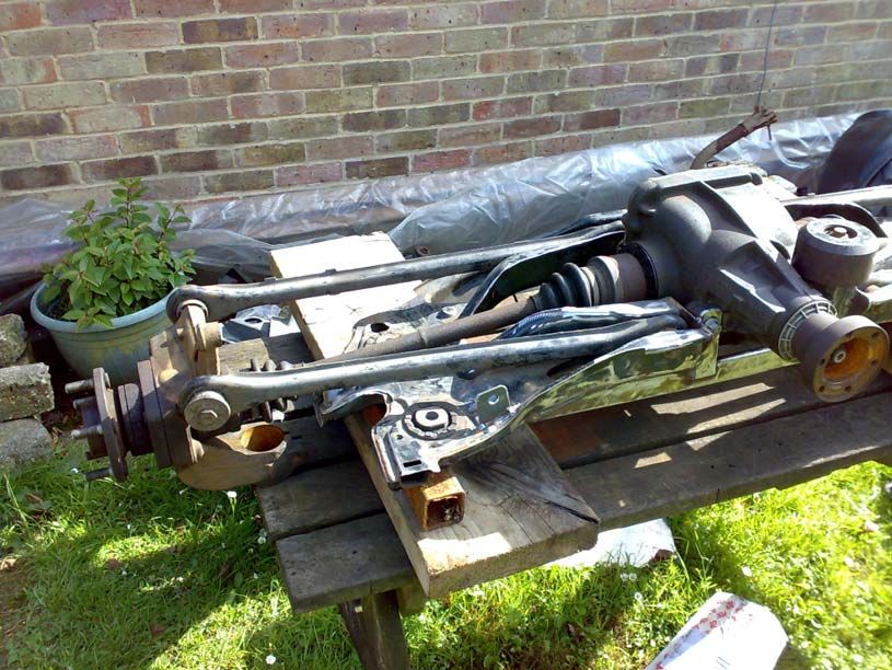
Four Wheel Drive

While waiting for the pistons and rods to arrive, work on the exhaust system could
take place but it seemed sensible to first make some headway with the rear axle and
fuel tank part of the 4x4 conversion so the modified exhaust system could be routed in
sympathy rather than re-routing it again later.
The major components of the 4x4 system from a low mileage Jaguar X-Type 3.0 sport
had been purchased at the right price and sitting idle for some time. The parts
included the gearbox, transfer box, front driveshafts, propshaft and the rear sub-frame
complete with all running gear.
A fuel tank from a 1995 Mondeo Si 4x4 was also sourced at a later date.
Fuel System

The first job was to fit the 4x4 fuel tank. The 4x4 tank is of the ‘saddle’ design where
the normal large single fuel tank is effectively split into 2 separate tanks by a
transmission tunnel and has a large bridge running over the top. This necessitates the
use of 2 fuel pick-ups. The fuel pump and fuel level sender reside in much the same
position as for the standard tanks except there is now an additional pick-up and sender
assembly on the other side.
Fuel is siphoned over from the second pick-up by a valve and t-piece fitted in the
main fuel pump return line.

By this time the replacement fuel pump from PumaSpeed had already failed in the
same manner as before!!!?
After some discussion with PumaSpeed the pump was returned for credit, which I did
receive after 3 months of chasing!

So, another fuel pump was needed and the only standard size high-flow pump I could
find that would fit in the new fuel tank (or indeed the original tank) was a Walbro
GS342 high pressure 255 litre/hour pump.
By my calculations I need up to 195 l/hr @ 4.5 bar but the Walbro pump will not
deliver this flow at such a high pressure. An additional pump was needed. Following
advice from Performance 3000 I looked into the Bosch 044 inline fuel pumps. These
will flow 300 l/hr at up to 5 bar.
I now have the Walbro 255 l/hr high-pressure pump in the tank as a lift pump and the
Bosch 044 pump along with an adjustable pressure regulator and fuel filter mounted
inside the rear of the boot.
I still have reservations about the location of the Bosch pump due to noise in the
cabin, something yet to be resolved.
The Mk1 Mondeo 4x4 saddle tank thankfully fitted straight where the original tank sat
but the rear mounting points for the retaining straps had to be moved further apart as
one strap actually ran through the tunnel.
I ended up welding lugs onto the rear subframe for this purpose and also lengthening
the straps.
The Mk1 filler neck also had to be used as the ST220 filler will not fit the Mk1 tank.

The in-tank pump/sender assembly with the Walbro pump fitted

The transfer pick-up/sender assembly
The main fuel pump, pressure regulator and filter inside the boot

The evaporative emissions charcoal canister also had to be relocated behind the trim
inside the boot due to lack of space around the rear axle where it originally resided.
Mk3 Mondeo (ST220) OEM ‘return-less’ fuel system

                              To fuel rail

                                    Filter

              Fill

                                    Pump       Reg
           Fuel tank
                                                       Pump/sender
                                                       assembly

MK1 Mondeo 4x4 saddle tank OEM fuel system

       To fuel rail and regulator

     Feed                   Return

    Fill                      Siphon valve included within pump/sender 1 assembly

                                Siphon valve         Tank

              Pump

                                    Tunnel

      Pump and sender 1                                 Pick-up and sender 2
Modified 4x4 saddle tank high flow/pressure fuel system
To fuel rail
Filter
Regulator
Swirl pot Main
pump
Fill Siphon valve included within pump/sender 1 assembly
Siphon valve Tank
Pump
Tunnel
Pump and sender 1 Pick-up and sender 2
Standard 4x4 fuel system modified with addition of:
• Walbro 255 l/hr high pressure pump as lift pump
• Swirl pot to reduce chance of main pump drawing any air
• Bosch 044 high flow, high pressure main pump
• Adjustable external fuel pressure regulatorSimplified 4x4 saddle tank fuel system without swirl pot
To fuel rail
Filter
Regulator
Main
pump
Fill Siphon valve included within pump/sender 1 assembly
Siphon valve Tank
Pump
Tunnel
Balance
Pump and sender 1 Pick-up and sender 2
line
Swirl pot removed as found to be serving no useful purpose.
When the lift pump draws air it appears to ‘airate’ the fuel in the swirl pot so the main
pump draws fuel with air bubbles in and cavitates causing a drop in fuel pressure and
the pump to run hot.
Balance line added connecting bottom of both sided of tank to allow fuel levels to
equalize under gravity.4x4 Saddle tank fuel system with pumped crossover (triple pump system)
To fuel rail
Filter
Regulator
Main
pump
Fill
Tank
Pump
Tunnel Pump
Pump and sender 1 Pump and sender 2
Balance line does not work very effectively and proved difficult to accommodate
around exhaust and quite vulnerable so removed.
Siphon transfer also does not seem to work all that well so opted for a pumped
transfer using and standard fuel pump and sender assembly in place of the existing
transfer pick-up and sender assembly.At free-flow the transfer pump ‘should’ pump fuel over as fast as the lift pump can pump it out. There ‘should’ always be fuel returning to this side of the tank so the transfer pump ‘should’ not run dry. Yet to be proven… Subject to flow testing, the noisy gerotor-type Walbro 255 l/hr lift pump may be removed in favour of the standard ST220 turbine-type pump, which is near silent. It is believed at free-flow this pump should be able to deliver sufficient fuel to the Bosch pressure pump.
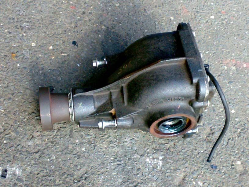
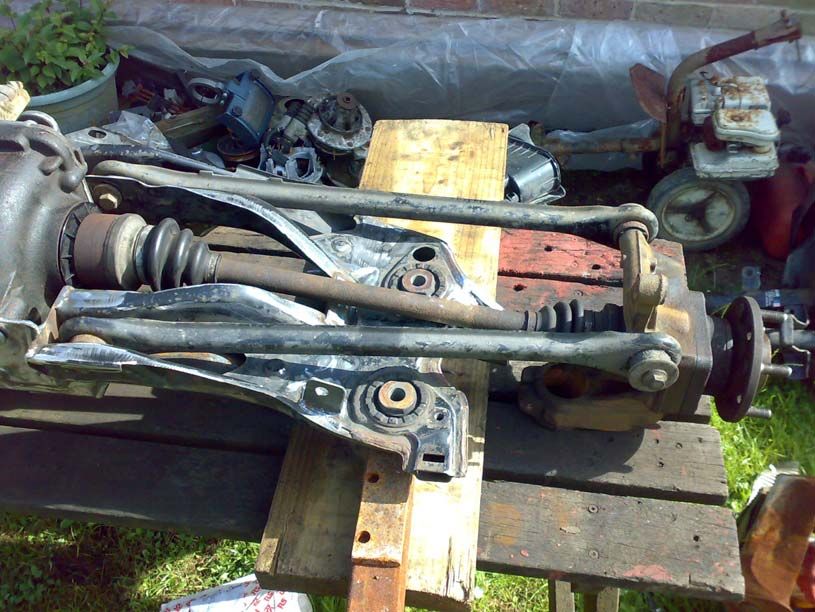
Rear Axle

Then work began on the rear axle.
The Jaguar X-Type rear sub-frame and suspension is based on the Mondeo estate rear
as this better accommodated the drive components and increases boot space (for golf
clubs) as the springs are under the car much like the Focus ‘control blade’ set-up.
This negated the use of the Jaguar rear sub-frame as the rear of the car is totally
different and it would definitely not fit without serious modification to the rear of the
bodyshell.
I looked into the Mondeo Si 4x4 rear axle but these are very rare and most have seen
high mileage service. While the sub-frame looked like it could be a straight swap-in
fit, the differential is much smaller the than the Jaguar unit already purchased so
wondered if the existing ST220 rear sub-frame could be modified to accept the Jag
diff.

After swapping a few parts around to see what would fit, it appeared that as suspected
the Jag and Mondeo rear track was almost exactly the same width and the rear hubs
were interchangeable. There were a few obvious issues like the different rear
ABS/ESP wheel sensors and the anti-roll bar ends being in the way but nothing un-
resolvable.
The ST220 rear sub-frame was removed and the Jaguar differential and driveshafts
offered up to see if it could all be made to fit.
This turned out to be a lot easier than first thought but think there will be ongoing
issues with clearance between the underside of the sub-frame and the outer ends of the
rear driveshafts in the areas circled below.
This fabrication work was carried out on a proper flat metal workbench in a suitable
workshop – not on the picnic bench on which the frame is pictured.
During modification of the subframe, additional strengthening was welded in to
replace the material removed and overall geometry maintained.
The rear subframe once modified was sent away for Zinc flame spraying and painting,
then assembled onto the car.
The anti-roll bar links had to be replaced with shorter items to shift the ends of the bar
just above the outer CV joints.

With the rear suspension all fitted the driveshaft clearance was checked with 2 people
sitting on the back seat, the resulting 40mm clearance may just be enough allowing
for bumps and the usual poor road surface.
The rear suspension strut bump stops were later extended by approx 25mm with
sections of the bump stops from the Jaguar subframe.
This was done after it was found that the driveshafts did contact the subframe when
driving over potholes (every couple of feet) so the ride height will need to be
addressed.
The original Mondeo ST220 rear wheel sensors were integral to the rear hub
assemblies so the Jaguar sensors had to be used instead.
Disassembly of one of the Mondeo rear hub assemblies revealed that both the Mondeo
and Jaguar wheel sensor tone rings although of different construction, have 32
interruptions (pulses) per revolution, so the ABS/ESP should function OK –
thankfully it does.
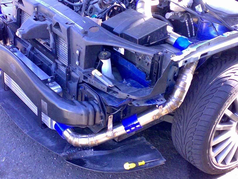
The exhaust system

The standard exhaust system consisted of front and rear bank exhaust manifolds each
feeding straight into its own catalytic converter.
The cats both exited into 2” diameter pipes which ran rearwards to the bulkhead
where they fed through 2 flexi joints and into the first box, 2 pipes in and 2 out. Both
pipes then fed into the next box, again 2 pipes in and 2 out.
Leaving the second box both pipes joined from 2 x 2” into a single 2.5” pipe, which
ran around the fuel tank then split once more into 2 x 2” pipes and then into each rear
muffler.
The Miltek exhaust system that had already been fitted took the output from both flexi
joints into a single 2.5” pipe all the way back with no centre boxes before splitting
into 2 x 2” pipes then into the straight-through rear mufflers.

The catalytic converters needed to be removed with provision for fitting a single cat
back in for the MOT and enlarging at least the forward section of the exhaust system
to increase flow where possible.
Due to the proposed future fitting of 4 wheel drive a single pipe had to be used from
the front to rear to make way for the propshaft.
The result is 2 x 2.5” down pipes from the manifolds both joining into a single 3.0”
pipe at the bulkhead.

Note the incorporation of a flexi section and sleeve coupling in the forward down pipe
to aid fitting and accommodate some expansion related movement. A large flexi is
also fitted after the y-connection to accommodate engine movement (torque reaction)
as per the original system design requirements for a transverse engine.
An M18x1.5 boss was also fitted after the y-connection for a wideband lambda probe.
After the main flexi-joint there is a 14” long removable section with V-band flanges
for easy removal. This is where a cat can be swapped in for MOT.

This work was taking place at the same time as additional work for the 4x4
conversion so the mid-rear section of the exhaust system was modified to run through
the transmission tunnel in the fuel tank and around the rear differential.
The rear section including mufflers was reused in modified form from the aftermarket
Miltek system.
Looking rearwards from under the engine, the route of the exhaust system as well as
the space for the propshaft can be seen.

At this stage the gearbox, transfer box and propshaft cannot be fitted to complete the
4x4 conversion due to the fact that Performance 3000 only have a 2 wheel drive
rolling road dynomometer and the ECU requires further calibration/mapping work.
When the gearbox is changed it is proposed to take the opportunity to replace the
clutch with a higher torque capacity item.

There have been some reliability issues reported concerning the Jaguar transfer box
which is assumed to be down to the use of lifetime oil and only 0.6 litres at that. It is
proposed to fit an oil circulation pump and cooler to the gearbox and transfer box,
probably using the main gearbox casing as the reservoir.

Having previously purchased a transfer box as spares or repair, they do appear to be
fairly solid except for the centre differential viscous coupling, which in this case was
cooked. The apparent lack of oil was also noted, instead just greasy scum inside the
casing.
Current state of engine bay: October 2009
Next:

   •    Fit forged pistons and rods when they arrive, including new head gaskets,
        bolts and big end bearing shells (bearing source: Modus Engineering).
   •    Fit shorter supercharger drive belt and correctly tension.
   •    Develop fuel level sender interface/correction unit.
   •    Attempt live datalogging with XCAL 3, and wideband O2 and MAP sensors
        connected to analogue inputs.
   •    Sort out the handling – crap new tyres? Already tried 4 wheel alignment,
        removing the rear diff and refitting the original rear hubs and fitting old part
        worn tyres to rear. All made noticeable improvements but high-speed
        (squirming) instability still exists.
Update November 2009 Flow testing of standard Visteon ST220 fuel pump indicates that it will not meet the peak demand of the main pump so cannot be used in place of the Walbro unit. Instead the Visteon pump is fitted as the transfer pump – at least one pump is quiet. Have also had to make a small interface unit to allow the fuel gauge to operate using the two tank sender units. This includes a comparator circuit that shuts of the transfer pump when the fuel level drops too low on that side of the tank. Lift pump assembly with siphon valve removed Transfer pump assembly using standard ST220 fuel pump
Fuel pump controller – under rear seat

    Relays for in-tank fuel pumps
Note to self – tidy this up and make an access cover
Update Early December 2009

Forged pistons and rods arrived and workshop space organised to carry out work.
All necessary gaskets, bolts, studs etc. sourced from Ford.
Disassembly – this is what a stripped ST220 Duratec 30 looks like
Original pistons and rods as removed

New pistons and rods almost ready for fitting – the ring gap has to be checked by
placing the rings in to bores prior to fitting to pistons.
Undersize ring gaps enlarged with a ring grinder (or an oil stone)
Then things started to go less well…

These are the big end shells of #6, no evidence of wear and look pretty good

These are the big end shells of #1 showing heavy scoring due to some form of
abrasive contamination in the oil.
All except #6 are affected, although #1 is the worst.

No sign of debris in oil so likely occurred before last oil change, however this could
not be ignored.
The oil is drawn from the sump, through the pick-up and strainer, which appeared to
be clean and into the oil pump.
The oil pump was removed and disassembled for inspection revealing significant
scoring of the rotors and housing – probably still fit for use but not happy so not going
to take the risk.
The oil pump then pumps the oil through the oil filter which evidently failed to do its’
job, and into the main oil gallery.
Incidentally, have only ever used new, genuine Ford oil filters and good quality fully
synthetic oil, very frustrating!

The oil then passes from the main gallery up into the cylinder heads to lubricate the
camshafts and supply oil to the hydraulic adjusters (and also from here to the
supercharger).
Thankfully no evidence of damage or contamination was found in the heads or
supercharger, if so the project would have ceased here due to the cost of repair.
The oil also passes from the main gallery to the crankshaft main bearings and through
drillings in the crankshaft to the big end bearings where the damage was first noticed.
This means that the contamination first had to pass through the mains before reaching
the big ends.

This presents a dilemma as Ford will only supply a complete short engine, no parts for
the bottom end are available.

Some internet research and a few phone calls later a few options were presented.
Managed to find a new Ford Maverick 3.0 V6 oil pump on Ebay (same basic engine).
The main bearing shells are available through engine builders (had already had to
purchase big-end shells for the piston and rod upgrade, Federal Mogul part number –
7262M (standard size).
The crankshaft oil seals are available through Ford under part numbers: F5AZ-6700,
F5AZ-6701 (these are Ford USA part numbers).
The main bearing cap bolts are torque-to-yield and will also need to be replaced,
available from Jaguar (3.0 V6 X-Type, S-Type), part numbers: XR83302 (8 off),
XR85191 (4 off), XR85193 (5 off), possibly also available from Mazda.
Alternatively ARP now supply a main stud kit for the Duratec 25 and 30 engines
under part number: 253-5402.

Decided to dive in and remove the remainder of the engine from the car and strip the
crank out.
Turns out this may have been a good move as although the main shells were in
reasonable condition, one had very deep scoring present.
Luckily the crank seemed more or less ok so simply polished the journals with crocus
paper and left it at that.

The necessary parts were sourced and proceeded with the rebuild although having just
added around £400 extra to the parts cost, really feeling the pinch now…

Incidentally the piston pins are not an interference fit in the pistons as indicated by the
information I’d read and are simply retained by round wire clips as per the
aftermarket pistons – or at least that’s the case with my engine. It is therefore feasible
to easily replace the rods only and reuse the standard pistons and rings.
The disassembled block and heads were flushed out and steam cleaned before
rebuilding – didn’t want any more contamination.
Rebuilt bottom end with new bearings, pistons, rods and crank seals

                        The new oil pump
Update 14 December 2009 Rebuilt short engine back in car – not easy, took 3 guys including myself to make that happen, albeit without an engine crane and just using a ratchet strap. Got it out on my own though… Engine more or less reassembled but still awaiting ARP main stud kit. I did call Jaguar before ordering the ARP kit as the standard parts are a lot cheaper (£41 vs £200) but unfortunately 1 of the part numbers is not currently available and the dealer was unable to advise lead-time. Engine currently built using original main bolts but not yet torqued up so cannot proceed any further and run engine up. Advised I could be waiting until the new year for the stud kit to arrive, not happy! Thinking ahead – Exhaust The new, enlarged, low back-pressure exhaust system sounds crap, awful rasp under load. Very McDonalds car park on a Saturday night, a chavs’ wet dream… Think removal of catalytic converters coupled with the long straight central section may have induced resonance caused by exhaust pulses being reflected up and down the mid-section. Have found a high flow cat with specified gas flow rate capability in the region of what’s required so will give that a try and see if it’ll work as a permanent solution to emissions and noise. If that fails to sort the noise then will try fitting a slim centre box under the fuel tank. Handling / suspension Not really made any progress with finding out what is wrong with the rear suspension so next step is to replace the rear sub-frame bushes with poly bushes and replace all the lower arms (tie rods already replaced), then have the a proper 4 wheel jig alignment undertaken.
Update 19 December 2009

The project has recently taken a slight backward step.

Engine fitted with Wiseco forged pistons custom manufactured for 10.0:1 CR and
forged K1 connecting rods.
Engine is mechanically unchanged in every other respect and is as it left the factory
except now rebuilt with new rods, pistons, standard bearing shells and standard Ford
gaskets.
The engine block and heads are aluminium and the block has cast iron liners.
The block and heads have not been skimmed or re-machined in any way and were
simply cleaned prior to re-assembly.

The engine was rotated by hand before re-fitting the cylinder heads and turned
smoothly with no problems evident.
The engine was again rotated by hand after fitting the cylinder heads and all bolts
correctly torqued according to the procedure stated by Ford, and some ‘tightness’ was
felt as the pistons pass through TCD.
At this point the camshafts were not fitted and all valves were fully closed so piston to
valve interference can be ruled out.

Alarmed and not having carried out a full engine rebuild on a large engine before I
had a couple of other reasonably knowledgeable people ‘have a go’ who suggested
this ‘tightness’ was just where the pistons were reversing direction through TDC and
BDC.
I proceeded to fit the camshafts, chains, tensioners, covers etc and everything seemed
fine but the ‘tightness’ still worried me.

I looked through some of the pictures taken during rebuilding the engine and
wondered if the pistons were touching the heads through insufficient clearance.
The new forged Wiseco pistons do have very large valve cut-outs to allow extra
clearance for high-performance racing camshafts which this engine does not have –
only the standard ST220 high-lift camshafts.
To maintain the relatively high static compression ratio, the piston manufacturer has
enlarged the dome of the piston and extended it closer to the edge of the crown –
could this be hitting the heads?

The doubt would not go away so the front head was removed to find evidence of the
pistons interfering with the head at the edge of the combustion chamber – see
following pictures.

The piston supplier has been advised of the error and I’m currently awaiting action.
After some thought, decided that I really do not want to remove and return the pistons
due to the work and time involved.
Examination of the areas of the pistons and heads that are interfering suggests that
only a very small amount of material would need to be removed from the heads to
remedy the situation, hopefully without significantly reducing the compression.
Will pursue piston supplier to cover cost of replacement head gaskets and bolts (about
£130).
Close view of installed piston

 View of combustion chamber
Outline of gasket /
                             cylinder bore

                       Marks where edge of piston
                       dome has contacted edge of
                         combustion chamber

Mark on piston dome
from contacting head
Update 26 December 2009
Both cylinder heads were removed and the required material carefully and evenly
ground away and polished with a die grinder. This turned out to be a relatively easy
job due to the availability of the proper tools, a rare occurrence.
The heads were then dummy fitted without gaskets to simulate worst-case clearance
and the bolts hand tightened.
The engine was turned by hand as before and no ‘tightness’ was felt so the mating
surfaces were cleaned again and the heads re-fitted with new gaskets and bolts, then
torqued down according to the Ford procedure. Probably should have checked the
clearance with plasticine…
The engine was then rotated by hand once more before fitting the camshafts. This
time the engine was tight through TDC again, much worse than before and one
cylinder in particular so tight it cold not easily be turned by hand.
Really, seriously unhappy at this stage.
So, removed the front head again and… The gaskets are incorrect, the fire-rings are
too small causing the gasket to overhang the bores, must be gaskets for the 2.5 V6 not
the 3.0 – how did I not notice this? Put is down to poor workshop lighting but was
still feeling borderline incandescent by this stage.
Looking at the part numbers on the old and new gaskets and the invoice revealed that
Ford have messed up so will hopefully replace the parts free of charge.
Easy fix but more time lost and may end up paying for this as did not notice the error
until after the parts were fitted.
Modified front cylinder headBefore material removal After material removal
Obviously there are some concerns regarding modification of the combustion
chambers in the cylinder heads to accommodate an error by the piston manufacturer:

   •   How much is the static compression ratio going to be reduced by removing
       material from the heads?
   •   How much has the piston manufacturer screwed up – has the compression
       ratio for these pistons been calculated correctly?
   •   How much and in what manner is the swirl of the incoming charge and the
       flame pattern going to be affected by modifying the cylinder heads (not an
       easy one to answer for a diy-er)?

Comparing the standard pistons to the forged pistons shows that although the standard
items have relatively flat crowns, the forged pistons have enlarged domes to make up
for the deeper valve clearance cut-outs.
Both types of piston are ‘just’ sub-flush with the block deck at TDC.

Some basic calculations suggest that a fairly significant change in combustion
chamber volume would be required to greatly alter the compression ratio:

Engine: 3000cc (approx), 6 cylinders
Total swept volume = 3000cc
Compression ratio = 10.0:1
Cylinder swept volume (uncompressed volume at BDC) = 3000 / 6 = 500cc
Cylinder compressed volume at TDC = 500 / 10 = 50cc

Removal of 1cc of material from the combustion chamber will result in a cylinder
swept volume of 501cc and a compressed volume of 51cc this nets a compression
ratio of:
501 / 51 = 9.82:1
1cc is quite a lot of material removal, a more likely increase of 0.5cc gives:
500.5 / 50.5 = 9.91:1

The guess here is that the piston manufacturer has machined the top of the domes to a
diameter larger than they should have.
Assuming all other dimensions are correct, this will of course increase the
compression slightly, but that in turn will be offset by the material removed from the
edges of the combustion chambers in the heads.
The amount (volume) of material that needs to be removed to gain the required
clearance is pretty minimal due to the very small area of piston to head interference.

With the alternative being to press the currently unforthcoming supplier (to be fair this
is the Christmas period) for replacement/re-machined (correct) pistons entailing a fair
amount of work – bottom end disassembly, uninstalling and reinstalling all the rings,
new big end bolts etc. and the huge associated delay, it was decided to go ahead with
the cylinder head modification based on the assumptions mentioned above.

There’s a saying about the nature of assumptions though, I just hope my impatience
doesn’t prove it to be correct here…
You can also read