10 Things You Need To Know About Infrared Windows - See What You've Been Missing!
←
→
Page content transcription
If your browser does not render page correctly, please read the page content below
10
       10Things
          Things
  You
   YouNeed
       NeedToToKnow
               Know
About
AboutInfrared
      InfraredWindows
               Windows

     See
       See
         What
           What
              You’ve
                You’ve
                     Been
                       Been
                          Missing!
                            Missing!
Chapter List

         Foreword                                                      ii

    1. What is an Infrared Window?                                     1

    2. Infrared Window Lens Materials                                  3

    3. The Importance of Emissivity in Electrical Thermography         7

    4. Know Your IR Window Transmission                               11

    5. Field of View (FOV) Through an Infrared Window                 16

    6. Proper Installation of an Infrared Window                      21

    7. Certifications and Standards                                   26

    8. Arc Flash, NFPA & OSHA: Implications on Infrared Inspections   29

    9. Infrared Window Program Benefits                               33

    10. Infrared Window Cost‐Benefit Analysis                         36

10 Things You Need To Know About Infrared Windows                           i
Copyright ©2009 by IRISS, inc. All rights reserved
Foreword
“Knowledge comes by eyes always open and working hands; and there is no
knowledge that is not power.”
                                                                             Ralph Waldo Emerson 1803‐1882

To Our Valued Clients:

My goal is that this book will clarify a handful of the key points that are at the heart of most questions
about infrared windows—their use and limitations.

The use of infrared (IR) inspection windows in industrial applications has grown exponentially over the
past five years. Much of the recent acceptance has coincided with the increase in the level of awareness
regarding electrical safety and risk reduction. Organizations such as OSHA, NFPA, CSA, IEEE, ANSI and
NETA have been at the vanguard of this movement.

The use of IR windows to facilitate safer, more efficient inspection of energized electrical equipment has
outpaced the infrared industry in general. Today, switchgear manufacturers regularly install IR windows
at the point‐of‐manufacture. This, in turn, has generated additional impetus for firms to retrofit existing
equipment.

As the use, and application, of IR windows continues to gain acceptance, the diversity of applications will
continue to prompt an even wider range of questions. However, most relate to just a few core concepts.
I present these tips and technical details not just as a manufacturer who understands the engineering
and scientific issues pertaining to IR windows; I also bring my practical knowledge as a Level III
thermographer with over 15 years of industry experience. It is my end‐user perspective that makes IRISS
unique in the industry; and it is our focus on this perspective that is reflected in all our product designs
and product development. Our company, our products and this guide are all based on practical, real
world experience that has been honed with input from clients, staff and through countless hours of
personally architecting successful IR window programs for companies around the globe.

I am proud that IRISS is making thermography safer and more accurate. By their very nature, IRISS
products are simply “Safer by Design”.

Martin Robinson
Level III Thermographer
President & Chief Engineer
IRISS, Inc.

10 Things You Need To Know About Infrared Windows                                                            ii
Copyright ©2009 by IRISS, inc. All rights reserved
Chapter 1
                         What is an Infrared Inspection Window?
Definition:
A window is used to separate environments of differing pressures or temperatures, while allowing
energy at a specified electromagnetic wavelength to pass between the two environments.

An infrared window (also referred to as a viewport, viewing pane, sightglass, port or grill) is a generic
term used to describe an inspection point that is designed to allow infrared radiation to transmit to the
outside environment. Simply put, an infrared (IR) window is a data collection point for a thermal
camera. All IR windows must fulfill the strength, rigidity and environmental requirements of the type of
equipment into which it is installed. It must also be compatible with the infrared equipment being used.

Some IR windows are simply a housing with an open center, and a cover that secures the opening.
Typically, the IR window housing will contain a grill or an optic. The design, size, and material used are
driven by considerations such as the required field‐of‐view, camera lens compatibility, intended
environment, sealing requirements, and safety considerations.

Infrared Window Classification:
Let’s explore the specific types of infrared windows:

Viewing Panes
A viewing pane is an IR window that has a lens secured in the
housing. Because the lens forms a seal between the
internal/external environments, the thermographer is not directly
exposed to energized components (as per NFPA 70E/CSA Z462
definitions of “enclosed” and “guarded”). This usually means that
elevated levels of Personal Protective Equipment (PPE) are not
required.

Inspection Grills
An inspection grill is an infrared window containing a grill or
“mesh” in place of a solid optic. Grills are primarily used in
mechanical applications for machinery guards, or in instances
where operators wish to complete infrared and ultrasound
inspections from the same access point. As the name implies,
when opened, a grill does not maintain an IP65/NEMA 4 seal;
instead, it is a collection of small openings intended to keep
fingers and tools from breaking the plane of the cabinet. It is
important to understand that a grill will not maintain an enclosed
state for electrical equipment since it allows the environment of
the energized components to change. Therefore, they would not
maintain an “enclosed” condition per NFPA 70E/CSA Z462, and as
such, elevated PPE levels are required per NFPA 70E/ CSA Z462
mandates.

10 Things You Need To Know About Infrared Windows                                                            1
Copyright © 2009 by IRISS, inc. All right reserved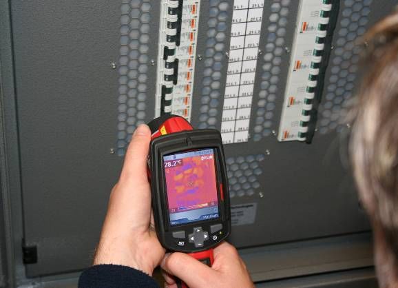
Inspection Ports
Infrared inspection ports are usually no more than
15mm in diameter (IP2X). Ports can contain either
specialty lenses or adaptors. They can be open (as
with grills) or sealed with a lens (as with viewing
panes). It is essential that the thermographer
understand whether the port is open or sealed –
this will determine whether the electrical
equipment is in an “enclosed” and “guarded”
condition, which will dictate PPE requirements.

Custom Solutions
Certain applications may require a custom solution:
perhaps metal cladding obstructs access to bus
joints, or maybe multiple connections are positioned
just behind a dead‐front panel of a PDU or MCC. In
these cases, standard IR windows may be
impracticable – or cost prohibitive. Depending on
the requirement, it is possible to design custom
windows to allow inspection of applications that may
have been previously “un‐inspectable” due to high
incident energy levels. (Note: decisions regarding
custom solutions should always involve corporate
safety officials.)

Environmental Ratings
Ingress protection and environmental integrity standards rate the suitability of a component to resist a
wet or dusty environment. The two primary ingress protection standards that apply to electrical
components are Ingress Protection (IP) and National Electrical Manufacturers Association (NEMA)
standards. (Ingress protection standards are discussed in greater depth in Chapter 7.)

When installing an IR window, it is standard practice to ensure that the IP/NEMA rating of the window is
equal to, or greater than, that of the enclosure.

Summary
    1. “Infrared window” is a generic term – there are actually several different categories of infrared
       windows available, all filling a different need.
    2. If installed on energized electrical equipment, does the window maintain an “enclosed” and
       “guarded” condition for the cabinet enclosure? Does opening the window mix the outside and
       inside environments, thereby negating the “enclosed” state?
    3. PPE requirements may differ dramatically depending upon the type of infrared window system
       used.
    4. Always seek, and document, appropriate approvals for any custom modifications.
    5. Be aware of the environmental ratings on the switchgear. Never install an infrared widow with a
       rating lower than that of the original enclosure.

10 Things You Need To Know About Infrared Windows                                                          2
Copyright © 2009 by IRISS, inc. All right reserved
Chapter 2
                                 Infrared Window Lens Materials
There are numerous types of lens materials that can be used in infrared (IR) windows. The specific
choice is usually driven by the application, environment, wavelength, and cost considerations. For
example, a mid‐wave R&D application with high ambient temperature requirements may use materials
that would be unsuitable for long wave condition monitoring of industrial applications.

Table 1 details a partial list of possible materials, but not all are suitable for use as an IR window lens.

                                           Table 1: Materials used in IR industry

What is the best Material for an Infrared Window?
Germanium and Zinc Selenide are among the best broadband infrared transmitters available. Sapphire is
a great transmitter in the mid‐wave (MWIR) spectrum (sometimes referred to as “short wave”). It is
incredibly durable – yet is non‐transmissive in the long wave (LWIR). Ultimately there is no easy answer
to this question because it quite simply depends on the application. In the end, thermographers must
give serious consideration to the IR window’s intended use and operating environment – installing
windows that are not compatible with the intended environment could prove to be a costly exercise
should they fail mechanically or functionally.

Does durability matter?
Will the windows be handled by scientists who will treat the optics like fragile lenses? Or will they be
attached to electric panels that will be removed periodically and placed on cement floors during “house
cleaning” shutdowns?

Mechanical stresses can fracture most crystal optics or degrade the crystalline structure, increasing
refraction and decreasing transmittance. The stresses can take the form of jarring drops, exposure to
high frequency noise or harmonics, or even exposure to environmental vibration. Incompatibility with

10 Things You Need To Know About Infrared Windows                                                              3
Copyright © 2009 by IRISS, inc. All rights reserved.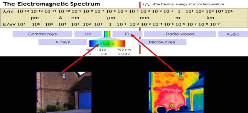
mechanical stress is one big reason why most crystals are not considered suitable for industrial
applications and uncontrolled environments.

                               Chemical           Wavelength           Reflection               Knoop              Soluble
        Material
                                Symbol               µm              (Two Surfaces)            Hardness            in H2O

    Calcium Fluoride             CaF2              0.13 – 10               5%                     158               Yes
       Sapphire                  Al2O3             0.15 – 5.5             14%                    2000                No
      IR Polymer                  N/A              0.15 – 22              21%                     N/A                No
      Germanium                   Ge                   1.8 – 23           53%                     780                No
     Zinc Selenide               ZnSe                  0.5 – 22           29%                     120                No
    Barium Fluoride              BaF2             0.15 – 12.5              7%                     82                yes
                                Table 2: Common materials used in IR window manufacture

What are the environmental factors?
Will the windows be used in a controlled laboratory environment, or will they be installed in a factory
setting or an outdoor substation?

All materials have an Achilles’ heel. Polymers would not be the answer in a kiln application. Likewise,
many crystals, such as the Fluoride family, are water soluble (also called “hydroscopic”) even when
coated. Because they cannot maintain a stable transmission rate when exposed to humidity, or
moisture, these crystals are not suited for use in most industrial applications. Carefully consider the
operating environment before choosing an infrared window lens material.

Suitability of Crystal Optics
Traditionally, Fluoride crystals (Calcium Fluoride: CaF2) and (Barium Fluoride: BaF2) were the most
commonly used infrared window optic materials. However, when Barium Fluoride was classified as a
carcinogen, CaF2became primary option.

As shown in Table 2, both BaF2 and CaF2 are hydroscopic. It has long
been a standard practice to prolong the life of these materials by
                                                                                             Modulus of Rupture
coating them in an effort to slow the inevitable deterioration due to
moisture absorption. Though the coating does slow the degradation                             Th =   √1.1(P)(DIA)²
of the crystal, there is no coating that can completely seal the entire                                  MR
crystal. The deterioration is further hastened as thermographers                      Whereas:
brush their lens casings against the coating thereby exposing the                       Th = thickness, inches
crystal surface. The greater the exposure to humidity, and moisture                     DIA = unsupported diameter,
– the quicker the crystal’s transmission deterioration.                                        inches
(Transmission stability is explored in greater depth in Chapter 3.)                     P   = pressure difference, psi
                                                                                        MR = modulus of rupture, psi
All crystal window manufacturers determine the minimum
thickness requirement for a given window diameter by calculating                          Pressure at 1 atm = 14.7 psi
its “modulus of rupture”. If the window thickness stays constant                               = 101.324 kPa
while the diameter increases. The mathematical relationship is
expressed in Figure 1.
                                                                                                        Figure 1

10 Things You Need To Know About Infrared Windows                                                                         4
Copyright © 2009 by IRISS, inc. All rights reserved.
However, you don’t need a formula to understand the concept. If                         Modulus of Rupture (psi) for
you have ever broken a stick over your knee, you know it is much                        Crystals Commonly Used in
easier to break a longer stick than it is to break a smaller piece of                   IR Windows:
the same stick. The same is true of crystals – the bigger the crystal
the more fragile it becomes, unless the thickness of the crystal is                          BaF2                3,900
increased. However, be aware that increasing the thickness of the                            CaF2                5,300
materials will decrease the transmittance of that material and will                          ZnSe                8,000
affect temperature readings (see Chapter 3 for details).                                     Ge                 10,500
                                                                                             Sapphire           65,000
The graph below traces the minimum thickness required for a
Calcium Fluoride crystal to resist a given pressure level.                                            Table 3

                       Table 4: Modulus of Rupture calculations for Calcium Fluoride at various diameters

As Table 4 illustrates, if CaF2is capable of resisting 14.7 psi (1 atmosphere) of pressure, the minimum
thickness required for a two‐inch diameter crystal is 2.8mm; a three‐inch diameter crystal should be 4.2
mm thick; and a four‐inch diameter crystal should be 5.6 mm thick. It is worth noting here that Arc
Resistant Switchgear is typically set so that plenum vents open at just 25 psi to redirect the blast forces
away from panels where personnel would be interacting with the equipment. At 25 psi (the minimum
force which a crystal window optic would experience during an arc incident) the two‐inch crystal would
have to be 3.7 mm thick; a three‐inch crystal would have to be at least 5.5 mm thick; and a four‐inch
crystal would require a minimum thickness of 7.3 mm to maintain its integrity. Thinner Calcium Fluoride
would shatter. Unfortunately, no crystal IR windows are even close to that thickness. Therefore, any
claims by a crystal manufacturer to resist the effects of an arc apply only to the integrity of the window
housing with the cover closed, and do not (and cannot) apply to the integrity of the fragile crystal.

10 Things You Need To Know About Infrared Windows                                                                        5
Copyright © 2009 by IRISS, inc. All rights reserved.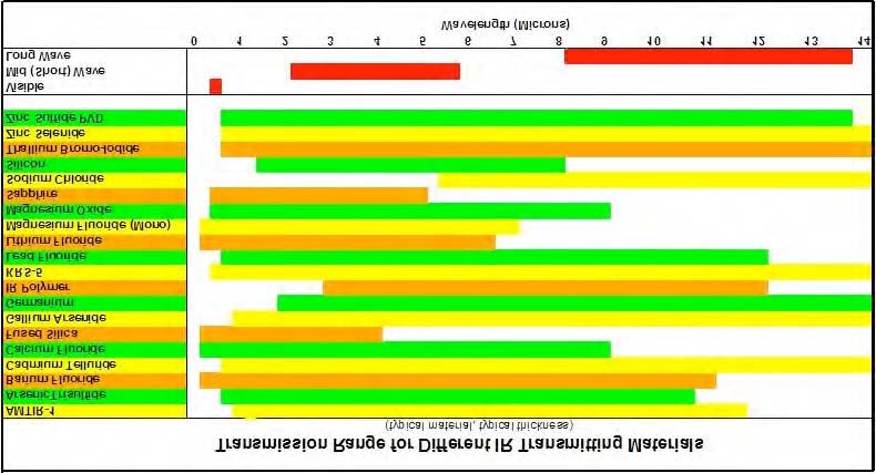
Polymeric Lens Materials
The past several years have seen a move toward the use of transmissive polymers as a lens material due
to their inherent resiliency and stability. These materials are unaffected by mechanical stress and will
suffer no effects on transmittance. They are stable: nonreactive to moisture, humidity, seawater, and a
broad spectrum of acids and alkalis – in short, they are well suited to handle the rigors of the industrial
environment.

Polymers are also extremely resilient. Because they are malleable, they will tend to absorb impact rather
than shatter. When reinforced, with specially engineered grills, the optic is capable of resisting a
sustained load. As a result, the only long wave compatible IR window optic capable of passing industry
standard impact tests (as will be explored in Chapter 7) is a reinforced polymer optic.

A reinforced polymer optic can maintain a consistent thickness regardless of window diameter because
the cells of the reinforcing material remain a consistent diameter. Consistent optic thickness means
consistent transmission rate — regardless of window size.

The only applications ill‐suited to polymer optics are those in which the ambient temperature (not
target temperature) is expected to exceed 200⁰C (392°F). Even so, like all other polymeric materials
used on switchgear, polymer windows must meet the same stringent flammability and impact tests as
prescribed by UL94. The classifications within UL94 take into consideration:

    •    Size and thickness of the part
    •    Distance from un‐insulated, live parts
    •    Hot wire ignition
    •    High current arc ignition
    •    High voltage arc tracking rate

Summary
   1. Different materials may react differently to moisture, humidity, chemicals, and mechanical
      stresses.
   2. Thermographers must fully consider the environmental factors and operating conditions to sustain
      accurate readings.
   3. IR window optics come in a wide variety of transmission rates.
   4. IR window optics come in a wide range of mechanical strength.
   5. An IR window should be functional for the life of the panel to which it is affixed. Be sure that
      warranties apply not only to the workmanship of the window housing, but also apply to the
      durability and stability of the optic in the proposed environment. For example, IRISS, inc. offers an
      Unconditional Lifetime Warranty for all its industrial‐grade windows.
   6. Seek advice from IR window manufacturers or lens suppliers before deciding what materials best
      suit an application.
   7. Consider working with a vendor that can supply IR windows made of a variety of materials, rather
      than a “one size fits all” vendor. With an array of windows optics to choose from, it is more likely
      that any peculiarities in a given application can be addressed with the most appropriate solution.

10 Things You Need To Know About Infrared Windows                                                         6
Copyright © 2009 by IRISS, inc. All rights reserved.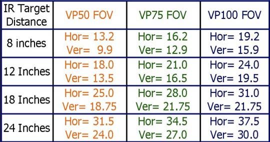
Chapter 3
            The Importance of Emissivity in Electrical Thermography
A typical factory is full of equipment that requires periodic infrared (IR) inspection. The challenge, as any
thermographer knows, is getting an accurate indication of equipment health. Properly compensating for
the various emissivity values of all the components one encounters on the factory floor is possibly the
most critical factor in performing accurate and meaningful inspections. Even slight errors in emissivity
compensation can lead to significant errors in temperature and ΔT (difference in temperature)
calculations. Electrical cabinets are a good example, as they may contain materials with emissivity values
ranging from 0.07 to 0.95.

The Science of Infrared Thermography
The electromagnetic spectrum is a continuum made up of cosmic rays, gamma rays, X‐rays, ultraviolet
light, visible light, infrared radiation, microwaves and radio waves (in order of increasing wavelength and
decreasing power). Infrared is that portion of the spectrum between 0.75µm (microns) and 1000µm in
wavelength, starting just beyond what the human eye is capable of seeing.

                                                       Figure 1

All objects above absolute zero emit infrared radiation. As an object heats up, the intensity of emitted
radiation increases exponentially (Stephan‐Boltzmann’s Law) and the peak radiation shifts to shorter
and shorter wavelengths (Planck’s Law), moving eventually into the visible spectrum. This is why a hot
burner will glow red (“incandescent”) after it achieves roughly 500°C (923°F).

Today’s radiometric IR imagers are capable of “seeing” and calculating the emitted radiation from a
target object. There are only three sources of this radiation: it can be reflected from other sources; it
can be transmitted through the object from a source behind it; or the radiation can be emitted by the
object.

Kirchhoff’s Law
An extension of Kirchhoff’s Law tells us that the sum of the radiation leaving the surface of an object
equals one: expressed as Watts Emitted + Watts Transmitted + Watts Reflected = 1 (or ε+τ+ρ=1).

10 Things You Need To Know About Infrared Windows                                                           7
Copyright © 2009 by IRISS, inc. All rights reserved.
Therefore, emitted energy, reflected energy and transmitted energy are the only three possible sources
of infrared energy coming from a target object.
An illustration of Kirchhoff’s Law is shown in
Figure 2.
Kirchhoff’s Law
A perfect emitter is referred to as a blackbody.
A blackbody emits 100% of the energy it ε +τ +ρ =1
absorbs. Since by definition there is no
reflection or transmission, a blackbody has an
emissivity value of 1. For real‐world objects
(referred to as “real‐bodies”), emissivity is
expressed as the ratio of the radiant energy
emitted by that object, divided by the energy
that a blackbody would emit at that same
temperature.
The images in Figures 3 and 4 clearly illustrate
the difference between actual and apparent
temperature. It is the same pan: one side is
aluminium and the other is Teflon‐coated. The Figure 2
Teflon coating has a much higher emissivity value.
Pop Quiz: Which one is the Teflon side?
Figure3 Figure 4
Figure 3 Figure 4
10 Things You Need To Know About Infrared Windows 8
Copyright © 2009 by IRISS, inc. All rights reserved.The graph in Chart 1 shows
how calculated temperatures
can be adversely affected
when the imager’s emissivity
value is set too high. In this
example, the emissivity of the
target is 0.50; the graph
shows the apparent
temperature when the
imager’s emissivity setting is
stepped down from 1.0 to
0.50. When emissivity is
properly compensated for,
the actual temperature is
shown to be 12.2° higher.
Chart 1
Magnitude of Error
One of the most misunderstood concepts in thermography is the
degree to which errors in emissivity settings (and errors in Stefan‐Boltzmann Law
window transmissivity compensation) will affect temperature and W = εσΤ4
ΔT (difference in temperature) accuracy. As demonstrated by the Whereas:
W = Total Radiant Power in Watts/m2
Stefan‐Boltzmann Law (Figure 5), the radiated infrared energy
ε = Emissivity (unitless)
emitted by a target surface is exponentially related to the σ = Stefan‐Boltzmann Constant
absolute temperature of that surface. (1.56X10‐8W/m2K4)
T4 = Absolute Temperature in Kelvin
Therefore, as the temperature increases, radiant energy increases
proportionally by the absolute temperature to the 4th power.
Incorrect camera settings such as emissivity and infrared window Figure 5
transmission rates will result in errant temperature values.
Furthermore, because the relationship is exponential, this error will worsen as the component increases
in temperature. Consider the effect on ΔT comparisons, which are by their nature a comparison
between different temperatures. The resulting calculations are apt to be radically understated, which
could easily lead thermographers to misdiagnose the severity of a fault.
Emissivity Standardization
For some components, it can be difficult to determine the correct emissivity value. In the case of a
highly polished component like a bus bar, the actual emissivity may be so low as to make temperature
measurement impractical. It is strongly recommended that thermographers understand the surface of
the primary targets. Once identified, those surfaces should be treated with a high‐emissivity covering so
that all targets have a standardized emissivity. Thermographers can apply electrical tape, high‐
temperature paint (such as grill paint), or high‐emissivity labels (like the IR‐ID labels from IRISS). When
all targets have a standard emissivity, refection issues are minimized and measurement errors from
reflected ambient energy are greatly reduced. High‐emissivity targets of varying shapes can also provide
a useful point‐of‐reference both for the thermographer and the technician making repairs.
10 Things You Need To Know About Infrared Windows 9
Copyright © 2009 by IRISS, inc. All rights reserved.24.6 C
20.2
°C
C
Figure 6 Figure 7
The image in Figure 6, a thermogram of the interior of a piece of switchgear, appears to show a wide
variation in temperature. Can you identify some faults? In reality, this switchgear is new and has never
been energized. The differences in shading in the thermogram are all due to reflection issues. The digital
photo (Figure 7) shows that the thermographer has placed a piece of electrical tape around one area of
the bus bar. The tape in the thermogram shows the true temperature of the reflective bus. The moral of
the story: A picture might be worth a thousand words, but a thermogram is not worth the paper it’s
printed on unless emissivity is standardized (or Known).
Summary
1. Emissivity is one of the most important variables a thermographer must understand.
2. Whenever possible, know the emissivity of your target and compensate for it using the
emissivity setting on the camera.
3. Incorrect emissivity settings can have a significant effect on the accuracy of qualitative and
quantitative data (thermograms and temperature calculations).
4. Using an emissivity value that is higher than the actual emissivity of the target will result in
electrical faults appearing cooler than they actually are.
5. Emissivity errors are not linear, but are exponential in nature (Stephan‐Boltzmann’s Law). The
exponential nature of the error also means that ΔT values (differences in temperature) can be
greatly affected by the errors as well.
6. When installing IR windows it is important to standardize the emissivity of the targets while
the gear is open (and assumedly de‐energized).
7. Common treatments for target surfaces are: grill paint, electrical tape and IRISS IR‐ID labels.
Pop Quiz Answer: The Teflon side is Fig 3. Fig 4 is the stainless steel side which appears cooler than
Fig 3 because it is reflecting the cooler background temperatures.
10 Things You Need To Know About Infrared Windows 10
Copyright © 2009 by IRISS, inc. All rights reserved.Chapter 4
Know Your Infrared Window Transmittance
Maintenance professionals can use infrared (IR) cameras to take both qualitative (image only) and
quantitative (temperature measurement) images. To ensure that quantitative images are accurate, it is
important to understand what other variables in the external environment can lead to possible
measurement errors.
In addition to reflection and emissivity, distance, humidity and camera angle can all play an important
role in accurate temperature measurement. But when thermographers use IR windows, improper
window transmission compensation can easily affect apparent temperature and apparent ΔT
calculations by 30% and more.
Infrared inspection windows have become an industry standard way to facilitate infrared electrical
inspections while increasing both the safety and the efficiency of the inspection process. While window
optics can be made of a variety of different materials, they generally fall into one of two categories:
crystal or polymer. It is important for the thermographer to know the transmission rate of the window
being used. However, some crystal windows that look similar might actually be made from different
materials, causing the transmission rates of two apparently similar windows to be very different. Even
the same crystal material from the same manufacturer may be cut to different thicknesses. This
difference will cause the thicker crystal to have a lower transmission rate than a thinner lens of the
same material. These potential sources of variation underscore the importance of understanding the
characteristics of the inspection window being used.
The graph in Chart 1 below demonstrates the degree to which transmission rates of different materials
will change across the IR spectrum. Note that some materials will be unsuitable for use with a LW
camera (as is the case with sapphire, Al2O3). Other materials, such as Zinc Selenide (ZnSe) are well suited
for use with both MW and LW – these materials also tend to be more expensive for that reason.
Chart 1
10 Things You Need To Know About Infrared Windows 11
Copyright © 2009 by IRISS, inc. All rights reserved.Given the transmission variability across different wavelengths, one needs to define the transmission
rate at a specific wavelength. Our research shows that this “PdM” wavelength is at about 9µm in the LW
band and about 4µm in the MW (SW) band.
For accurate temperature calculations, it is irrelevant whether the window’s transmissivity coefficient is
90%, or 50%... or something in between. What is important is that the thermographer knows the exact
transmission rate. Then when the thermographer enters the correct coefficient into the camera or
software, the final temperature calculation will be accurate and reliable. If, however, the thermographer
is not aware of the actual transmission rate, or does not adjust for it, the errors can be significant.
Kirchhoff’s Law and Infrared Windows
As discussed in Chapter 3, Kirchhoff’s Law shows us that the total infrared radiation a camera receives is
actually composed of the total emitted, reflected and transmitted radiation from an object. With this in
mind, the ideal window would therefore be one that allows 100% transmission, i.e. zero loss to
emittance and reflection. To maximize transmittance, and minimize emittance and reflectance values,
manufacturers carefully select optic materials and window coatings for their performance in specific or
general wave bands. Unfortunately, as Chart 1 depicts, with the materials presently available, 99% is the
highest transmission rate available (coated ZnSe in the LW portion of the spectrum).
The graph in Chart 2 shows how calculated temperatures can be adversely affected when a
thermographer improperly compensates for transmission. In this example, the transmission rate of the
IR window is 0.50. The graph shows the apparent temperature when the imager settings are stepped
down from 1.0 to 0.50. When transmission is properly compensated for, the actual temperature is
shown to be 11.8° higher: very similar to the effects of emissivity compensation discussed in Chapter 3.
Chart 2
10 Things You Need To Know About Infrared Windows 12
Copyright © 2009 by IRISS, inc. All rights reserved.All window optics will filter, or “attenuate” the amount of infrared radiation that ultimately reaches the
imager. Our research shows that for calcium fluoride windows the attenuation reduces the temperature
about 5% for every millimeter of window thickness (temperatures in the range of 60°‐120°C). In
addition, tilting the camera angle 30° to either side of 90° (perpendicular) reduces the temperature by
an additional 2‐3%.
Compensate for Transmission
A simple way to check transmission rate, is the “Coffee Cup
Test” (see Table 3). After determining the proper transmission The “Coffee Cup Test”
rate of a window, make a note of that value and adjust the A simple way to check the transmission
camera’s transmission rate (or emissivity setting) accordingly rate, of an IR window is to do the “coffee
each time that window is used for an inspection. cup test”. Note that this test should be
completed both on initial install – and
The majority of infrared cameras do not have the ability to during regular window maintenance for
windows that use materials that are known
compensate for transmission losses from an IR window directly;
to degrade over time.
but almost all software packages do. To make a quick
adjustment in the field, simply multiply the transmission 1. Get a cup of warm water, and place a
coefficient by the target emissivity to arrive at a “calculated target of known emissivity on the cup
emissivity value,” and adjust the camera’s emissivity setting to surface (electrical tape, emissivity
this value. For example, an IR window with a 0.55 transmittance label).
rate and a target with an emissivity of 0.95 (electrical tape) 2. Set the camera’s transmission (if
would require a camera emissivity setting of 0.49 (0.90 x 0.55 = available) and Emissivity to 1.0.
0.495) to properly compensate for both transmission and 3. Measure the temperature of the
emissivity. target without the window.
4. Place the window in front of the
camera and complete the exercise
Degradation again.
Once the transmissivity coefficient has been properly 5. Using either the camera, or the
determined for an application, it is important to realize that camera reporting software, change
coefficients of some materials can change over time. Crystals, in the transmission coefficient on the
particular, are susceptible to mechanical stress from high image until the adjusted temperature
frequency noise and vibration. Some crystals, such as those in is the same as the original image
the Fluoride family are also hydroscopic; meaning that they will temperature.
absorb moisture, humidity or industrial solvents (despite the 6. Record the new transmission rate on
the window label and in the report
fact that they are coated with materials to slow the inevitable
template for future use.
degradation process). These mechanical stresses and absorption
characteristics of crystals will degrade a crystal window’s
transmission rate over time.
A recent paper on the topic of transmission degradation (“Transmission Stability and Infrared Windows”
by Joe DeMonte) illustrates how this degradation can affect the data accuracy. The research compared a
Calcium Fluoride infrared window to a polymer‐based window. Both windows were shown to have a
50% transmission rate when new. After just two years in a non‐aggressive environment, the
transmission rate of the calcium fluoride window had dropped significantly.
10 Things You Need To Know About Infrared Windows 13
Copyright © 2009 by IRISS, inc. All rights reserved.Figure 1 Figure 2 Figure 3 For the test, an overhead clamp was heated to a stable temperature. The target was a bolt head that was covered with a piece of electrical tape with an emissivity value of 0.95. Figure 1 shows the target viewed without an infrared window. The temperature was shown to be 115.8°F. In preparation for viewing through the infrared windows, the transmission rate was adjusted to 50% in accordance with the rate defined two years prior (as discussed above). When the polymer window was placed in front of the camera (see Figure 2), the registered temperature was 115.9°F. When the target was viewed through a Calcium Fluoride crystal window the apparent temperature of the 115.8°F target registered just 82.4°F (as seen in Figure 3) due to the degradation in the crystal’s transmission rate. The result of this study clearly underscores the importance of compensating for the actual transmission rate of the IR window optic. In this case, the resulting measurement error is over 28%. (For additional information, this white paper which was published in the April 2009 edition of Uptime Magazine can be found at http://www.iriss.com/PDF/new_white_papers/Transmission_Stability_and_Infrared_Windows_030309.pdf Recalibration of Window Transmittance The “Coffee Cup Test," or some similar form of verification, should be performed prior to installation – and again prior to any important measurement or inspection if using an optic that is known to degrade over time. Furthermore, because each crystal is unique, transmittance must be tested for each crystal since each one will have a slightly different transmittance rate when new. (For additional information see UpTime Magazine; November 2007; “Opening the Windows;” Dougherty, Newberry & Schewe: http://www.uptimemagazine.com/digi/nov_07/index.htm.) Similarly each crystal’s rate of degradation will be unique as well. However, if using an engineered polymer, testing a single window when it is new should be sufficient since all windows will be virtually identical in transmittance and since the material will not degrade over time. Maintaining IR windows During maintenance shutdowns, firms should check gaskets and screws for seal integrity, and windows should be thoroughly cleaned with a compatible cleaning agent. If using crystal IR windows, this is also a great time check transmittance. 10 Things You Need To Know About Infrared Windows 14 Copyright © 2009 by IRISS, inc. All rights reserved.
Summary
        1. Know the characteristics of the infrared window optic as it pertains to the wavelength of
           your camera (MW versus LW).
        2. Test the IR window transmittance and document the result.
        3. Compensate for the transmission attenuation for accurate temperature calculations.
        4. Re‐test each window’s transmission rate if the material is known to degrade over time (as
           with most crystal optics).
        5. Include the windows in the general maintenance of the equipment to which it is attached.

10 Things You Need To Know About Infrared Windows                                                      15
Copyright © 2009 by IRISS, inc. All rights reserved.
Chapter 5
Field of View (FOV) Through an Infrared Window
The two questions most often asked by maintenance professionals getting ready to install infrared (IR)
inspection windows on electrical equipment are: “How many windows will I require per panel” and
“What diameter window is best?” The answer is “it all depends on Field of View (FOV).” It depends on
the FOV of the camera, lens attachment (if used) and IR window.
Measurement Field of View (MFOV)
First, let’s examine the camera and lens specifications. We are primarily concerned with the MFOV
(Measurement Field of View), also referred to as the “Spot Size Ratio.”
Every camera defines its FOV across a horizontal/vertical axes. The Instantaneous Field of View (IFOV) is
the smallest target the camera can”see”. Although an IR camera can pick up numerous hot spots, many
spots will be too small to measure accurately with a radiometric IR camera (one which displays
temperature on the image). The MFOV, or Spot Size Ratio is the smallest target the imager can
accurately measure.
The greater the resolution of the camera: the better the IFOV. For example, one top‐selling camera uses
a 640 x 480 pixel array. It has a MFOV of 500:1, while a 320 x 240 camera has an MFOV of 200:1. In
these examples, a one‐inch diameter target could be measured from a distance of 500 inches (41.7 feet)
by the higher resolution camera; whereas the other camera would have a maximum distance of 200
inches (16.7 feet).
A telescopic lens (typically a 12° or 7° attached to a standard 24° lens) will also improve FOV by a factor
of 2X and 3X respectively. Therefore, a 7° lens used on that high resolution camera would allow
measurement of a one‐inch target from a maximum distance of 125 feet (1”:500 x 3 = 1500” / 12”).
Think of resolution as the quality of your eyesight. When you go to the stadium to watch your favorite
team, the poorer your eyesight, the closer you will need to be to the field to see your favorite player’s
jersey number (temperature). Watching the game from high up in the “cheap seats,” good eyesight will
help, but you may be too far away to see the detail of that jersey number. Good thing you brought those
binoculars (the 7° telescopic lens attachment)!
Window Field of View (WFOV)
Typically, IR cameras have a standard FOV of approximately 24°(horizontal) and 20° (vertical). So, it is
advisable to do calculations based on a standard lens (since a wide angle may not always be available).
Note that the calculation assumes that the FOV begins at the panel cover and extends a distance (d)
from the panel cover to the targeted components. The length along that FOV is a distance (D). D is
calculated by multiplying the distance (d) by the tangent of half the lens angle, then doubling the result.
Standard calculations assume that FOV starts at a single point, or vertex of the viewing angle. It does not
take window size into account. So for a calculated D of 2.8″ add an additional two/four inches when
using a two or four inch window (yielding a D of approximately 4.8/6.8″).
10 Things You Need To Know About Infrared Windows 16
Copyright © 2009 by IRISS, inc. All rights reservedD
The illustration in Figure 1 shows the
area inside a cabinet that can be
viewed through an IR window using Visible
AreaSurface
a camera with an 82° FOV lens. A d
typical switchgear compartment is
20 inches deep, therefore:
D = 2d x (tangent of 41°)
D = 2*20 x 0.87 = 34.8 inches Panel Cover
IR Window
41°
Figure 1: Standard FOV calculation with fixed viewing angle
The calculations in Figure 1 indicate that with an 82° FOV lens, a thermographer can view 34.8 inches
horizontally inside the panel. However, this calculation assumes the thermographer holds the camera
fixed and perpendicular to the window plane. More likely, the thermographer will vary the viewing angle
up to 30° from perpendicular in all directions. This effectively increases the FOV area by a factor of
three.
Camera Angled for 2X standard FOV
D = (2*20) x 0.87 x 2
D = 69.6 inches
Camera Angled for 3X standard FOV D = Visible Area
D = (2*20) x 0.87 x 3
D = 104.4 inches
d = cabinet depth or target distance
Figure 2: Standard FOV calculation (varying the viewing angle)
ng angle
10 Things You Need To Know About Infrared Windows 17
Copyright © 2009 by IRISS, inc. All rights reservedPractical FOV Test:
Some thermographers find it easier to let the camera show them “what it can see” rather that
completing a number of calculations. The following procedure is a quick method for working out what
can be seen at set distances with your own camera, lenses, and IR windows:
1. Place a large piece of paper on a flat even surface. Draw a line straight down the length of the
paper. Intersect the line in with 6‐inch increments, and label the marks from 0 to 36‐inches.
2. Place the camera lens at the 0‐inches line.
3. Place two heat sources (fingers, warm coffee cup, etc.) at a distance from the camera that is
typical of the targets you will be monitoring. For example, if monitoring targets that are typically
18‐inches from the switchgear panel, place your heat sources on the 18‐inch line.
4. Move one heat source from the center of the FOV, to the left, until it appears just inside the
edge of the left‐hand (LH) side of the imager display. Mark the paper at this point. Repeat the
same procedure for the right‐hand (RH) side. (See Figure 3)
FOV
Figure 3.
5. Measure the distance between the LH and RH points. The result is the maximum FOV that can
be achieved using that camera‐and‐lens combination, at the defined distance (assuming the
camera position is not changed). Make note of the FOV and of the distance from the camera.
6. To calculate the WFOV for different windows sizes used with the camera‐and‐lens combination
above, simply subtract the camera lens diameter from the FOV (noted in step 5); then add the
diameter of the IR window that you intend to use. The total is that camera’s Maximum
Horizontal WFOV, at the defined distance. Record this measurement.
Example:
FOV of a 24 degree lens at 18 inches as measured using the above process = 8 inches.
The camera lens diameter= 1.75 inches, therefore the FOV of the camera = 6.25 inches.
• Using a 2 inch IR window would give an approx FOV of 8.25 inches
• Using a 3 inch IR window would give an approx FOV of 9.25 inches
• Using a 4 inch IR window would give an approx FOV of 10.25 inches
7. Repeat the exercise with your camera turned 90° on its side. The result will be your camera’s
Maximum Vertical WFOV. (Remember that your camera sees more in the horizontal plane than
the vertical plane.)
10 Things You Need To Know About Infrared Windows 18
Copyright © 2009 by IRISS, inc. All rights reserved8. Record the results in a table like the one shown in Figure 4. (Note that these figures
were taken using a FLIR P65 IR Camera.) This FOV matrix was calculated using the above
technique and then multiplied by a factor of 3 to give the total WFOV through each type
of IRISS IR Window, allowing for roughly a 30° angle of incidence. Keep your matrix with
the camera for future reference.
Figure 4
Tip: Most thermographers will take FOV measurements at several distances that are relevant to the
various applications they monitor. Also, try moving a target as close to your camera as possible until you
can no longer bring the object into focus. This will show you the camera’s “minimum focus distance.”
i.e. the closest you can get to a target and still be in focus. It is very useful to know your camera’s
minimum focus distance, since some cameras can be more than 24 inches, thereby limiting their use in
electrical thermography.
Note: Although the above technique is not 100 % accurate it gives an extremely good result. Try it for
yourself – it is a simple technique that really works!
Rule of Thumb
Based on countless field tests for WFOV with a wide variety of cameras, most cameras have generated a
horizontal WFOV of roughly two to three times (2X to 3X) the distance to the target; and a vertical
WFOV of roughly 1.5X to 2X the distance to the target. This is based on cameras with a standard 24° or
similar lens, using a maximum angle of incidence of 30°.
Therefore, based on this rule of thumb, a window located 20 inches (51 cm) from the intended targets
would allow the thermographer to gather data from points that were separated by 40 to 60 inches (1m
to 1.5m) side‐to‐side and separated by 30 to 40 inches (0.75 to 1m) top‐to‐bottom.
Note that it is impractical to use a multiplier in excess of 3X due to the difficulty matching the thermal
image to locations within the panel. Obstructions in the panel may also make it impractical. As
previously mentioned, viewing at too steep an angle can begin to affect other variables such as
emissivity. Therefore, IRISS, inc. recommends a maximum of 3X as a “rule of thumb multiplier.
10 Things You Need To Know About Infrared Windows 19
Copyright © 2009 by IRISS, inc. All rights reservedSummary
1. Every camera has a Field‐of‐View (FOV) defined in degrees across a horizontal/vertical axis.
Note that the FOV can vary depending on the type of lens used.
2. Image Field of View (IFOV): The smallest detail that can be resolved.
3. Measurement Field of View (MFOV): The smallest detail that can be accurately measured.
4. Window Field of View (WFOV): The largest area that can be viewed through an infrared
window allowing for a maximum angle of incidence of 30° off perpendicular.
5. Rule of thumb for WFOV using a standard camera and lens is roughly 2 to 3 times the
distance from the window to the target.
6. Obstructions, such as phase dividers or cables, inside the cabinet may decrease actual field
of view.
10 Things You Need To Know About Infrared Windows 20
Copyright © 2009 by IRISS, inc. All rights reservedChapter 6
Proper Installation of Infrared Windows
Proper installation of the infrared window is critical for the long‐term use of the window and for the
long‐term performance of the panel and equipment enclosure. Although an infrared window is not as
strong as the steel it replaces, installing an IR window is no different than many other modifications that
are commonly performed on switchgear and other electrical applications. Therefore, if a company has a
policy for modifications such as: replacing or adding an ammeter or similar device, installing a visual
inspection pane or modifying a cabinet to add a new conduit run, then it is logical to include infrared
windows under the same policies. For example, one would want to refer to any existing policies relating
to: pre‐planning, design/installation approval, installation best practices and post‐installation inspection
by an in‐house or external authority.
Do Not Pass “Go”
Confirm the following prior to planning any modifications to an electrical equipment enclosure:
• Ingress Protection: Ensure that the NEMA or IP rating of the IR window or other component is
rated for at least the same level of protection that the current enclosure is rated for. Never
install an infrared window or any other component with a lower rating than the equipment onto
which it is being installed.
• Tests and Certifications: Ensure that the IR windows have been tested and approved by the
relevant certification bodies. Official test certificates and documentation should be easily
obtained from the manufacturer.
• Explosion Ratings (if applicable): Enclosures located in intrinsically safe areas should never be
modified in the field unless designs have been cleared with, and post installation inspection and
re‐certification will be performed by an Authority Having Jurisdiction prior to start‐up.
Identify All Targets
Start the process by identifying specific targets on each piece of equipment. In addition to fuses and
breakers, most infrared surveys focus on bolted connections within the gear, as these areas are
considered the weakest points. These areas include:
• Cable connections
• Bus bar connections
• Isolator or circuit breaker connections
Make a quick inspection of the interior of the switchgear to identify these targets. Once identified, make
every effort to standardize their emissivity while equipment is de‐energized. Common methods include
use of electrical tape, high‐temperature paint or IRISS IR‐ID labels. After emissivity standardization is
complete, it is important to photograph each target since these photos will be used for report templates
and future reference.
On many switchgear models, it is advisable to install viewing windows in the front and back for better
access to the main breaker and bus connections. Ask the manufacturer for drawings and suggestions
regarding the critical inspection locations for your equipment. This information, along with the
experience and knowledge of the site maintenance engineer, will prove useful when calculating window
placements and quantities.
10 Things You Need To Know About Infrared Windows 21
Copyright © 2009 by IRISS, inc. All rights reservedInstallation
Before picking up that drill, it is imperative to consider the following to ensure a successful, safe and
useful installation:
• Internal obstacles:
Seek the permission from the local safety manager before removing internal Lexan TM (Perspex)
covers. In some cases, you may not be able to remove the covers entirely. If this is the case,
modify the covers by drilling or punching holes (without losing the IP2X requirement for some
switchgear), or investigate custom guards that would allow for infrared transmission (such as
the IRISS CAP Series.)
• Internal Cable Routing: Minimum
Work from drawings on brand‐new switchgear to confirm the Maximum
Clearance
internal cable routes. Make sure that contractors do not route Voltage (kV)
In cm
these cables in front of the infrared windows.
4.76 5.5 14
• Dielectric Clearances (distance from energized components):
8.25 6.5 17
Where the IR window contains grills, or inspection orifices, it
15.0 8.0 20
must comply with IP2X (13mm 0.5”). Safe dielectric clearances
27.0 12.0 30
must be maintained for each window. IEEE C37.20.2, Table 1
specifies a minimum clearance distance for live components 38.0 15.0 36
(versus maximum rated voltage). Table 1: from IEEE C37.20.2
PPE:
Complete a detailed Risk Assessment (identifying all hazards
that may be present during the installation) and a detailed
Method Statement (detailing how the installation will be
performed). Make sure that the installation crew has the correct
levels of PPE to complete the task safely, especially if the
installation involves energized work, in which case an energized
Work Permit will also be required per NFPA 70E/CSA Z462. All
work procedures, assessments and permits must be outlined in
the Risk and Method statement.
Installation Instructions
Ensure that you comply with the Installation Instructions like those
in Figure 1, provided by the window manufacturer. These will
provide you with all the necessary information to ensure that the
windows are installed correctly.
Tools Figure 1
Before starting any installation, double‐check to be sure that all required tools are readily available.
Traditionally, IR window installations take place during plant shutdowns therefore, you will need to
ensure that you have all the cutters, drills, drill bits, metal treatments, etc. already kitted and at‐hand
(including spares). Remember, that you will probably not be able to run to a hardware store to purchase
new punches at 2 in the morning! A complete list of required tools can be obtained from the IR window
manufacturer.
10 Things You Need To Know About Infrared Windows 22
Copyright © 2009 by IRISS, inc. All rights reservedLabeling
Affixing information labels is an important final step in the installation process. One label should identify
what the window is and how to use it. A second sticker should contain the following information that
will be critical in performing a thorough and accurate infrared inspection:
• Each inspection window should be given a unique number. This will be invaluable, especially, if
there are multiple windows on one electrical panel.
• Document the type of window (MW or LW) and the effective wavelength of the window (as
detailed in Chapter 2).
• Record the transmission rate of the window, and the proper transmission compensation value
for the MW and LW.
• Record all target data on the on the ID label. The most common method of documenting target
location is the clock face method: i.e. bus bar connections at 4 o’clock. It should be noted that
there may be multiple targets being surveyed through the IR window.
• Some cameras do not have the ability to adjust the external optics transmission; therefore,
thermographers may use the emissivity settings on the camera to cover transmission and
emissivity losses. Multiply the target emissivity by the transmission rate of the window (as
detailed in Chapter 4).
IRISS VP100 INSTRUCTIONS FOR USE
CAUTION: THIS DEVICE IS INCOMPLETE WITHOUT THE COVER FITTED
Undo both protective cover locking screws two complete turns.
Slide protective cover down and rotate cover anti‐clockwise.
Take thermographic image (Remember to record data from IR window:
location, transmission rate, etc).
Rotate cover clockwise against the upper locking screw and slide
upwards to locate cover.
Fully tighten all four locking screws. (Min 0.2 Nm)
LOCATION: MCC1 North Plant Room
IR WINDOW NO: No 2
LENS MATERIAL: IR Polymer
TRANSMISSION: SW 55% LW 68%
NOTES:
BUS BAR CONNECTIONS: 3 O’CLOCK: E = 0.95
BUS BAR CONNECTIONS: 8 O’CLOCK: E = 0.95
Figure 2
Baseline
After the window installation is completed, the thermographer should conduct a benchmark inspection
to set the base line. Data for each inspection point should be recorded in a spreadsheet or database for
trend analysis over several surveys. There are software programs available to assist with database
management and trending of infrared data.
10 Things You Need To Know About Infrared Windows 23
Copyright © 2009 by IRISS, inc. All rights reservedWhat Can I See Through an Infrared Viewing Pane?
An infrared window allows you to check the condition of electrical conductors and circuit parts. As with
traditional thermographic inspections, the camera is very good at detecting and displaying even slight
temperature differences very clearly. Therefore, when there is an electrical fault producing a
temperature rise, the camera will display the image of the faulty components very clearly. However, if
everything is at temperature equilibrium, it is difficult for the camera to display an image showing much
of anything.
Figures 3, 4 and 5 are images taken through an IR window — no apparent faults are present.
Figure 3 Figure 4 Figure 5
Figures 6, 7 and 8 are images taken through an IR window — temperature rise due to load imbalance
and poor connections are evident.
Figure 6 Figure 7 Figure 8
10 Things You Need To Know About Infrared Windows 24
Copyright © 2009 by IRISS, inc. All rights reservedSummary
1. Do your homework first: check all applicable certifications and ratings.
2. Gather as much information as possible, while the equipment is deenergized.
a. Take high quality digital pictures
b. Standardize the target emissivity
c. Make detailed measurements
d. Note any internal obstacles
e. Conduct any outstanding maintenance tasks
3. Complete a thorough Risk Analyses and Method Statement before starting energized
installations.
4. If possible, complete a specialized training program dealing specifically with installation of
infrared windows.
5. Remember to label the windows correctly, since this data will be used during future
inspections.
6. Do a complete infrared inspection at the end of the window installation in order to create
a benchmark/baseline for future inspections.
10 Things You Need To Know About Infrared Windows 25
Copyright © 2009 by IRISS, inc. All rights reservedChapter 7
Certifications and Standards
“What standards and certifications are relevant to infrared (IR) windows?” This is one the most
commonly asked questions when engineers and safety professions begin to investigate IR windows.
Trying to sort through the myriad of UL, cUL, IEEE, CSA and other standards can be a daunting task. This
chapter will attempt to clarify some of the most pertinent standards.
UL50V
The UL 50V classification for Infrared Viewports is the only standard that relates specifically to infrared
windows. It serves more as a classification than an actual standard for performance‐of‐build
characteristics. Specifically it states:
Infrared Viewports are a fixed aperture, consisting of one or more openings or a solid infrared
transmitting media, surrounded by a mounting bezel or frame, that provide a means for the
passage of infrared radiation.
The UL50V classification is actually a mix of two distinctly different product categories: the “infrared
window” (also known as IR sightglasses or IR viewing panes) and the “infrared port.” While both will
allow the thermographer to perform infrared inspections of targets located inside an enclosure or
behind a barrier, they are mechanically very different. Specifically, IR windows provide a barrier to
separate the thermographer from the environment surrounding the target. In contrast, an IR port is
essentially a hole. When opened, it effectively removes the barrier between the thermographer and the
target. This distinction becomes important when considering the Personal Protective Equipment (PPE)
implications of NFPA 70E/CSA Z462 (see Chapter 8).
UL508
UL508 covers industrial control equipment and control panels under 1500 volts. Equipment covered by
these requirements is intended for use in an ambient temperature of 0‐40°C (32‐104°F) unless
specifically indicated for use in other conditions.
UL 508A
UL508A covers industrial control panels intended for general use, with an operating voltage of 600 or
less. This equipment is intended for installation in ordinary locations, in accordance with the National
Electrical Code (ANSI/NFPA 70), where the ambient temperature does not exceed 40°C (104°F).
UL 746C
UL 746C sets the impact and flammability standards for polymeric materials used in electrical equipment
up to 1500 volts. Any plastic or polymer forming part of an infrared window must pass flammability tests
at room temperature, and must remain intact during an impact test performed at 0°C (32°F).
It is worth noting that of the crystal optics capable of transmitting in the long wave portion of the
infrared spectrum (8µm to 14µm), there are no fluoride‐based crystals capable of passing the impact
tests required in 746C. However, because they are classified as “glass” under the standard, they are not
required to test for impact as long as they are thicker than 1.4 mm.
10 Things You Need To Know About Infrared Windows 26
Copyright © 2009 by IRISS, inc. All rights reserved.You can also read