Team NimbRo's UGV Solution for Autonomous Wall Building and Fire Fighting at MBZIRC 2020
←
→
Page content transcription
If your browser does not render page correctly, please read the page content below
Accepted for Field Robotics, Special Issue on MBZIRC 2020: Challenges in Autonomous Field Robotics, to appear 2021.

                                          Team NimbRo’s UGV Solution for Autonomous Wall
                                             Building and Fire Fighting at MBZIRC 2020

                                              Christian Lenz, Jan Quenzel, Arul Selvam Periyasamy, Jan Razlaw, Andre Rochow,
                                              Malte Splietker, Michael Schreiber, Max Schwarz, Finn Süberkrüb, and Sven Behnke
                                                                       Autonomous Intelligent Systems Group
arXiv:2105.11979v2 [cs.RO] 27 May 2021

                                                                               University of Bonn
                                                                                 Bonn, Germany
                                                                             lenz@ais.uni-bonn.de

                                                                                             Abstract

                                                  Autonomous robotic systems for various applications including transport, mobile manipula-
                                                  tion, and disaster response are becoming more and more complex. Evaluating and analyz-
                                                  ing such systems is challenging. Robotic competitions are designed to benchmark complete
                                                  robotic systems on complex state-of-the-art tasks. Participants compete in defined scenarios
                                                  under equal conditions. We present our UGV solution developed for the Mohamed Bin Za-
                                                  yed International Robotics Challenge 2020. Our hard- and software components to address
                                                  the challenge tasks of wall building and fire fighting are integrated into a fully autonomous
                                                  system. The robot consists of a wheeled omnidirectional base, a 6 DoF manipulator arm
                                                  equipped with a magnetic gripper, a highly efficient storage system to transport box-shaped
                                                  objects, and a water spraying system to fight fires. The robot perceives its environment us-
                                                  ing 3D LiDAR as well as RGB and thermal camera-based perception modules, is capable of
                                                  picking box-shaped objects and constructing a pre-defined wall structure, as well as detect-
                                                  ing and localizing heat sources in order to extinguish potential fires. A high-level planner
                                                  solves the challenge tasks using the robot skills. We analyze and discuss our successful par-
                                                  ticipation during the MBZIRC 2020 finals, present further experiments, and provide insights
                                                  to our lessons learned.

                                         1     Introduction

                                         Autonomous robotic systems have a large potential for future applications, including transport, mobile
                                         manipulation, manufacturing, construction, agriculture, and disaster-response. Robots can assist humans
                                         in physical demanding or highly repetitive work, such as industrial construction or transportation tasks.
                                         Especially for disaster-response applications, robots are a useful tool which can be deployed in dangerous
                                         environments to reduce the risk on humans. Autonomous behavior reduces the cognitive load on operators
                                         and allows for deployment in communication-constrained situations.

                                         Evaluating complex robotic systems as a whole under realistic conditions is challenging. Robotic competi-
                                         tions such as the DARPA Robotics Challenge or the Mohamed Bin Zayed International Robotics Challenge
                                         (MBZIRC) are designed to compare approaches on a systems level. Participants at such competitions are
                                         motivated to advance the state of the art in the domain of interest by working on complex systems designed
                                         to solve the specified tasks. They have the opportunity to test their systems at the competition event in
                                         realistic scenarios and compete against other teams under equal conditions.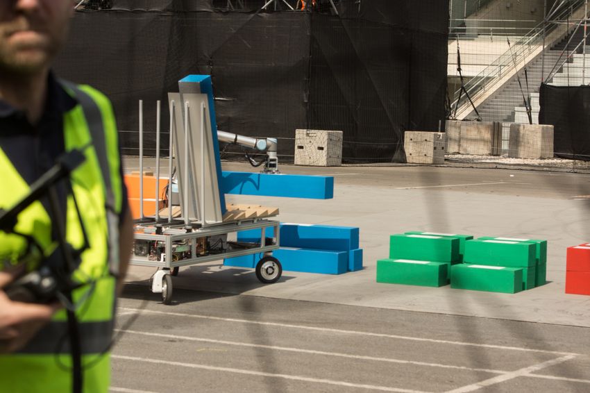
Figure 1: Our UGV Bob during Challenge 2 (left) and Challenge 3 (right) at the MBZIRC 2020 Finals.

In this article, we present our unmanned ground vehicle (UGV) designed to solve wall building and fire
fighting tasks in Challenges 2 and 3 of the MBZIRC 2020 finals (see Fig. 1). In addition to describing and
analyzing our integrated system, we discuss lessons learned and detail our technical contribution, including:
A precise laser-based registration and navigation module, a laser-based pose estimation and registration
module for the box-shaped objects, a highly space- and time-efficient box storage system, robust 3D fire
localization using thermal cameras, and an efficient high-level planner for construction.

2    MBZIRC 2020

The Mohamed Bin Zayed International Robotics Challenge (MBZIRC) is a biennial international robotics
competition. The second edition held in early 2020 consisted of three different challenges and a Grand
Challenge combining all three challenges. In contrast to Challenge 1 allowing only unmanned aerial vehicles
(UAV), Challenges 2 and 3 were designed to be solved by a team of (up to three) UAVs and an unmanned
ground vehicle (UGV).

In Challenge 2, the robots had to pick, transport, and place bricks to build a wall. Four different brick
types with 20×20 cm cross-section were used: Red (30 cm length, 1 kg), green (60 cm, 1.5 kg), blue (120 cm,
1.5 kg), and orange (180 cm, 2 kg). Each brick had a ferromagnetic patch allowing a magnetic gripper to
manipulate them. Each type of robot had a designated pick-up and place area inside the arena (40×50 m).
Fig. 2(left) shows the brick specifications and arrangement of the bricks for the UGV at the beginning of the
task. The robots had to build the first wall segment using only orange bricks. For the remaining segment, a
random blueprint defining the order of the red, green, and blue bricks was provided some minutes before the
competition. Points were granted for correctly placed bricks. The UGV could achieve 1-4 points per brick
(45 bricks in total). The time limit for this challenge was 25 min.

Challenge 3 targeted an urban fire-fighting scenario for autonomous robots. A team of up to three UAVs
and one UGV had to detect, approach and extinguish simulated fires around and inside a building. Each
fire provided a 15 cm circular opening with a heated plate recessed about 10 cm on the inside. Holes on the
outside facade were surrounded by a ring of propane fire, while indoor fires had a moving silk flame behind
the thermal element. Each fire granted points based on the difficulty reaching the location, scaled by the
amount of water (up to 1 l) the robots had delivered to extinguish the fire. Fig. 2(right) shows the simulated
indoor fire to be extinguished by the UGV.

All tasks had to be performed autonomously to achieve the perfect score. The teams were allowed to call a
reset at any time to bring the robots back to the starting location. Resets did not result in a point penalty,
but no extra time was granted.
3    Related Work

Mobile Manipulation in Industrial Automation: Many examples of mobile manipulation robots exist. For
example, Krueger et al. (2016) developed a robotic system for automotive kitting within the European FP7
project STAMINA. They mount an industrial manipulator arm on a heavy automated guide vehicle platform.
Krug et al. (2016) introduce APPLE, a mobile manipulation robot based on a motorized forklift. The system
is capable of autonomous picking and palletizing using a Kuka iiwa manipulator arm. In contrast to these
systems, our robot has to perform a less-defined task in an unstructured environment under diverse lighting
conditions.

UGVs for Wall Building: The application of robots for wall-building has a long history (Slocum and Schena,
1988). One particularly impressive example is the work of Dörfler et al. (2016) who developed a heavy mobile
bricklaying robot for the creation of free-form curved walls. An alternative for creating free-form walls is
on-site 3D printing with a large manipulator arm (Keating et al., 2017). In contrast to these systems, our
robot is able to fetch bricks from piles autonomously.

UGVs for Disaster Response: Our work mostly relates to disaster-response robotics, where protective or
otherwise functional structures have to be built quickly and with minimal human intervention. The DARPA
Robotics Challenge (Krotkov et al., 2017) established a baseline for flexible disaster-response robots. More
recent disaster-response robot systems include WAREK-1 (Hashimoto et al., 2017), a four legged robot,
CENTAURO (Klamt et al., 2019), a complex robot with an anthropomorphic upper body and a hybrid
legged-wheeled base, and E2-DR (Yoshiike et al., 2019), a humanoid robot. In comparison to these, our
system has a much higher degree of autonomy, but is more specialized for the task at hand.

UGVs for Fire Fighting: Commercially available ground vehicles for remote fire fighting include the Ther-
mite (Howe and Howe Technologies, 2020) and LUF (LUF GmbH, 2020) tracked platforms with steerable
nozzle. They are directly controlled from a safe distance by a fire fighter. Cooperative monitoring and
detection of forest and wildfires with autonomous teams of UGVs (Ghamry et al., 2016) gained significant
attention in recent years (Delmerico et al., 2019). New challenges arise where the robots have to operate
close to structures. Therefore, UGVs are often equipped with cameras and are remote-controlled by first
responders. In contrast, autonomous execution was the goal for Challenge 3 of MBZIRC 2020. Team Skyeye
(Suarez Fernandez et al., 2020) used a 6-wheeled UGV with color and thermal cameras, GPS and LiDAR.
A map was prebuilt from LiDAR, IMU and GPS data to allow online Monte Carlo localization and path
planning with Lazy Theta∗ . Fires were detected via thresholding on thermal images. The fire location was
estimated with an information filter from either projected LiDAR range measurements or the map. A water
pump for extinguishing was mounted on a pan-tilt unit on the UGV.

Although our general approach is similar to team Skyeye, we rely more heavily upon relative navigation for
aiming at the target after initial detection and less on the quality of our map and localization. In comparison,
the placement of the hose on the end-effector of the robot arm on our UGV gives us a better reach. For
detailed descriptions of our UAV/UGV team’s participation in Challenges 2 we refer to (Lenz et al., 2020).

MBZIRC 2020: (Stibinger et al., 2021) developed a UGV for the MBZIRC 2020 Challenge 2. The robot
uses a 3D LiDAR sensor for environment sensing and an RGB-D sensor mounted at the endeffector for
visual feedback during the grasping process. Compared to Bob, their solution is much smaller and thus,
can transport fewer bricks. Additional color information is used to detect and localize the bricks. A UGV
for Challenge 3 was developed by (Raveendran et al., 2020). Again, a 3D LiDAR sensor is used for SLAM.
Additional RGB-D camera measurements perceives the environment to detect the target objects (fires) using
Darknet. Our solution in comparison relies on thermal information only for detecting the fires.

MBZIRC 2017: The first edition of the MBZIRC competition also featured a UGV task: Autonomous
manipulation of a valve using a wrench selected and grasped by the robot. While the overall task is different,
many subtasks remain similar, such as reliable and fast autonomous navigation, the usage of force sensing
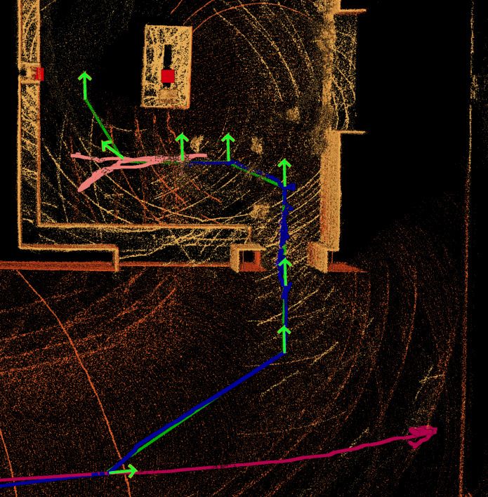
Figure 2: Left: Piles of bricks to be picked up by the UGV in Challenge 2. Right: Simulated indoor fire in
Challenge 3.

for manipulation, and so on. Our own, winning system for MBZIRC 2017, the UGV Mario (Schwarz et al.,
2019), serves as the basis for this work. It featured a fast omnidirectional base with brushless hub motors,
which carried a Universal Robots UR5 arm for mobile manipulation. Another notable entry are Bilberg
et al. (2019), who attained second place in the UGV challenge with their system built on top of a four-
wheeled skid-steer vehicle. For manipulation, they also employed a UR5 arm, but with very sensitive force
sensing capabilities, which replaced other sensing modalities such as LiDAR—detecting and measuring the
manipulation targets by touch alone.

For detailed descriptions of our MAV/UGV team’s participation in MBZIRC 2020 Challenge 2, we refer to
Lenz et al. (2020).

4     Hardware Design

We build our ground robot Bob based on our very successful UGV Mario, which won the first MBZIRC
competition (Schwarz et al., 2019). We improved the basis slightly and adapted the manipulator and sensors
for the new challenges. Since 45 bricks had to be picked, transported, and placed in 25 min to obtain a
perfect score for Challenge 2, we developed our UGV to store as many bricks as possible, complying to the
size restrictions for the competition. A much smaller robot platform would have been sufficient to carry
the components needed for Challenge 3, but would have increased the overall competition complexity using
an additional system. Thus, we extended Bob with a water storage for up to 10 liters and two windscreen
washer pumps as our fire extinguish components for Challenge 3. A 3D LiDAR scanner, two Logitech Brio
webcams and a FLIR Lepton 3.5 thermal camera are used as visual sensors for both challenges.

4.1   Omnidirectional Base

The base has a footprint of 1.9×1.4 m to provide enough space for our storage system. It rolls on four direct-
drive brushless DC hub motors, controlled by two ODrive driver boards. Since the motors were originally
intended for hover boards, i.e. personal conveyance devices, they have enough torque to accelerate the
approx. 90 kg UGV. To achieve omnidirectional movement, we coupled each wheel with a Dynamixel H54-
200-S500-R servo which rotates it around the vertical axis (0◦ caster angle). The developed base supports
driving speeds of up to 4 m/s as well as very slow speeds
Belt drive
                                                                                                        Servo motor

                              Fully loaded configurations

                                         6 DoF arm
                                                      3D LiDAR and                15◦ Bin inclination            Storage
                                                        thermal and
                                                                                                                movement
                                                        RGB camera

                                                     Magnetic gripper

                                                            5 storage bins

                                          Base with PC, controllers,
                                            WiFi router and battery
                                                                             Actuated compartments
 Steerable wheel
                                       3 DoF storage system

Figure 3: Left: UGV hardware design. Top: The storage system is capable of holding either 10 orange bricks
(left) or all remaining bricks (20 red, 10 green, 5 blue) (right). Right: Actuated storage system.

gripper, the sensors, and the bricks (up to 2 kg). In addition, the arm is equipped with a force-torque sensor
at the last link, which was used for detecting contact between the gripper or the attached brick and the
environment. We adapted the arm controller to work with UGV battery power.

The UGV is equipped with a standard ATX mainboard with a quad-core Intel Core i7-6700 CPU and 64 GB
RAM. A discrete GPU is not installed but could be easily added if necessary for future applications. The
whole system is powered by an eight-cell LiPo battery with 20 Ah and 29.6 V nominal voltage. This allows
the robot to operate for roughly one hour, depending on the task. A microcontroller (Arduino Nano 3) is
used to control eight electromagnets and two windshield washer pumps for Challenge 3.

A Logitech Brio camera is mounted at the rear-top of the robot and is used for operator situation awareness
only. Originally a GPS & IMU module was added to improve the localization. It turned out that the
wheel odometry and local localization using the 3D LiDAR sensor were good enough for the precise global
positioning required in Challenge 3, as demonstrated by the successful fire extinguish run. Thus, the GPS
module was not used and finally removed. In Challenge 2, only wheel odometry was used for localization
purposes. Precise positioning relative to the relevant objects was achieved using the perception modules
which tolerated misalignments of at least 1 m.

For Challenge 3, we equipped the base with two water tanks containing 5 liters each, two windscreen water
pumps controlled by an Arduino Nano v3 microcontroller and protected the base against splashing water.

4.2    Multi Purpose End-effector

Bob’s gripper was designed to feature all required components while keeping the size minimal to reduce the
collision potential. Fig. 4 shows the gripper mounted to the UR10e arm.

For perceiving the environment, a Velodyne VLP-16 3D LiDAR sensor and a Logitech Brio RGB camera are
mounted inside the gripper. This allows to move both sensors to the required view poses during perception.
The LiDAR sensor is used to perceive the brick poses in Challenge 2 (see Section 6.1) and for navigation in
Challenge 3 (see Section 6.3). The Logitech Brio RGB camera is used in Challenge 2 only to detect the wall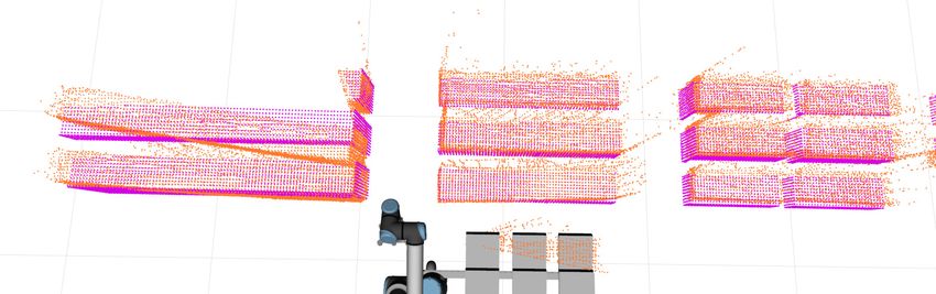
RGB Camera

                                                  3D LiDAR

                                               Thermal camera

                                            Water pipe and nozzle

                                                Contact Switch

                                               Electro Magnets

Figure 4: Front (left) and bottom view (right) of our end-effector which incorporates multiple vision sensors,
magnets for grasping purposes, a contact switch and a nozzle for water dispensation.

marker (see Section 6.1.2).

Challenge 2 required a mechanism to pick up bricks which featured a ferromagnetic part. Since the ferro-
magnetic parts of the bricks are very thin (approx. 0.6 mm), we decided to use eight smaller electromagnets
with 60 N holding force (measured using a 1 cm thick metal) to distribute the contact surface as much as
possible while keeping the total gripper size minimal. The magnets are strong enough to manipulate the up
to 2 kg heavy bricks. The gripper includes a contact switch to detect if a brick is securely grasped.

For Challenge 3, a FLIR Lepton 3.5 thermal camera was added to detect the heat source (see Section 6.2)
as well as a hose and carbon fiber nozzle at the gripper for controlled water spraying. All components are
mounted such that bricks can be grasped collision free, the gripper is not prone to self-collisions with the
manipulator, and the sensors are not obstructed.

4.3   Storage System

The storage system was designed to provide space for as many bricks as possible storing the bricks securely
in a known pose on the robot which is reachable by the arm (see Fig. 3). To achieve these requirements, the
storage system has three individual actuated storage compartments. Each compartment has five bins to store
bricks. The ground plate of each bin is 20.5 cm wide, 20 cm long and is mounted inclined 15◦ backwards.
This inclination forces the bricks to slide in a known pose inside the storage system even if the bricks are
grasped imprecise. Therefore, we do not need an additional perception system to perceive the current pose
of the stored bricks.

Side walls hold the bricks in place during UGV movements. The walls are 110 cm high which is sufficient
to hold the largest bricks (180 cm long) in place. Furthermore, this system allows to stack multiple small
bricks (up to 4 red bricks, and up to 2 green bricks) to increase the number of bricks to be stored in the
system. Overall, the system is capable to store either all large bricks (10 orange), or all remaining bricks
(20 red, 10 green, 5 blue, see Fig. 3). The bricks are stored sorted by type. This allows to unload any brick
type without needing to re-sort the storage system. Since the storage system exceeds the workspace of the
UR10e, each compartment can be moved horizontally (using a Dynamixel Pro L42-10-S300-R and a linear
belt drive) to put the desired bin in reach of the arm.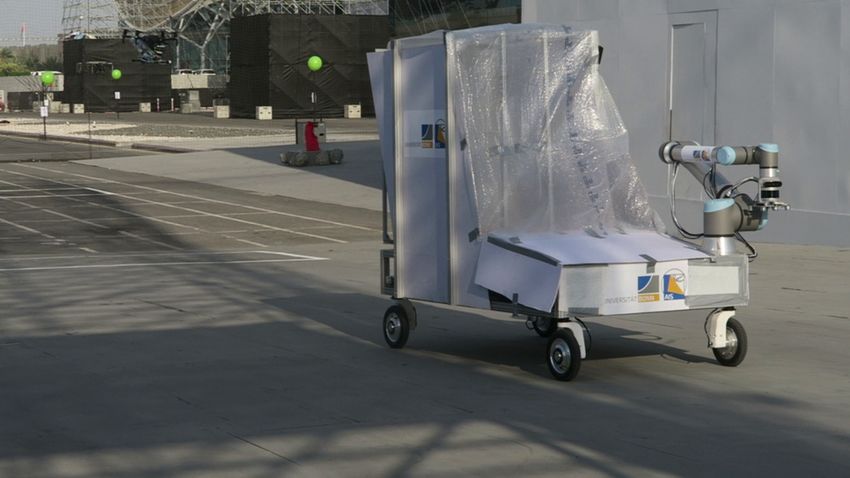
5     High-level Control

Instead of starting software development from scratch, we extended and further improved several components
from our MBZIRC 2017 entry. We build our software on top of the ROS middleware (Quigley et al., 2009),
the de facto standard framework for robotic applications.

Finite state machines (FSM) are a standard tool for definition and control of robot behavior. For relatively
constrained tasks such as the ones defined by MBZIRC, they allow fast construction of behaviors. Instead
of working with standard ROS tools such as SMACH, a Python-based FSM framework, we decided to develop
our own nimbro fsm21 library with a focus on compile-time verification. Since testing time on the real
robots is limited and simulation can only provide a rough approximation of the real systems, it is highly
likely that the robot will encounter untested situations during a competition run. We trade the ease-of-use
of dynamically typed languages and standard frameworks against compile-time guarantees to guard against
unexpected failures during runtime.

The nimbro fsm2 library supports FSM definition in C++. The entire state graph is known at compile time
through the use of C++ metaprogramming features. The library also automatically publishes monitoring
data so that a human supervisor can see the current status. An accompanying GUI displays this data and
can trigger manual state transitions, which is highly useful during testing.

We developed two separate FSMs as high-level controllers for both challenges. Common behavior such as
navigation, or arm movement states was used for both challenges.

5.1   Challenge 2

The high-level controller for Challenge 2 consists of an FSM generating the robot actions, a database to
keep track of every brick relevant for the UGV, and an algorithm computing the time-optimal strategy for
a given build order.

The FSM includes 30 different states for locomotion, manipulation, perception, storage logistics, and fallback
mechanisms (see Fig. 5). After executing an action, the resulting database and FSM state was stored to
enable quick recovery after a reset.

Since the UR10 arm is very precise, we can manipulate multiple bricks from a stationary position with
perceiving the environment just once. Our overall strategy was to minimize locomotion between different
positions in front of the piles and the wall. Thus, the plan was to pick up all orange bricks and bring them
to the wall at once. After successfully building the orange wall segment, the UGV collects all remaining
bricks and builds the second wall segment. Whereas the orange wall segment (two stacks of five bricks
each) can be built from two predefined positions relative to the wall marker, the build order of the second
wall segment highly depends on the supplied blueprint and can be optimized to minimize the number of
locomotion actions.

We implemented a backtracking algorithm to find the optimum build order. To make this approach feasible
regarding run-time, we only consider building the wall from left to right, but allow starting the next layer
before finishing the previous. Let the longer wall axis (from left to right) be denoted as the x-axis. First, we
compute the set of possible place positions by P = {xi + tx |xi = center of brick i}. The place pose is shifted
by the arm reach tx = 0.675 m to place the robot such that the number of brick placement poses in reach is
maximized. Due to the wall structure, we have 7 ≤ |P | ≤ 35. We now enumerate over all possible ordered
sequences S ⊆ P . For each pi ∈ S, we build all bricks which meet the following criteria: 1.) The brick was
not built already, 2.) the brick is in reach based on the position pi , 3.) the brick is fully supported by the
ground or previously built bricks, and 4.) the left adjacent brick was built.
    1 https://github.com/AIS-Bonn/nimbro_fsm2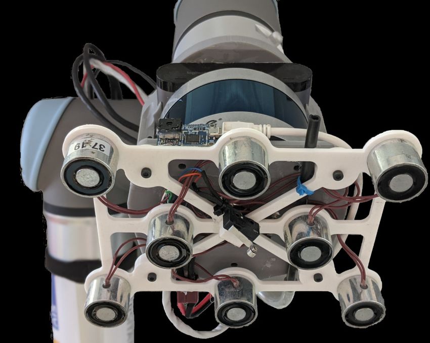
Figure 5: Graphical user interface showing all states of the FSM developed for Challenge 2. User defined
information are shown in the status bar on the right. The active state is highlighted in green. The operator
can perform state transitions manually using this GUI.

S = (p1 , p2 , . . . ) is a valid solution if all bricks are built. We search for the optimal solution with |S| and
                                P|S|
dS minimal, where dS = i=2 |pi − pi−1 |, i.e. the shortest path to traverse between all building positions.
Pruning sub-trees is used to accelerate the algorithm. Since the optimal strategy only depends on the desired
wall structure, it has to be executed just once before the competition run starts and thus longer runtimes
compared to a greedy strategy can be justified (see Section 7).

5.2   Challenge 3

The finite state machine for solving Challenge 3 consists of two main phases. First, the robot has to locate
and approach the fire. In the second phase, the robot aims the nozzle precisely at the fire and starts ejecting
water to complete the fire extinguishing task.

Fig. 6 gives an overview of our system. Details for the central state machine are shown in Fig. 7. The UGV
navigates from the start zone to the inside of the building using a set of static waypoints. In addition to
the known arena size, robot start location, and shape of the building, a map of the building and its location
was created during the rehearsal runs and thus known to the robot. The scenario specifies exactly two
static fire locations within the kitchen, one of which is burning, which we utilized by driving the UGV to
pre-determined poses roughly in front of the fire and performing a rectangular search motion with the arm.
Bob could have been equipped with a more complex search behavior to detect the fire location without any
prior knowledge of the building’s inside. We decided for the much simpler approach using the generated
offline map to increase robustness and execution speed of our system. When a heat source is detected, the
robot starts the extinguishing procedure. If not, it proceeds to the next location.

The hose is aimed so that the water jet will directly hit the heat element. The water flow trajectory was
determined experimentally for a fixed distance between the nozzle and the heat element, resulting in a
predefined arm spray pose relative to the heat element. Since the relative position estimate of the heat
source described in Section 6.2 might differ from our calibration and may also vary with distance, the aiming
process is performed in multiple 10 cm arm motions to incorporate new measurements. To further increase
chances of successfully extinguishing, the actual water spraying is split into two phases. For the first half
of the assigned water the hose is kept steady. In the second phase, the remaining water is sprayed in an
hourglass-shaped pattern by tilting the endeffector. During the Grand Challenge run the first phase already
delivered a sufficient amount of water to score maximum points. Even though we never observed the thermal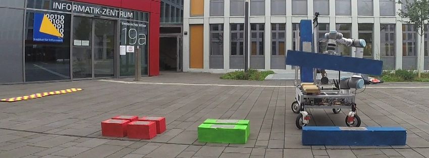
Onboard Computer

                                                                   Operator                       Thermal
                            LiDAR
                                                                   Camera                         Camera
                                                                   30 Hz Image                  8.6 Hz Image

                          Laser                                                                  Thermal
                                                                   Operator
                       Localization                                                              Detection
                                                                          Start/Stop
                                3D Position                               Command                         3D Position
                        10 Hz                                                                    10 Hz
                                3D Orientation                                                            3D Orientation
                                                                     State
                                 50 Hz         3D Target Pose
                                                                    Machine

                       Trajectory
                       Generation
                                                                          Endeffector                     Trigger
                        50 Hz Velocity
                                                                          Pose                            Command

                                                                     Arm
                                                                                                  Arduino
                       UGV Motor                                   Controller
                         Driver                                                                    Water
                                                                         Arm
                                                                                                   Pump
                  UGV Hardware

Figure 6: UGV system overview for Challenge 3. Green: Onboard Sensors and the operator input. Blue:
Software components. Red: Onboard hardware components.

detector producing any false-positives during our runs, the robot will continue proceeding to the second fire
after extinguishing the first one. The water capacity is more than sufficient with approximately 4 liters per
fire.

                                    Stop

                                                         Search Fire                                                       Extinguish
                                         No

                                   Has Next         No     Has Thermal    Yes                                Yes     Phase 2      No
           Enter Building          Location?                Detection?           Aim Hose    Stop Pump              Complete?

                                         Yes

                                                                                                   No

                                UGV Drive to              Perform Arm                          Phase 1      Yes     Spray in
               Start                                                            Start Pump    Complete?
                                  Location               Search Motion                                              Pattern

                             Figure 7: Flowchart of the Challenge 3 UGV state machine.

6    Perception

Autonomous robots base their actions on sensor measurements for perceiving their environment. We devel-
oped multiple perception modules to observe the relevant objects in the robot’s vicinity. For Challenge 2,
mainly the 3D laser measurements were used to detect and localize the box-shaped bricks. Only the marker
indicating the desired wall construction pose was invisible for the 3D laser scanner due to it’s flat (approx.
3 mm) shape. Instead, we used RGB camera images to localize the marker. Challenge 3 required precise
localization next to and inside a known mockup house. Again, the 3D laser scanner was a perfect sensor for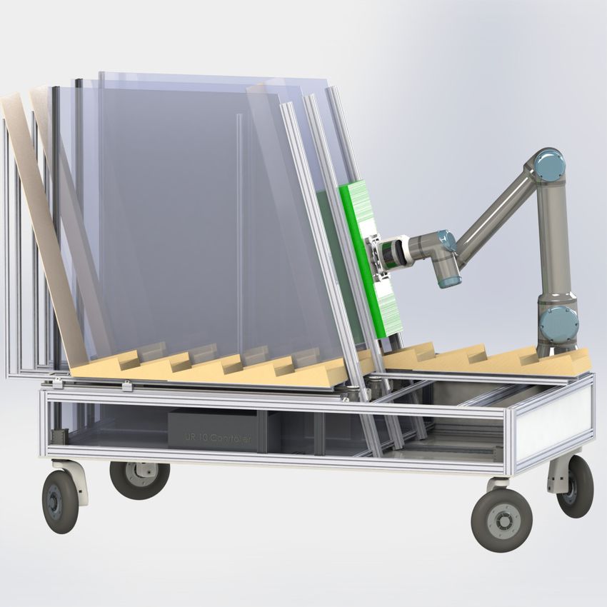
B
Trigger TW,P P Cm
Pile/Wall Render and Pile/Wall Pose
Detection Sample Estimation
B
T̃W,P
B
T̃b
Result Confidence i Individual Brick Render and
Estimation Pose Estimation Sample Bricks
Figure 8: LiDAR-based brick perception pipeline.
perceiving the building. The heat source of the simulated fire was observed using a thermal camera.
6.1 Brick and Wall Perception
When the robot is close to either the pick-up location (called pile) or the place location (called wall ), it
needs to localize against these objects and to perform pose estimation of the individual bricks in order to
pick them or place new bricks next to them. In case of an empty wall we use our wall marker detection to
locate the desired building pose (see Section 6.1.2).
Our perception pipeline assumes knowledge of the current state of the world, including a rough idea of the
brick poses relative to the pile or wall. The perception pipeline receives this information from the high-level
control module.
Depending on the target (pile/wall, denoted as P /W ), the perception pipeline receives an initial guess of the
target pose BTP or BTW w.r.t. the robot’s base (B). It also receives the brick pose W,P Tbi (W, P denotes
the considered target) and brick type ti ∈ {r, g, b, o} for each brick i. For initial alignment purposes, the
individual brick alignment can be switched off. Finally, bricks can be excluded from the optimization, for
example if they are far away and not of interest for the next action.
Figure 8 shows the overall perception process. In both cases, it starts with a rough detection of the target
location from further away.
6.1.1 Rough Pile Detection
In case of the pile, we know the approximate shape beforehand. We make use of this and search for corre-
sponding measurements using the 3D LiDAR sensor. While doing so, one needs to take care to disambiguate
the UGV and UAV piles and other distractors in the arena. The first step in detecting the pile is to con-
fine the search space to a user-defined search area, so-called geofencing. During the competition, a rough
expected location of the pile was known prior to each run which allowed restriction of the search area. In a
completely unknown scenario, the geofencing would have covered the whole arena. We start by filtering out
the points that lie outside of the search area and fit a plane to the remaining points.
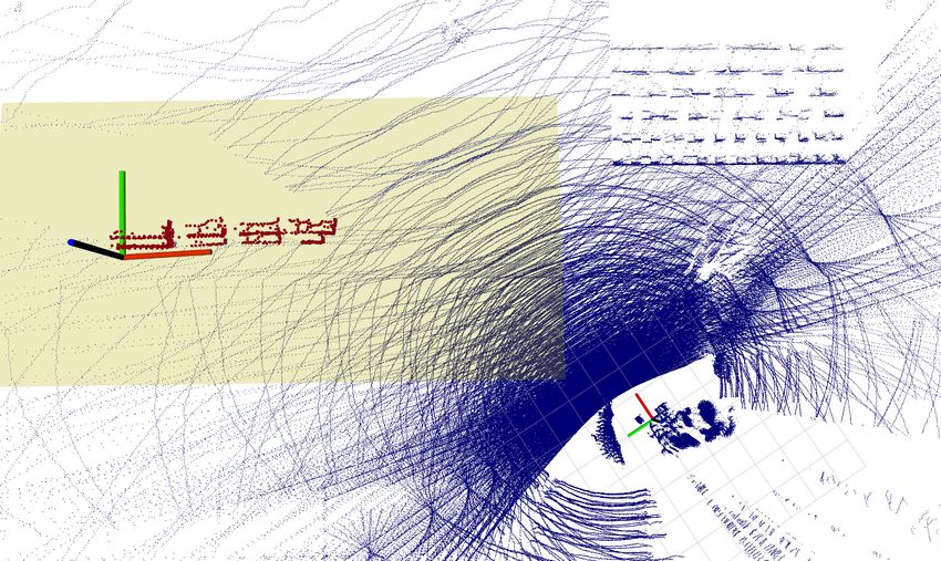
Next, we filter out the points that lie on the plane or are very close to the plane. The remaining points,
shown in Fig. 9, may belong to the pile. After clustering the points and filtering clusters which do not fit
the expected pile size, we perform principal component analysis (PCA) on the remaining cluster to estimate
the largest principal component and define the pile coordinate system such that the X axis is aligned with
the 2D-projected principal axis and the Z axis points upwards, perpendicular to the plane.Figure 9: Pile detection from LiDAR points (blue). The robot is located at the small coordinate system (bottom). The search area can be restricted using geofencing (yellow rectangle). Detected points are visual- ized in red and the estimated pile pose is shown. The scan was captured inside the competition arena during a test run. Figure 10: Wall marker detection. Starting from the input image (Col. 1), two color masks are generated (Col. 2). These masks are used for extracting corners (Col. 3 top) and clustering (Col. 3 bottom). Corners vote for clusters to detect the wall marker (Col. 4 top). Marker pose is estimated using oriented bounding box in orange around projected points (Col. 4 bottom). 6.1.2 Wall Marker Detection After picking up bricks, the next task is finding and estimating the pose of the L-shaped marker indicating where to build the wall (see Fig. 10). We use this perception module only if no bricks are already built. In case of a partially built wall we localize against the 3D brick shape (see Section 6.1.4). Our idea for detecting the marker relies on its distinctive color, pattern and shape best visible in camera images. We use the RGB camera mounted in the endeffector for this purpose. We start by specifying volumes within the HSV color space corresponding to the yellow and magenta tones of the marker. Now, we exploit the characteristic color composition of the marker to filter out distractors in the image. For that, we generate a color mask using all yellow pixels that are close to magenta pixels and another one for magenta pixels in the vicinity of yellow pixels (Fig. 10 Col. 2). The resulting masks preserve the pattern of the marker which we utilize to filter out further distractors. First, we extract the corners from each mask separately and then search for those corners present in close vicinity in both masks. Additionally, we fuse both masks and extract clusters of all masking pixels (Fig. 10 Col. 3). Next, we let each resulting corner vote for its corresponding cluster. The cluster gathering most votes is assumed to be corresponding to the wall marker (Fig. 10 Col. 4 top).
We project each cluster pixel onto the ground plane of the arena and accumulate the resulting point clouds of
the previous 10 seconds, since the camera has limited FoV and we make use of the robot and arm movements
to cover more space. After Euclidean clustering, we compute the smallest oriented 2D rectangle around the
biggest cluster. The intersection point of the L shape can be found by looking for the opposite corner, which
should have the highest distance from all cluster points (see Fig. 10 Col. 4 bottom). Finally, the detection
is validated by verifying the measured side lengths.
6.1.3 Rendering and Sampling
The next module in the brick perception pipeline (Fig. 8) converts our parametrized world model into 3D
point clouds that are suitable for point-to-point registration with the measurements P Cs of the Velodyne 3D
LiDAR, which is moved to capture a dense 3D scan of the pile or brick scene. We render the parametrized
world model using an OpenGL-based renderer (Schwarz and Behnke, 2020) and obtain the point cloud P Cm .
Both point clouds are represented in the base-link B. Since we render at a high resolution of 2800×2800
pixels, we downsample the resulting point cloud to uniform density using a voxel grid filter with resolution
d = 0.02 m.
6.1.4 Rough Pile/Wall Pose Estimation
We will now obtain a better estimate BT̃W or BT̃P of the pile/wall pose. We first preprocess P Cs as follows:
B
1. Extract a cubic region around TW / B TP ,
2. downsample to uniform density of using a voxel grid filter with resolution 0.02 m,
3. find and remove the ground plane using RANSAC, and
4. estimate point normals (flipped such that they point towards the scanner) from local neighborhoods
for later usage.
We then perform Iterative Closest Point (ICP) with a point-to-plane cost function (Low, 2004) with high
correspondence distance, which usually results in a good rough alignment, followed by a point-to-point
alignment with smaller correspondence distance for close alignment.
In case the wall marker was detected, we add another cost term
Edir ( BT̃W ) = (1 − ( BR̃W · (1 0 0)T )T ~l)2 (1)
with ~l being the front-line direction and BR̃W the rotation component of B
T̃W . This cost term ensures the
optimized wall coordinate system is aligned with the marker direction.
The above-defined cost function is optimized using the Ceres solver (Agarwal et al., 2010) until either the
translation and rotation changes or the cost value change are below termination thresholds (λT = 5 × 10⁻⁸ ,
λC = 1 × 10⁻⁶ ).
6.1.5 Individual Brick Pose Estimation
When the robot is close enough, we can determine individual brick poses. We constrain the following
optimization to translation and yaw angle (around the vertical Z axis), since pitch and roll rotations can
only happen due to malfunctions such as dropping bricks accidentally. In these cases, the brick will most
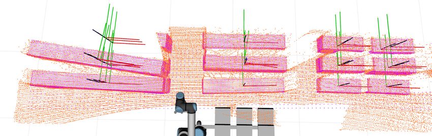
likely not be graspable using our magnetic gripper, so we can ignore these cases and filter them later.Figure 11: Precise alignment of individual bricks. Laser measurements are colored orange, model points are
shown in purple. Top: Initial solution found by the rough ICP stage. Bottom: Resulting brick poses. The
scan was captured during a competition run.
For correspondence information, we re-render the scene using the pose BT̃W,P obtained from rough alignment.
Here, we include the ground plane in the rendering, since we can use it to constrain the lowest layer of bricks.
We separate the resulting point cloud into individual brick clouds P Cbj .
We now minimize the objective
N M (j)
X X 1
Emulti = k(R(θj )pj,i + tj − qj,i )T nqj,i k2 , (2)
j=1 i=1
M (j)
where the optimized parameters θi and ti describe the yaw angle and translation of brick i, N is the
number of bricks, M (j) is the number of found point-to-point correspondences for brick j, pj,i ∈ P Cbj and
qj,i ∈ P Cs are corresponding points, and nq is the normal in point q. This is a point-to-plane ICP objective
with separate correspondences for each brick. Correspondences are filtered using thresholds λdot and λdist
for normal dot products and maximum point distances.
To keep the wall structure intact during optimization, we add additional cost terms for relationships between
bricks that touch each other, which punish deviations from their relative poses in the initialization:
bi
R
Ei,j = λr kR(θi ) B Rbi (R(θj ) B Rbj )−1 B Rbj RB − Ik2F , (3)
T B B −1 B bi
Ei,j = λt kt(T (θi , ti ) Tbi (T (θj , tj ) Tbj ) Tbj TB )k22 , (4)
where || · ||F denotes the matrix norm, and λr , λt are balancing factors. Note that these pairwise cost terms
have equal strength for all involved brick pairs.
As in the rough alignment phase, the parameters are optimized using Ceres using the same termination
criteria up to a maximum of 20 iterations. The optimization takes around 0.15 s on the onboard computer
for one iteration with 20 bricks. As an additional output, we compute a confidence parameter for each brick
as the ratio of found correspondences to expected visible points according to the rendered model. Figure 11
shows an exemplary result of the entire brick perception pipeline.
6.2 Heat Source Detection
The simulated fires in the ground level room of Challenge 3 are mounted inside acrylic glass enclosures, which
raises different challenges: Firstly, only a fraction of the infrared rays penetrates the walls, so the thermal
detection works only through the hole in the front which results in a very narrow window for detection.
Secondly, the LiDAR hardly ever perceives transparent acrylic glass, so determining the exact 3D position isanother challenge. To deal with the small detection window, we employ an arm sweeping motion and perform thresholding on the thermal images to check for heat sources. Assuming the thermal element has reached the nominal temperature and is observed at a nearly orthogonal angle through the hole, the bounding box of the thermal detection can be used to estimate the distance. We used an equivalent heat element for calibrating the measurements. Back projecting the detection’s center point with this distance results in a 3D position estimate of the heat source. 6.3 Laser Navigation We localize our UGV w.r.t. the building using LiDAR. In a test run, we collected data to generate a Multi- Resolution Surfel Map (MRSMap) of the arena with (Droeschel and Behnke, 2018). During localization, we register the current LiDAR point cloud against the map. Instead of estimating a correction transformation from the GPS-based field frame to the map frame, we calculate the offset transformation between the map’s field origin and the odometry frame without GPS. The wheel encoder odometry is reset each time at start-up, but is accurate enough to be used as initialization during incremental scan matching. The map is combined from two separately recorded segments, the first from the approach to the entrance and the second from a round trip inside the simulated kitchen. Both segments are mapped as before and then aligned. This allows to center the finer level of the multi-resolution map and thus yields a better representation where it is needed. While approaching the building, we use the outdoor map and switch to the indoor map before passing the doorway. 7 Evaluation We evaluated our UGV Bob during the MBZIRC 2020 Finals and in additional experiments in our lab. During the MBZIRC 2020 Finals, our UGV performed in five arena runs per challenge and an additional Grand Challenge run. We used the three rehearsal days to get familiar with the arena conditions and fixed Wi-Fi issues. We picked bricks in a semi-autonomous way and fine-tuned our perception pipeline for Challenge 2. We collected LiDAR measurements of the building and tested our thermal perception within the arena environment. Unfortunately, in the first Challenge 2 competition run we had issues with the gripper. We attempted over 15 times to pick up an orange brick with very promising perception results but were unsuccessful. We were unable to fix this problem since hardware changes were not allowed during the competition run. In the second competition run, we were able to autonomously pick and store a green brick successfully, but again scored zero points since our UGV was not able to drive accurately on the slope inside the arena to reach the wall building position. The wheel controller had an unnecessary power limit and was tuned for flat ground. We were able to fix these problems over night. Due to limited test time, we did not discover this problem earlier. Nevertheless, the points collected by our UAV were enough to secure an overall second place in Challenge 2. On the first Challenge 3 competition day, the UGV could unfortunately not compete due to software issues. During the second challenge run the autonomy worked well to the point, where the UGV tried to position the arm for scanning the first location for heat signatures. Because the manually configured approximate fire location was wrong (see Fig. 12 left), the arm collided with the target which triggered the emergency stop. While trying to maneuver the robot outside during reset, the not sufficiently tested motor controller malfunctioned and the robot drove into a cupboard. After resetting to the start zone, the faulty controller caused the robot to drive towards the arena boundary, even though localization and waypoints were correct. Near the end of the run, we switched to manual mode. With arm motions and a pump macro prepared in advance, the robot managed to spray 470 ml of water into the container just before the timeout.
Table 1: Build order optimization.
Method |B| dB [m] Runtime [s]
mean stddev mean stddev mean stddev
Optimal 5.0 0.91 3.36 0.97 7.5 29.0
Greedy 5.5 1.10 5.63 1.86 0.0 0.0
Computing the build order (B) using our optimization versus a greedy
approach over 1000 randomly generated blueprints. The path length to
reach all build positions is denoted as dB . |B| define the number of build
positions given the build order B.
After analyzing the collected data, we also found minor localization inaccuracies while entering the building
(see Fig. 12 left), due to proximity of inside and outside points in the map. After creating separate maps
and switching on driving inside, the localization performed accurately.
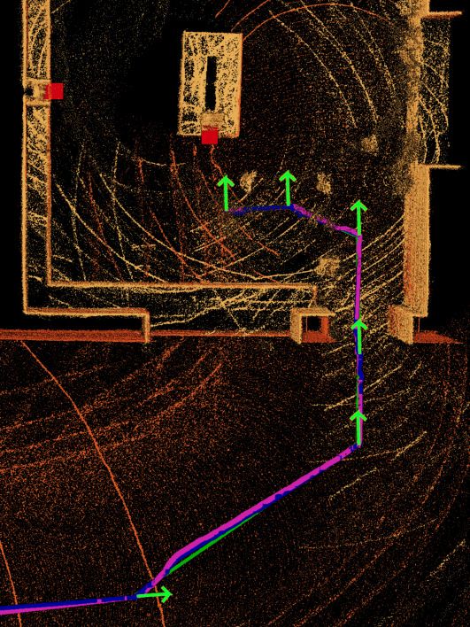
Figure 12: Navigation map and UGV trajectories on Trial Day 2 (left) with active Fire 2 and the Grand
Challenge run (right) with active Fire 1. The light green straight lines show the planned trajectory, where
each light green arrow denotes a waypoint with the direction indicating the robot’s heading. The other
lines are the actual driven trajectory according to localization, colored differently after each reset. Two red
rectangles predefine (using the recorded map of the building) the suspected fire locations to scan for heat
signatures.
In the final Grand Challenge our UGV had to perform both tasks in sequence. In order to maximize our
overall points, our team decided to assign Bob the Challenge 3 task first. The UGV successfully solved the
task autonomously. There was an issue with a disconnected tf-tree, which led to the state machine stopping
in front of the first fire. After a reset, the issue was solved and the UGV successfully performed as intended:
it stopped in front of the first location, scanned for the heat source, aimed and sprayed sufficient water to
achieve the full score. Fig. 12 right shows driven trajectories during the first and second attempt. The small
deviation after the first waypoint in both images was due to an edge on the uneven ground, otherwise the
overlap of planned- and driven trajectories demonstrates the high accuracy of our method. Due to some
resets caused by the UGV and the flying robots, only two minutes were left, which was not enough time to
score any points in Challenge 2. Overall, our team NimbRo scored the second place in the MBZIRC 2020
Grand Challenge finals.
After the competition, we evaluated the wall marker detection (see Section 6.1.2) on a dataset recorded
inside the arena during a rehearsal run. The robot was teleoperated through the arena, driving past the
marker. There is a gap of 45 seconds in the marker predictions after the spot marked with a green circle,25
180
20 160
Yellow Magenta
15 140
Time [s]
y [m]
120
10
100
5
80
0
20 25 30 35 40 45 50
x [m]
Figure 13: Marker detection during practice run. The robot was teleoperated through the arena, driving
past the marker. Bob’s trajectory is shown colored by time. Each detection is shown as a red square, with
an arrow from Bob’s position at detection time. The images on the left show an example scene captured at
the green circle including the yellow and magenta color mask output.
since Bob was not facing the marker while driving to the arena boundary. The outlier in the detected marker
position can be explained by the slope the robot was driving on. First, our localization using only wheel
odometry had problems when driving over the edges at the beginning and end of the slope. Second, we
assumed the arena would be placed on a flat area. The height increase relative to the robot starting pose led
to an imprecise projection of the estimated marker onto the expected ground plane. Nevertheless, the results
show that the marker detection worked reliably in the challenging lighting conditions with a distance of up
to 11 m between the robot and the marker. The standard deviation of the marker position relative to robot
starting location was 0.40 m (in the x direction of our arena frame) and 0.35 m (y direction). Ignoring the
outlier generated by the slope, the standard deviation drops to 0.3 m in both directions. Since we fixed the
motor controller to handle the slope before the Grand Challenge run, this would have been robust enough
to locate the wall marker during the competition.
In addition to the competition, we evaluated two sub-systems and a simplified Challenge 2 task in our lab
environment.
We compared our algorithm for optimizing the build order (see Section 5.1) with a greedy strategy. Using
the greedy strategy, we take the best local solution, i.e. given a set of already built bricks, we chose the next
build position such that the number of bricks the UGV able to build is maximal. Table 1 shows the results
of both approaches on 1,000 randomly generated blueprints. The optimization reduces the different build
positions needed from 5.5 to 5.0 on average and gives an even larger improvement regarding the distance
needed to be driven by 2.3 m on average. Performing the optimization takes on average 7.5 s, which is
feasible in our use case since it is performed just once before the competition run. Nevertheless, it is—as
expected—much slower than the greedy approach due to the exponential complexity.
In a second lab experiment, we evaluated the precision and repeatability of picking up bricks from a pile
(see Fig. 14). We placed four bricks in front of the robot in a similar way the piles in the competition
were arranged. The target place pose was on the left side of the robot on the floor. Each test consists of
scanning the piles, picking the brick with the highest confidence, and placing it at the target pose. We than
calculated the mean translation and rotation error compared to the ground truth pose, which was defined by
placing a perfectly center-grasped brick at the target location. Only a rough estimation of the pile location
was provided to the system. We repeated the test ten times for each brick type while changing the brickTable 2: End-to-end brick manipulation precision.
Brick Translation x [cm] Translation y [cm] Yaw [◦ ]
mean stddev mean stddev mean stddev
Red 1.52 0.36 1.49 0.37 1.26 0.80
Green 1.94 0.33 0.67 0.43 1.26 0.68
Blue 1.82 0.49 0.53 0.21 0.76 0.40
Orange 1.34 0.65 0.36 0.39 0.45 0.24
Placement error from perceiving, picking, and placing. Ten tests per color.
Table 3: Autonomous wall building test results.
Run Success Time [min] Reason of failure Component avg. Time [min]
1 yes 10:40 High-level planner 0:03
2 yes 10:45 Pile perception 1:05
3 no - storage collision Pile locomotion 0:50
4 no - arm protective stop Pile manipulation 5:00
5 yes 11:06 Wall perception 0:30
6 yes 11:01 Wall locomotion 0:17
Wall manipulation 3:06
Full system 10:53
Six autonomous test runs evaluating the whole system. 11 bricks had to be picked, transported and placed.
horizontal positions by up to 5 cm and the rotation by up to 10◦ around the vertical axis. Table 2 shows the
mean results per brick for ten tests each. The resulting mean error could be further decreased by investing
more time calibrating the whole system; nevertheless, it is sufficient to place the bricks reliably into the
storage system. The very low standard deviation in both rotation and translation shows that our perception
and grasping pipeline has a high repeatability and is very robust.
In addition to the sub-system evaluations, we tested our whole pipeline with a simplified Challenge 2 task
(see Fig. 15). The lab experiments were performed on the smaller Mario platform (UGV winner of MBZIRC
2017) with a down-scaled version of the storage system. Mario has been equipped with exactly the same
drive system and arm as Bob. The main difference between both robots is their footprint (1.9×1.4 m versus
1.08×0.78 m). Thus, Mario is only capable to carry a single storage compartment. We modified the high-
level planner to support multiple bricks of different types in the smaller storage system. The remaining
components are the same compared to Bob. To test the full pipeline, we placed three blue, four green, and
y
x
Figure 14: UGV pick and place robustness. Ground truth place pose (black) and ten test results for each
brick type.four red bricks in piles similar to the competition conditions. The visual marker for the desired wall pose was placed approx. 4 m apart from the pile location. Six evaluation runs were performed, each consisting of autonomous loading, transporting, and placing 11 bricks. Only rough pile and wall locations were provided to the robot. The results can be seen in Table 3. Four out of six runs were fully successful. The UGV needed around 11 minutes to solve the task. As reported in Table 3, the manipulation actions consume most of the time. In contrast, locomotion and planning time is negligible. During Run 3, the robot decided to load the bricks in a different order than expected. Due to the different arrangement of the storage system on the smaller Mario robot, the arm collided with the storage system. After fixing this issue, the UR10e arm stopped during Run 4 while moving a brick due to communication problems with the controlling PC. The implemented arm recovery strategy worked as expected but the run failed since the robot lost the brick during the stop and needed all bricks to fully complete the task. The UGV performed as expected in the remaining four runs resulting in similar execution times, which shows the robustness of the system. Two example walls built fully autonomously can be seen in Fig. 16. Figure 15: Autonomous wall building. Bob is loading bricks (left) and building the predefined wall (right). Figure 16: Experiment: Two example results building a predefined wall structure fully autonomously. Tiny differences in the brick alignment can be seen at the green bricks. 8 Lessons Learned and Conclusion We take the opportunity to identify key strengths and weaknesses of our system and development approach. We also want to identify aspects of the competition that could be improved to increase scientific benefit in the future. Regarding our system, we saw very little problems with our hardware design itself. For Challenge 2, reducing the number of required trips between pile and wall, Bob could have scored a large number of points in little time. After solving initial problems with our magnets, it could manipulate even the large orange bricks. While the large distance between pile and wall is challenging, our system is not reliant on precise global navigation. Instead we react to local pose estimates for pile, bricks, and wall, so that inaccuracies cannot accumulate. In Challenge 3, the distance between the robot start and target location was much smaller. In addition, we used global LiDAR localization which ensured precise locomotion. However, the sloped terrain posed unexpected problems for our drive system and controller.
The biggest issue shortly before and during the competition was unavailable testing time in comparison
to the complexity of the developed system. Due to resource conflicts when building all robots needed for
the MBZIRC 2020 competition, hardware and software component development and testing in our lab was
executed on the modified Mario robot which was slightly different from the Bob robot used at the competition.
Robust solutions require full-stack testing under competition constraints. Since we postponed many design
decisions until the rules were settled, our complex design could not be tested fully before the event. In
hindsight, simpler designs with fewer components, which would have required less thorough testing, could
have been more successful in the short available time frame.

Notable to all teams, the MBZIRC 2020 suffered from general low team performance. We think there are
underlying systematic causes for this low team performance. From the perspective of participants, we think
the frequent and late changes of the rules have certainly contributed to this situation. A pre-competition
event such as the Testbed in the DARPA Robotics Challenge can help to identify key issues with rules and
material early in the competition time-line. Also, MBZIRC 2020 required participants to address seven
completely different tasks if they wanted to gain maximum points, ideally with custom-tailored robots for
each task. Maybe focusing on general usability by constraining the number of allowed platforms per team
could lower the required effort and allow smaller teams to compete as well.

On the positive side, we noticed that having back-up strategies to address the task on a lower level of
autonomy is highly useful. Such assistance functions increase flexibility and can make the difference between
not solving the task at all and solving it partially—as demonstrated during our Challenge 3 run which scored
manual points. Also reducing high-level control to a bare minimum, instead of a universal strategy, makes
the systems easier to test and reduces potential errors.

In the future, we will increase our focus on testing the developed components in competition-related scenarios
to increase the robustness of the system and to not depend on extensive testing on site during the rehearsal
days. Regarding the locomotion system, we would like to increase the locomotion precision even further by
incorporating IMU and—if available—GPS data.

In this article, we presented our UGV Bob developed for two challenges at the MBZIRC 2020 competition.
The robot successfully delivered autonomously the maximum amount of water into the fire in the Grand
Challenge. Even though this robot was not able to score any points in Challenge 2 during the competition,
after analyzing and fixing the issues, our experiments show that the system functions reliably. The perception
and manipulation modules worked reliably and accurately. Our developed hard- and software systems for
the MBZIRC 2017 competition together with the gained experience has proven to be useful for developing
related systems. Similarly, the knowledge gained and components developed in MBZIRC 2020 will also prove
useful in future applications.

Acknowledgments

We would like to thank all members of our team NimbRo for their support before and during the competition.
This work has been supported by a grant of the Mohamed Bin Zayed International Robotics Challenge
(MBZIRC).

References

Agarwal, S., Mierle, K., and Others (2010). Ceres solver. http://ceres-solver.org.
Bilberg, C. P., Witting, C. A., Andersen, N. A., and Ravn, O. (2019). Force-based perception and manipu-
    lation, the DTU team competing in MBZIRC 2017. Journal of Field Robotics, 36(3):517–530.
Delmerico, J., Mintchev, S., Giusti, A., Gromov, B., Melo, K., Horvat, T., Cadena, C., Hutter, M., Ijspeert,
    A., Floreano, D., et al. (2019). The current state and future outlook of rescue robotics. J. of Field
    Robotics, 36(7):1171–1191.
Dörfler, K., Sandy, T., Giftthaler, M., Gramazio, F., Kohler, M., and Buchli, J. (2016). Mobile robotic
brickwork. In Robotic Fabrication in Architecture, Art and Design 2016, pages 204–217. Springer.
Droeschel, D. and Behnke, S. (2018). Efficient continuous-time SLAM for 3D lidar-based online mapping.
In Proc. of IEEE Int. Conf. on Robotics and Automation (ICRA).
Ghamry, K. A., Kamel, M. A., and Zhang, Y. (2016). Cooperative forest monitoring and fire detection
using a team of UAVs-UGVs. In Proc. of Int. Conf. on Unmanned Aircraft Systems (ICUAS), pages
1206–1211. IEEE.
Hashimoto, K., Kimura, S., Sakai, N., Hamamoto, S., Koizumi, A., Sun, X., Matsuzawa, T., Teramachi, T.,
Yoshida, Y., Imai, A., Kumagai, K., Matsubara, T., Yamaguchi, K., Ma, G., and Takanishi, A. (2017).
WAREC-1 - A four-limbed robot having high locomotion ability with versatility in locomotion styles.
In IEEE International Symposium on Safety, Security and Rescue Robotics (SSRR), pages 172–178.
Howe and Howe Technologies (2020). Thermite fire fighting robot. www.roboticfirefighters.com, accessed
2020-09-30.
Keating, S. J., Leland, J. C., Cai, L., and Oxman, N. (2017). Toward site-specific and self-sufficient robotic
fabrication on architectural scales. Science Robotics, 2(5).
Klamt, T., Kamedula, M., Karaoguz, H., Kashiri, N., Laurenzi, A., Lenz, C., Leonardis, D. D., Hoffman,
E. M., Muratore, L., Pavlichenko, D., Porcini, F., Rodriguez, D., Ren, Z., Schilling, F., Schwarz,
M., Solazzi, M., Felsberg, M., Frisoli, A., Gustmann, M., Jensfelt, P., Nordberg, K., Rossmann, J.,
Baccelliere, L., Süss, U., Tsagarakis, N. G., Behnke, S., Chen, X., Chiaradia, D., Cichon, T., Gabardi,
M., Guria, P., and Holmquist, K. (2019). Flexible disaster response of tomorrow: Final presentation
and evaluation of the CENTAURO system. IEEE Robotics and Automation Magazine, 26(4):59–72.
Krotkov, E., Hackett, D., Jackel, L., Perschbacher, M., Pippine, J., Strauss, J., Pratt, G., and Orlowski, C.
(2017). The DARPA robotics challenge finals: results and perspectives. Jnl. Field Rob., 34(2).
Krueger, V., Chazoule, A., Crosby, M., Lasnier, A., Pedersen, M. R., Rovida, F., Nalpantidis, L., Petrick,
R., Toscano, C., and Veiga, G. (2016). A vertical and cyber–physical integration of cognitive robots in
manufacturing. Proceedings of the IEEE, 104(5):1114–1127.
Krug, R., Stoyanov, T., Tincani, V., Andreasson, H., Mosberger, R., Fantoni, G., and Lilienthal, A. J.
(2016). The next step in robot commissioning: Autonomous picking and palletizing. IEEE Robotics and
Automation Letters, 1(1):546–553.
Lenz, C., Schwarz, M., Rochow, A., Razlaw, J., Arul Periyasamy, S., Schreiber, M., and Behnke, S. (2020).
Autonomous wall building with a UGV-UAV team at MBZIRC 2020. International Symposium on
Safety, Security, and Rescue Robotics (SSRR).
Low, K.-L. (2004). Linear least-squares optimization for point-to-plane ICP surface registration. Technical
Report.
LUF GmbH (2020). LUF fire fighting robot. www.luf60.at, accessed 2020-09-30.
Quigley, M., Conley, K., Gerkey, B. P., Faust, J., Foote, T., Leibs, J., Wheeler, R., and Ng, A. Y. (2009).
ROS: An open-source robot operating system. In Proceedings of the ICRA Workshop on Open Source
Software.
Raveendran, R., Ariram, S., Tikanmäki, A., and Röning, J. (2020). Development of task-oriented ROS-based
autonomous UGV with 3D object detection. In IEEE International Conference on Real-time Computing
and Robotics (RCAR), pages 427–432.
Schwarz, M. and Behnke, S. (2020). Stillleben: Realistic scene synthesis for deep learning in robotics. In
Proc. of IEEE Int. Conf. on Robotics and Automation (ICRA).You can also read