DYWIDAG Multistrand Stay Cable Systems - DSI Civil
←
→
Page content transcription
If your browser does not render page correctly, please read the page content below
DYWIDAG Multistrand Stay Cable Systems
2
Contents

History�������������������������������������������������������������������������������������������������������������������������������������������������������������������������������������������������� 4
DYNA Grip® Stay Cable System����������������������������������������������������������������������������������������������������������������������������������������������������������� 6
  High Fatigue Performance��������������������������������������������������������������������������������������������������������������������������������������������������������������� 6
  Durability and high-quality Corrosion Protection����������������������������������������������������������������������������������������������������������������������������� 7
  Replaceability of Strands����������������������������������������������������������������������������������������������������������������������������������������������������������������� 7
  Fast Construction Cycles����������������������������������������������������������������������������������������������������������������������������������������������������������������� 7
  Drawing�������������������������������������������������������������������������������������������������������������������������������������������������������������������������������������������� 8
DYNA Grip® Stay Cable System – Optional Solutions������������������������������������������������������������������������������������������������������������������������ 10
  Vandalism Protection & Guide Deviator����������������������������������������������������������������������������������������������������������������������������������������� 10
  Cable Hardening���������������������������������������������������������������������������������������������������������������������������������������������������������������������������� 11
  Fire Protection�������������������������������������������������������������������������������������������������������������������������������������������������������������������������������� 12
  Cable De-icing������������������������������������������������������������������������������������������������������������������������������������������������������������������������������� 13
  Clevis Anchorage��������������������������������������������������������������������������������������������������������������������������������������������������������������������������� 14
DYNA® Link Anchor Box System�������������������������������������������������������������������������������������������������������������������������������������������������������� 16
  Advantages to Conventional Pylon Solutions�������������������������������������������������������������������������������������������������������������������������������� 16
  Advantages in Comparison to Conventional Saddle Solutions����������������������������������������������������������������������������������������������������� 17
  Stay Cable Installation������������������������������������������������������������������������������������������������������������������������������������������������������������������� 19
Saddle Solution���������������������������������������������������������������������������������������������������������������������������������������������������������������������������������� 20
  Saddle with Individual Tubes��������������������������������������������������������������������������������������������������������������������������������������������������������� 20
Fully Grouted Solutions���������������������������������������������������������������������������������������������������������������������������������������������������������������������� 22
   DYNA Bond® Anchorage���������������������������������������������������������������������������������������������������������������������������������������������������������������� 22
   Saddle with Anchor Groove and Pin���������������������������������������������������������������������������������������������������������������������������������������������� 23
Strand and Wedge������������������������������������������������������������������������������������������������������������������������������������������������������������������������������ 24
   Epoxy Coated Strands������������������������������������������������������������������������������������������������������������������������������������������������������������������� 24
   Outer Stay Pipe������������������������������������������������������������������������������������������������������������������������������������������������������������������������������ 25
Cable Damping����������������������������������������������������������������������������������������������������������������������������������������������������������������������������������� 26
  Excitation Causes�������������������������������������������������������������������������������������������������������������������������������������������������������������������������� 27
  Damper Design������������������������������������������������������������������������������������������������������������������������������������������������������������������������������ 28
Full Size Testing���������������������������������������������������������������������������������������������������������������������������������������������������������������������������������� 30
   Standard Fatigue and Tensile Testing�������������������������������������������������������������������������������������������������������������������������������������������� 30
   Fatigue and Tensile Testing with higher load level and additional Transverse Deflection��������������������������������������������������������������� 30
   Fatigue and Tensile Testing with additional Transverse Deflection (Setra)������������������������������������������������������������������������������������� 31
   Increased Load Cycle Testing – 10 Million Cycles������������������������������������������������������������������������������������������������������������������������� 31
   Monostrand Fatigue Testing under Reversed Cyclic Flexural Loading������������������������������������������������������������������������������������������ 32
   Leak Tightness Test����������������������������������������������������������������������������������������������������������������������������������������������������������������������� 33
Cable Installation�������������������������������������������������������������������������������������������������������������������������������������������������������������������������������� 34
Stressing��������������������������������������������������������������������������������������������������������������������������������������������������������������������������������������������� 36
   ConTen Stressing��������������������������������������������������������������������������������������������������������������������������������������������������������������������������� 36
DYNA Force® Elasto-Magnetic Sensor����������������������������������������������������������������������������������������������������������������������������������������������� 38
  Functional Principle����������������������������������������������������������������������������������������������������������������������������������������������������������������������� 38
  System Components��������������������������������������������������������������������������������������������������������������������������������������������������������������������� 38
  System Advantages in Comparison to other Measuring Systems������������������������������������������������������������������������������������������������� 38
  Quality Assurance�������������������������������������������������������������������������������������������������������������������������������������������������������������������������� 39
  Practical Applications�������������������������������������������������������������������������������������������������������������������������������������������������������������������� 39
Cable Inspection�������������������������������������������������������������������������������������������������������������������������������������������������������������������������������� 40
  Visual Inspection���������������������������������������������������������������������������������������������������������������������������������������������������������������������������� 40
  Vibration Measurement������������������������������������������������������������������������������������������������������������������������������������������������������������������ 41
  Magnetic Flux Leakage Inspection������������������������������������������������������������������������������������������������������������������������������������������������ 41
References����������������������������������������������������������������������������������������������������������������������������������������������������������������������������������������� 42
  Stay Cable References������������������������������������������������������������������������������������������������������������������������������������������������������������������ 42
  Extradosed Bridges����������������������������������������������������������������������������������������������������������������������������������������������������������������������� 46
  Arch Bridges���������������������������������������������������������������������������������������������������������������������������������������������������������������������������������� 48
  Special Applications���������������������������������������������������������������������������������������������������������������������������������������������������������������������� 49

                                                                                                                                                                                                      3
History
DYWIDAG-Systems International (DSI) is a globally leading system supplier of innovative technologies for the construction industry.
Tradition Research & Development Certifications and
International Organizations
The long tradition of DSI reaches back Continued investments in Research &
as far as 1865 – the founding year of the Development and the resulting patent International organizations, trade
German construction firm, Dyckerhoff applications sustainably strengthen associations and standards committees
& Widmann AG (DYWIDAG). DSI was the know-how available within the are becoming more important in times
founded in the year 1979 to market DSI Construction Group. By offering in which products and services seem
DYWIDAG Systems and technical know- innovative solutions in accordance with more and more interchangeable.
how around the world and to develop superior quality standards, we fulfill the Organizations and trade associations
innovative systems resulting from its constantly changing requirements of our are cross-linked on a global basis and
own R&D activities. target markets. It is our declared aim to promote the exchange of technology
always be one step ahead. and know-how across borders. We are
DSI Technology an active member in many International
Client Orientation Organizations to drive technical
In more than 50 countries and at 15 developments. In April 2016, DSI
regional manufacturing sites, DSI The needs and requirements of clients received a general technical approval for
Construction develops, produces and business partners are always of DYNA Grip® Multistrand Stay Cables for
and supplies high quality systems paramount importance. Our company Stay Cable Bridges. It is the world’s first
such as DYWIDAG Post-Tensioning is characterized by reliability, trust and approval to regulate Multistrand Stay
Systems, Geotechnical Systems and cooperation based on partnership. Cable Systems.
“Concrete Accessories”. In accordance We offer our clients the advantages of
with our slogan “Local Presence an international system supplier with
– Global Competence”, more than a product range that is tailored to suit
1,400 specialized and experienced individual requirements.
DSI employees ensure that DSI’s
(German Institute for Civil Engineering)
technologies and know-how are Approval Office for Construction Products and
Construction Methods
ears of Servi
Testing Office for Structural Engineering
available around the world. DSI offers
A statutory body commonly sponsored by the
0 Y
German national government and the German
5 ce General Construction Lander
Member of the EOTA, UEAtc and WFTAO
quality on all levels – quality that is 1 Supervisory Authority
Approval
Date: Reference No.:
April 19, 2016 I 30-1.14.7-105/15
characterized by creativity, reliability and
profitability. Approval No.:
Z-14.7-759
Period of validity
from: April 19, 2016
to: April 19, 2021
Applicant:
Comprehensive Services
DYWIDAG-Systems
International GmbH
Destouchesstrasse 68
80796 München
Subject of approval:
Our comprehensive services include
®
DYWIDAG - Multistrand Stay Cable DYNA Grip
the conception, design, planning and The above-mentioned subject of approval is hereby granted a general construction supervisory
authority approval.
This general construction supervisory authority approval comprises 15 pages and 23 appended
installation of its systems as well sheets.
as quality management and on site Important Notice
This general construction supervisory authority approval is the
supervision. translation of a document originally prepared in the German language
which has not been verified and officially authorized by the “Deutsches
Institut für Bautechnik“ (German Institute for Civil Engineering). In case
of doubt in respect to the wording and interpretation of this approval,
the original German version of this document shall prevail exclusively.
Therefore, no liability is assumed for translation errors or inaccuracies.
DIBt I Kolonnenstrasse 30 B I D – 10829 Berlin I Phone:+49 30 78730–0 I Fax:+49 30 78730–320 I E-mail: dibt@dibt.de I
www.dibt.de
1994: Odawara Blueway Bridge, Odawara, Japan
4
History
Milestones
DYWIDAG Post-Tensioning Systems and which is known as the first extradosed
Stay Cable Systems are world renowned bridge in the world – as well as for Kap
for reliability and performance; they are Shui Mun Bridge (Hongkong) in 1995
perfectly suitable for all applications are two outstanding milestones in DSI’s
in post-tensioned construction. They stay cable history.
embrace the whole spectrum from
bridge construction and buildings to civil Established in 2000 and still used
applications – both above and below today, the DYNA Grip® System already
ground. took into account the requirements for
modern cable systems at the turn of the
In addition to traditional post-tensioning millennium.
systems with bars, DSI offers a
complete product line in strand post- Our stay cable systems have always
tensioning (bonded, unbonded and combined the highest safety and
external) as well as stay-cable systems reliability standards with excellent
to fulfill the changing requirements in economical efficiency in their research
the industry today and tomorrow. and development.
As a further developement of the Dependable corrosion protection
first cable stayed bridges in the 60’s methods, damper design, fire protection,
and 70’s of the last century, new vibration measurements and the recently
systems were introduced into the developed DYNA Force® monitoring
market considering new materials and system significantly contribute to the
increasing requirements on modern longevity of modern construction and
infrastructures. The application of DSI’s cable hardening for mitigating multiple
stay cable system for the Odawara threat scenarions (vandalism, fire, blasts
Blueway Bridge (Japan) in 1994 – etc.).
2000: Victoria Bridge, Rosario, Argentina 1972: 2. Main Bridge, Hoechst Chemicals,
First DYNA Grip® Stay Cable Bridge Frankfurt, Germany
1995: Kap Shui Mun Bridge, Hongkong, China
DYNA Bond® Stay Cable Bridge with 176 cables
5
DYNA Grip® Stay Cable System

                                             Leak Tightness
                                             Gap between threads is filled with
                                             corrosion protection compound for
                                             improved tightness

                        Replaceability
                        Exchange of single strands including
                        PE-coating through anchorage → no
                        interruption of traffic

                                                                                                    Excellent Durability
                                                                                                    A watertight and adjustable sealing unit
                                                                                                    and strands with PE-sheathing up to the
                                                                                                    wedge meet highest demands. No devia-
                                                                                                    tion of strands in the wedge gripping zone

                                                                      High Fatigue Capacity
                                                                      Compliance with internatio-
                                                                      nal fib and PTI standards

The DYNA Grip® Stressing Anchorage          High Fatigue Performance
consists of an anchor block in which the
strands are anchored by high fatigue 3      The system has proven its excellent             ■■ Tests on single strands under reversed
part-wedges. A ring nut is threaded onto    performance and fulfills the                       cyclic flexural loading with 45% and
the anchor block to transmit the cable      requirements of fib Bulletin 30 as well as         60% GUTS, 2 million load cycles
force into the structure via the bearing    PTI & Setra requirements for fatigue and           with anchorages inclined by 3.0° and
plate. A steel pipe which incorporates      tensile strength:                                  additional angular deviation between
bending and sealing provisions for the      ■■ Multiple full size tests on cable sizes         ± 10mrad and ± 35mrad
strands is part of the anchor block.           from 7 to 156 strands
A non-adjustable anchorage with the                                                         The leak tightness of the anchorage
                                            ■■ The system has been successfully
same provisions for bending and sealing                                                     area has been demonstrated for the
of the strands can be placed at the            tested in standard tests with a stress
                                                                                            complete system and even meets
dead-end side.                                 range of up to 200MPa at an upper
                                                                                            stringent fib and Setra requirements
                                               stress limit of 45% GUTS and at
                                                                                            with:
                                               2 million load cycles with anchorages
                                               inclined by 0.6°. In addition, full          ■■ Up to 3m water head
                                               size tests have been performed               ■■ Several load cycles in the longitudinal
                                               successfully with an upper load of up           and transverse direction
                                               to 60% GUTS, up to 10 million load           ■■ Temperature cycling 20–70°C
                                               cycles and a stress range of up to
                                               250MPa

  6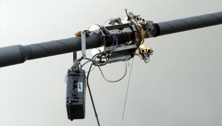
DYNA Grip® Stay Cable System
Free Length
Strands additionally
protected by UV-re-
sistant stay pipe.
Protection against Impact Outer helical fillet for
Usually used for vanda- reducing wind-rain
lism protection. Can also induced vibrations
be upgraded to a cable
hardening system resisting
fire and other multiple
threat scenarios
(blasts, cutting etc.)
Compaction Clamp
With straight guidance and smooth
inner radius for optimized cable
bending and minimized transverse
pressure. Also serves as supporting
structure in case a guide deviator or
damper is installed
Durability and high-quality Corrosion Protection
Strands are guided into the anchorage The anchorages have been designed Free length:
by an elaborate system that ensures for threading the strands including their ■■ The strands are protected by a multi-
both leak tightness and smooth PE-sheathing through the anchorage: layer system of galvanized wires and
deviation: ■■ Dismantling of the strand’s PE- are tightly sheathed by HDPE. A wax
■■ Compressible sealing plates ensure sheathing is minimized to what is filling is used for the interstices in
water and even vacuum tightness absolutely necessary. between.
■■ The correct function can be checked ■■ The factory applied corrosion ■■ An outer stay pipe made of UV-
and even adjusted during inspection protection of the strands continues resistant HDPE additionally protects
■■ Bending stresses are minimized by directly up to the wedges. the strands and minimizes rain-wind
a filter that arranges a straight-line ■■ Significant reduction of the length induced vibrations with an outer
entering into the wedge gripping area of anchorage area where interstices helical fillet that provides a low drag
are filled with corrosion protection coefficient.
■■ A cap including filler material for the
protection of individual strands is compound. Both high durability and
placed in front cost savings in terms of additional
filling material are guaranteed.
■■ Corrosion protection resists corrosivity
class C5 in accordance with
ISO 12944
Replaceability of Strands Fast Construction Cycles
As the PE-coating is pulled directly ■■ Lightweight equipment for strand ■■ No exact dismantling of the strand’s
through the anchorage, an exchange of installation and stressing operations is outer sheathing is necessary. In
strands is possible at any time during provided by DSI. case of stressing actions that are
the service life of the bridge without the ■■ The use of tower cranes or other additionally required, the strand
need for renewing or replacing any other lifting equipment can be limited to a sheathing is compressed by small
cable components. minimum. tubes in front of the wedges while the
■■ Strand exchange is performed directly strand is pulled through and elongated
■■ Non-protruding recess pipes at the
at the anchorages by the jack.
pylon → no additional formwork
■■ There is no need for moving the adjustment is required. ■■ A compaction clamp, installed after
cable’s outer stay pipe for accessing stressing on the strand bundle, keeps
the strand bundle either at the deck or the strand in a compact hexagonal
outside the pylon – no disruptions to pattern.
traffic.
7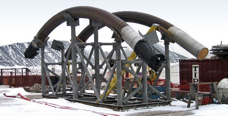
DYNA Grip® Stay Cable System

Drawing

                                    Ring Nut

                  Compression Tubes                 Sealing Plates

                           Wedges                       Spacer                                 Strands
                                                                                                                                     Compaction Clamp

                                                           Compression Plate

                                                                                                                                                                ∅P
oA
         ∅R

                                                                   ∅T

                                                                                                                                                       HDPE Sheathing
                                          D    C
     Cap        Anchor Block                             Bearing Plate               Recess Pipe                         Vandalism Protection Pipe

                                          B
                                                                            min LS

DYNA Grip® Anchorage – Technical Data
(forces calculated with strands 0.62" St 1660/1860)

                                  Cable type *                                        DG-P4               DG-P7              DG-P12          DG-P19             DG-P31
                                  No. of strands                                          4                  7                  12               19                31

                         Forces [kN] **
                         Ultimate load at 100% GUTS                                    1,116               1,953              3,348            5,301             8,649
                   Service load at 50% GUTS for stay cables                             558                 977               1,674            2,651             4,325
               Service load at 60% GUTS for extradosed tendons                          670                1,172              2,009            3,181             5,189

                       Dimensions [mm]
                         Bearing plate ***                            ¨A                190                 250                300              370               460
                         Bearing plate ***                              C                20                  25                 30               35                40
                      Bearing plate opening                           ∅T                112                 145                183              219               267
                            Thread ****                                 B               160                 170                200              220               230
                               Ring nut                                 D                50                  50                 90              110               120
                               Ring nut                               ∅R                150                 210                244              287               350
                           Dead anchor                                  E                50                  90                120              120               135
                           Dead anchor                                ∅F                150                 190                215              261               324
          Distance of compaction clamp, stressing end                min LS             520                 650                880             1,080             1,350
              Distance of compaction clamp, dead end                 min LD             430                 540                770              970              1,240
                         HDPE sheathing                               ∅P                 63                  90                110              125               160
                       HDPE transition tube                           ∅S                110                 140                200              225               250
*	 larger sizes on special request
**	 local design guidelines must be taken into account
*** 	 dimensions correspond to concrete strength ≥ 35MPa (cylinder) at 45% GUTS according to PTI anchorage zone design
**** 	 standard length, changeable on special request
Subject to modification

     8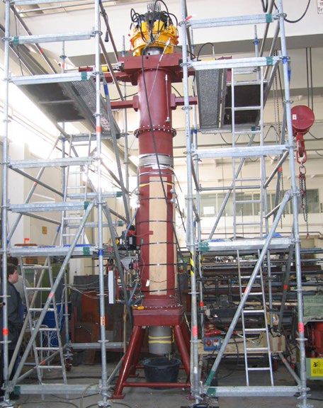
DYNA Grip® Stay Cable System

       HDPE Sleeve                                                              Dead Anchor
           ∅S

                                                                                                                oA
                                                                                                     ∅F
                                                                      ∅T
                                                                                     C        E

                                                        min LD

DG-P37          DG-P43       DG-P55   DG-P61   DG-P73      DG-P85     DG-P91          DG-P109     DG-P127
  37                  43       55       61       73              85        91             109       127

10,323           11,997      15,345   17,019   20,367       23,715    25,389             30,411    35,433
 5,162               5,999    7,673    8,510   10,184       11,858    12,695             15,206    17,717
 6,194               7,198    9,207   10,211   12,220       14,229    15,233             18,247    21,260

 500                 600      600      640      715          780       780                855       910
  45                  55       60       65       70              75        80             85        90
 293                 329      341      371      403          429       455                479       531
 240                 250      270      275      290          300       310                340       350
 130                 140      160      165      180          190       200                230       240
 378                 420      440      480      536          554       600                636       700
 135                 150      170      170      185          190       195                210       220
 354                 398      420      450      490          522       550                586       645
 1,500               1,690    1,750    1,920    2,070       2,170      2,340             3,020     3,390
 1,390               1,580    1,640    1,810    1,960       2,050      2,230             2,910     3,280
 180                 180      200      225      250          280       280                315       315
 250                 315      315      315      355          355       355                450       450

                                                                                                            9
DYNA Grip® Stay Cable System – Optional Solutions

Vandalism Protection & Guide Deviator
The DYNA Grip® Stay Cable System can be easily adjusted or upgraded if required:
■■ The length of the vandalism protection ■■ On special request, guide deviators       ■■ DSI has patented (EP2729621 B1;
   pipe can be adjusted to project           can be provided both at the deck and         US9009899 B2) an eccentric flange
   specific requirements to achieve any      at the pylon to:                             connection between the recess pipe
   requested height above the bridge         ■■ reduce cable bending at the               and the housing for the guide deviator.
   deck level. It can be made of 2 long         anchorages                                The eccentric flange connection
   parts or customized for retrofitting      ■■ decrease cable vibrations                 ensures that eccentricities caused by
   purposes.                                                                              wrong installation angles of the recess
                                                                                          pipe can be compensated.

                                                                                    HDPE Sheathing

                                               Vandalism Protection Pipe

                              Guide Deviator

Eccentric Flange Connection

                                                                                              Deck Superstructure

 10
DYNA Grip® Stay Cable System – Optional Solutions
Cable Hardening
DSI’s cable hardening system has been developed to protect the stay cables effectively against multiple threat scenarios for all stay
cable sizes.
■■ Any kind of mitigation level in terms of ■■ Numerical simulation and physical ■■ Therefore, DSI’s Cable Hardening
specific customized threat scenarios testing is carried out using expertise system is designed according but
and the required strength of the from Fraunhofer Institute for High not limited to the typical and notable
protection system can be taken into Speed Dynamics (Ernst-Mach- threats as shown in table below
consideration. Institute) ■■ Adaptable for bridge retrofitting
■■ Highly effective protection material ■■ Validation of different scenarios with applications using half-shell
can be easily adjusted to requirements specific threats following bridge technology
and threats security guidelines (e.g. AASHTO)
Cable Hardening shows advantageous performance characteristics:
■■ Eases installation and is adjustable to ■■ Incorporates adjacent functional cable ■■ Allows easy inspection and
different bridge construction methods units like dampers either internally or maintenance of the protection system
■■ Can be adjusted to any kind of bridge externally itself but also the stay cable system in
construction layout within anchorage general
and transition zones
Cable Hardening Threat Resistance
Threat Type Available
Fire Hydrocarbon Fire Yes
HEIED Yes
Explosive Device
VBIED Yes
Thermal Cutting Yes
Non Explosive Device Mechanical Cutting Yes
Exothermic Lance Yes
Exothermic Lance
Outer Pipe
Highly effective Protection Material
Inner Pipe
Strand Bundle
11DYNA Grip® Stay Cable System – Optional Solutions
Fire Protection
Lightning, a car accident or other
external incidents may cause fire on
a bridge. In that case, the main parts
of the stay cable system need to be
protected against damage.
HDPE Sheathing
Fire Protection Mat
Strand Bundle
Fire Protection Mats for the Free Cable Length
DSI’s stay cable system fully complies ■■ Used for the free length of the stay
with PTI requirements for fire resistance cable
and has been verified using the load ■■ Covered by standard HDPE sheathing
capacity test at 300°C.
■■ Mats have a hydrophobic behavior to
avoid water absorption
Furthermore, special fire protection mats
resist a 1,100°C hydrocarbon fire for at ■■ Any other fire resistance period can be
least 30 minutes without the strands achieved easily by modifying the mat
heating up to above 300°C, thus fully thickness
complying with PTI requirements. ■■ Application in cable transition zone is
possible
PTI Load capacity test at 300°C
12DYNA Grip® Stay Cable System – Optional Solutions
Fire Protection
Anchorage Area
■■ Steel parts in the anchorage area can ■■ Protection has been demonstrated ■■ Fire protection coating fulfills the
be coated with a special fire protection during laboratory tests highest requirements according to
coat that is intumescent under heat standard ISO 12944, corrosivity
impact and thus protects class C5
the steel parts
Anchorage Protection System
Bearing Plate
Cap
Intumescent Coating
Ring Nut
Anchor Block
Cable De-icing
Methods are available to reduce the risk eliminating the risk of harming the cable climatic conditions, DSI closely cooper-
of snow and ice accumulation falling structure. ates with globally recognized expertise
from stay cables and endangering traffic and testing facilities.
running on the bridge’s superstructure. In order to comply with client specific
Patented measurements are designed, needs in dependance of different
13DYNA Grip® Stay Cable System – Optional Solutions
Clevis Anchorage
■■ Architectural requirements for the Fatigue tests were carried out at The tests respected an inclination
design of stay cable bridges are the Technical University of Munich of 0.6° – even towards the inflexible
steadily increasing. Pylons often need in accordance with fib Bulletin 30 centerline – and an upper load of 0.45
to be as slim and elegant as possible. requirements. GUTS. They were carried out with a
■■ Solutions are needed in which the stay stress range of 200N/mm² at 2 million
cables are connected to the structure load cycles.
outside of the pylon if the space inside
the pylon is insufficient for common These dynamic tests, as well as the
stay cable anchorages that are subsequent static tensile tests, were
supported by bearing plates. performed with outstanding success.
■■ DSI developed the DYNA Grip® Clevis
The clevis anchorage is not only suitable
Anchorage for strand cable types
for stay cable bridges, but can also be
DG-P4 to DG-P61 as standard sizes
used for arch bridge hangers where
with additional types on request,
available space in the arch is too small
offering an economic alternative to
for aligning ordinarily fixed anchors.
conventional systems that have been
used so far.
■■ The complete strand cable can Gusset Plate
be easily pre-assembled on the
superstructure and is lifted into its final
position afterwards. Anchor Block
■■ DSI offers special tools for the
preassembly of the clevis as well as
the mounting of the pin into the clevis
hole.
■■ Restressing of individual strands
as well as the replacement of the
complete strand bundle is possible.
■■ This system also offers other
DYNA Grip® System advantages.
Compaction Clamp Pin and
Pin Retainer
Clevis
Flange Tube
HDPE Transition Tube
HDPE Sheathing
14DYNA Grip® Stay Cable System – Optional Solutions
Clevis Anchorage
Wedge Keeper Plate
Corrosion
Anchor Block Protection Compound
Sealing Plates Pin Retainer
Spacer Pin Clevis
ØA
HDPE Sheathing Compaction Clamp Compression Plate
ØS
ØP
F
HDPE Transition Tube, Clevis D C
ØE
Flange Tube Wedges
ØG
H B
DYNA Grip® Clevis Anchorage – Technical Data
(forces calculated with strands 0.62" St 1660/1860)
Cable type* DG-P 4 DG-P 7 DG-P 12 DG-P 19 DG-P 31 DG-P 37 DG-P 43 DG-P 55 DG-P 61
No. of strands 4 7 12 19 31 37 43 55 61
Forces [kN]**
Ultimate load at 100% GUTS 1,116 1,953 3,348 5,301 8,649 10,323 11,997 15,345 17,019
Service load at 50% GUTS
558 977 1,674 2,651 4,325 5,162 5,999 7,673 8,510
for stay cables
Service load at 60% GUTS
670 1,172 2,009 3,181 5,189 6,194 7,198 9,207 10,211
for extradosed tendons
Dimensions [mm]
Clevis ØA 150 200 246 290 351 390 432 463 493
Clevis length B 350 385 436 528 616 667 720 810 838
Clevis C 67 82 105 136 170 191 211 239 252
Gusset plate D 88 108 136 177 221 241 264 301 311
Pin ØE 52 67 85 115 138 150 170 195 202
Gusset plate F 52 63 90 100 125 140 160 175 195
Gusset plate hole ØG 54 69 87 117 140 152 172 197 204
Distance of
H 400 510 740 940 1,210 1,360 1,550 1,610 1,780
compaction clamp
HDPE sheathing ØP 63 90 110 125 160 180 200 200 225
HDPE transition tube, clevis ØS 110 140 200 225 250 315 315 315 355
* Bigger size on special request
** Load design guidelines have to be considered
15DYNA® Link Anchor Box System
The DYNA® Link Anchor Box System
is based on a conventional steel
structure in which stay cables are
anchored with standard DYNA Grip®
anchorages. The DYNA® Link curved
Anchor Box is economically designed
using conventional steel construction
standards to ensure capacity,
serviceability and excellent fatigue
characteristics. Differential forces are
transferred to the concrete by shear
studs in regular design, which are
welded to the outer surface of the
Anchor Box flanges.
Advantages in Comparison to Conventional Pylon Solutions
The DYNA® Link Anchor Box features ■■ When using DYNA® Link Anchor ■■ Total cost and construction time of the
many advantages in comparison to Boxes, pylon dimensions can be pylon can be reduced.
conventional pylon solutions in which significantly reduced by eliminating ■■ Easy and fast installation of box and
cables are anchored inside the pylon anchorages inside the pylon. This stay cable with minimum manpower
section: allows slender and aesthetical pylon during cable installation.
shapes.
■■ The horizontal load can be transferred
■■ The pylon does not need to be hollow directly through the DYNA® Link
to allow access for installing, stressing Anchor Box with reduced stresses
and servicing the anchorages. within the concrete.
DYNA® Link Anchor Box Accessible Steel Box
16DYNA® Link Anchor Box System
Advantages in Comparison to Conventional Saddle Solutions
The DYNA® Link Anchor Box features many advantages in comparison to conventional saddle solutions in which strands are
guided through the pylon:
DYNA® Link Conventional Saddle
Topic Description Conclusion
The use of conventional saddles results in equal strand numbers on
both sides of the tower for each cable. This outcome might not be the
most efficient or desirable from an economical and behavioral point of
view. This is evident for end spans that have a considerably larger stiff-
With the DYNA® Link Anchor Box, the stay
ness than adjacent main spans and particularly for cables anchored
cable assembly is flexible. Different cable
close to end supports.
Bridge Design sizes can be used, and the effective cable
length with a working point at the anchorage
There is also uncertainty on what is the effective cable length to be used
is clearly defined.
in the structural analysis. This uncertainty stems from the fact that a
certain length of the curved strands inside the saddle will be subjected
to varying axial strains. This effect may be significant for the shorter
cables of Extradosed bridges.
Slip in conventional saddles is prevented by friction between the strands
and the saddle. Current design recommendations (such as PTI recom-
mendations and fib Bulletin 30) require that the friction factor be derived
from tests on specimens representing the parameters of the actual sad-
By means of the DYNA® Link Anchor Box,
dles. These tests are conducted in the laboratory in dry and controlled
the full cable force can be reliably taken at
conditions. Due to possible contamination or condensation, the condi-
each side of the pylon. There is no limitation
tions in an actual saddle on site may be quite different from the test
by a friction factor and there are no uncer-
conditions. This creates uncertainty as to the actual friction factor avail-
tainties of friction at different climatic condi-
able to resist differential cable forces during the construction and ser-
Friction Factor and tions. Friction tests and additional slip limit
vice stages of the bridge.
Slip Limit State stage investigations within the structural
computation are not required.
Slip of strands inside a saddle must be completely avoided. This is an
additional limit state that must be investigated and verified by the bridge
DYNA® Link Anchor Boxes can even be used
designer. This limit state is not related to the strength of the cable com-
in seismic regions where friction type saddles
ponents, but depends on the friction between strand and saddle and
are not recommended.
the magnitude of the cable forces at both ends of the saddle. Additional
load cases and combinations may need to be investigated using
advanced analytical methods, to ensure that this limit state would not
be violated.
At the DYNA® Link Anchor Box, the strands
Due to the curvature of saddles, bending and transverse stresses are are not deviated along the saddle. Therefore,
Bending and transferred to the strands. The bending stresses will reduce the axial the fatigue performance and durability is not
Transverse strength of the strands. The transverse stresses may result in fretting compromised, and existing full size fatigue
Stresses effects between the strand wires or between the strands and the saddle and leak tightness tests of DYNA Grip® stay
that will result in reduced fatigue strength of the strands. cable tests can be used. Furthermore, there
are no limits in the respective saddle radii.
17DYNA® Link Anchor Box System
Advantages to Conventional Saddle Solutions
Topic Description Conclusion
The use of cable saddles results in doubling the man power and equip-
The DYNA® Link Anchor Box provides full
ment required for the installation and stressing of cables. In addition,
flexibility for the construction cycle, as cables
Bridge saddles require the pace of cantilever construction on both sides of the
may be installed alternately so that the over-
Construction tower to always be symmetrical before a cable may be installed. This
all construction time can be significantly
results in increased construction costs and inefficient utilization of
reduced.
resources.
Saddles do not allow the inspection of strands inside them. This may be
The durability of the DYNA® Link Anchor Box
critical because the strands are anchored by friction inside the saddle
is not compromised, as there are no strands
pipes and are subjected to multi-axial stresses and differential move-
which are deviated. Window opening at the
Cable Inspection ments due to live and dynamic loads.
DYNA® Link Anchor Box allows easy access
and Maintenance
for inspection and maintenance. It is even
These conditions may adversely impact the design life of the strands
possible to replace a complete strand bundle
and their corrosion protection system; and this uncertainty may not be
only on one side of the pylon.
acceptable to bridge owners.
18DYNA® Link Anchor Box System
Stay Cable Installation
Depending on the pylon dimensions and
cable layout, the DYNA® Link Anchor
Box may either be provided with a
lateral or a top access at the pylon
interface for stay cable installation.
Standard solutions for both options
have been designed for each cable type
using Finite-Element Analysis software
with the following design assumptions
which are based on SETRA:
All standard solutions can be adapted
easily to any project specific demand,
and thus, the actual pylon dimension,
cable angles as well as design loads will
be taken into account. Von Mises stresses of a DYNA® Link Anchor Box with lateral access
Lateral Installation opening for DYNA Grip® Stay Cable Anchorage Open top Installation opening for DYNA Grip® Stay Cable Anchorage
Type Load Level Deviation
ULS DESIGN LOAD 90 % GUTS + 25 mrad deviation angle
45 % resp. 60 % GUTS
SLS DESIGN LOAD + 25 mrad deviation angle
(stay cable resp. extradosed)
200 MPa at 45 % GUTS
FLS DESIGN LOAD + 10 mrad deviation
resp. 140 MPa at 60% GUTS
19Saddle Solution
Saddle with Individual Tubes
If strands need to be guided through the ■■ Individual strands can be replaced
pylon structure and a transfer of forces ■■ Differential forces are transferred by
by friction is required, DYWIDAG offers friction
a saddle in which the strands are guided
■■ Application of Epoxy coated strands
from one side of the pylon to the other:
and consequently:
■■ Strands are placed into a multitude of ■■ no peeling of strands’ sheathing
individual, curved recess tubes. The within the saddle necessary Centering Plate
interstices between the saddle tube ■■ no pressure; the coating is therefore
and the recess tubes are grouted not in danger of being harmed, which
■■ The saddle itself is embedded into can occur when using PE-sheathed
concrete strand
Solid Plate
20Saddle Solution
Interstices filled with Grout
Individual, curved Recess Pipes
Curved Saddle Pipe
21Fully Grouted Solutions
DYNA Bond® Anchorage
The DYNA Bond® Anchorage consists Additional Advantages
of a conical steel pipe (bond socket)
supporting a wedge plate in which the ■■ Minimized bending effects at the ■■ Easy fixation of external dampers
strands are anchored with high-fatigue anchorage by placing an elastomeric directly on the grouted stay pipe
3-part wedges. A ring nut is fitted on the bearing inside the recess tube ■■ A special patent protected sealing
threaded end of the bond socket and ■■ Reliable corrosion protection for the provision allows to grout the
distributes the cable force through a sensitive anchorage area, as all voids anchorage area only so that the free
bearing plate into the structure. in the anchorage zone are filled with a length remains without grout
stable and robust filler
■■ During the construction period – prior
■■ Enhanced fire resistance and
to grouting the bond socket – all the
protection against vandalism, impact
applied loads are supported directly
loads and blast effects
by the wedges.
■■ At the final state of construction, all
additional loads (live loads, vibrations
and earthquakes) are partly resisted
by both wedges and grouted bond
socket.
■■ DYNA Bond® Anchorages have an
excellent fatigue resistance because
the bond action in the bond socket
substantially reduces the magnitude of
the dynamic loads reaching the wedge
anchorage. Fatigue tests have proven
a stress range of up to 240N/mm2
at an upper load of 45% GUTS and
2 million load cycles.
Boot
Elastomeric Bearing
Ring Nut Strands
Spacer
Filling Material
Wedges HDPE
Sheathing
Recess Pipe
Bond Socket
Bearing Plate
Cap Wedge Plate
22Fully Grouted Solutions
Saddle with Anchor Groove and Pin
The saddle transfers differential forces via a shear nose with pin into the pylon concrete construction.
■■ Strands (without PE coating inside the ■■ An inner, curved saddle pipe is guided transferred via a shear nose (anchor
saddle) are guided in a curved tube through an outer recess pipe that is groove – pin construction)
and injected in the deviation area using embedded into the concrete ■■ The strand bundle including saddle
special grout ■■ Differential forces in the stays at pipe can be exchanged if necessary
both sides of the saddle are reliably
Steel Saddle Pipe
Steel Recess Pipe
Grout
Strands (without PE sheathing
within the saddle area)
Anchor Pin
Anchor Strands
Groove
Exit Pipe
HDPE Sleeve
HDPE Sheathing
Steel Recess Pipe
with Anchor Groove
Steel Saddle Pipe with Anchor Pin
Grout
23Strand and Wedge
DYWIDAG Stay Cables use strands Epoxy Coated Strands
that meet the requirements of fib and
PTI-Recommendations for stay cables, ■■ Epoxy coated strand is manufactured ■■ Epoxy material reduces fretting action
ASTM, BS as well as other national or in compliance with ISO 14655:1999 or between the individual wires and
international standards. ASTM A882. The 3-part wedges are cushions adjacent strands in deviation
specially designed for epoxy coated areas. It avoids damages within the
Generally, the following types of strands strands. The teeth penetrate through sensitive wedge gripping area and
are used: the coating so that they grip into the retains its properties as corrosion
■■ 7 cold-drawn galvanized wires wires of the strand. protection barrier
■■ PE-sheated with minimum thickness ■■ Fatigue tests conducted on single- ■■ The excellent bond of the epoxy
of > 1.5mm in accordance with fib strand tendons have proven a with the steel wires and the ductile
Bulletin 30 dynamic stress range of up to behavior of the epoxy material avoids
260N/mm2 (upper stress 0.45 GUTS at damages within the sensitive wedge
■■ Wax as a void filler for the interstices
2 million load cycles). gripping area and retains its properties
between wires and PE sheathing
■■ Cold-drawn 7-wire strand is coated as a corrosion protection barrier
■■ Diameters up to 0.62" and steel
with epoxy resin in the shop ■■ An additional PE sheathing on top
grades up to 1,860N/mm2
■■ Interstices between the 7 wires are of the epoxy coating is possible,
■■ Low relaxation strand protecting strands from damage
completely filled with epoxy resin, thus
■■ Strands are anchored with specially providing excellent and robust long- during handling and on-site installation
treated 3-part wedges that are time corrosion protection.
characterized by high fatigue
resistance.
Wedge for Galvanized Strand
Wedge for Epoxy Strands Epoxy Coated Strand
24Strand and Wedge
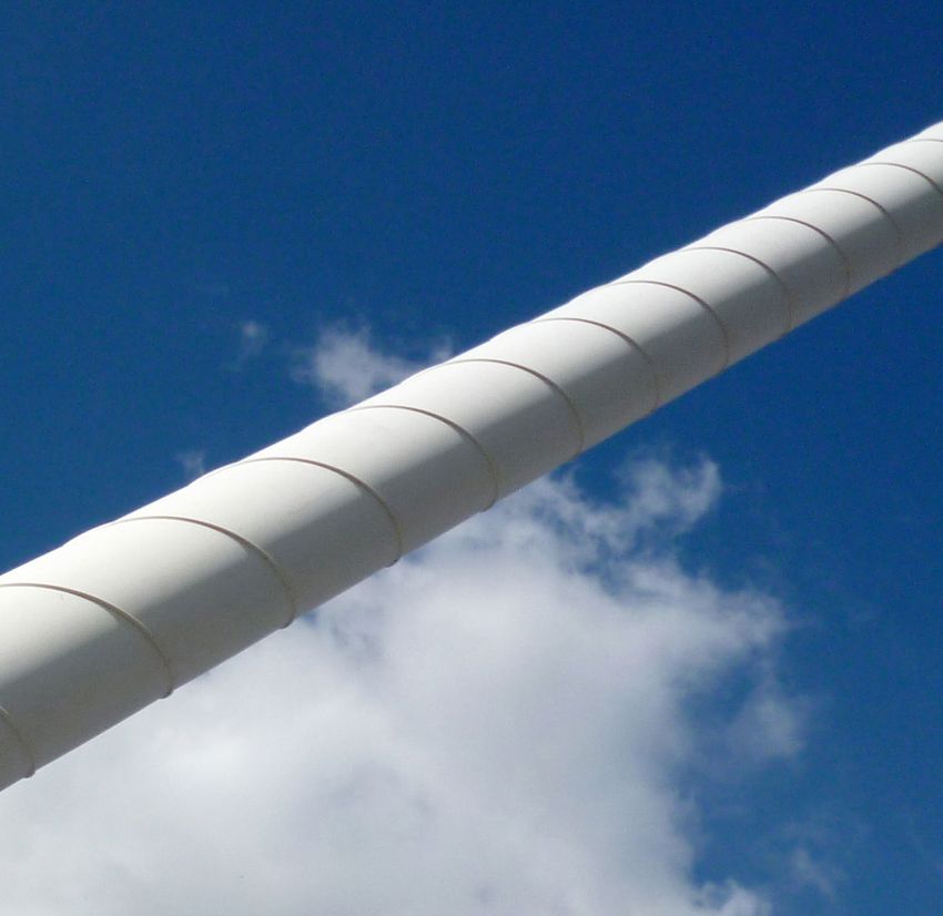
Outer Stay Pipe
Standard Pipe
■■ HDPE pipes serve as protection
against environmental influences
and are typically used as outer
covers of DYWIDAG Stay Cables.
Main characteristics:
■■ Wind load reduction at the cable
■■ Outer helix with demonstrated
efficiency against rain-wind induced
cable vibrations
■■ Co-extruded or fully colored pipes
■■ Wide range of colors Standard Duct
■■ The excellent UV-resistance has been
proven in accelerated aging tests
■■ Steel or stainless steel pipes are
available on special request
Slim Duct
■■ For long span bridges, lateral wind
loading at the cables needs to be
taken into account for pylon design.
To reduce the wind load, DSI offers
slim sheathing with reduced pipe
diameters. Slim Duct
HDPE Sheathing with Helix
Stainless Steel Duct
25Cable Damping
Slender supporting structures and Depending on the respective cable By experience, DSI recommends to
long cable lengths make stay cables parameters, each cable is more or less increase a cable’s inherent damping by
susceptible to vibrations. Big vibration prone to vibration. Longer cables are using additional damping devices for
amplitudes may result in damages to the more likely to vibrate than short ones. cable lengths above 80m.
cable due to bending and fatigue loads. Nevertheless, cables with lengths above
This decreases a cable’s d urability and 200m have been installed without Cables start vibrating when they are
may even endanger structural safety. additional dampers without any vibration excited. Please find following some
problems. On the other hand, even very excitation causes and methods for
short cables sometimes need dampers. mitigating their effects.
26Cable Damping
Excitation Causes
Buffeting Wake Galloping Parametric Excitation
■■ Wind causes drag, lift and moment ■■ Wake Galloping occurs at cables that ■■ Parametric excitation is caused if the
forces on cables that result in are closely spaced in wind direction. excitation acts on other parts of the
cable vibrations. Depending on Vortexes behind one cable excite the structure (such as the pylon), and if
the boundary conditions, inherent cable that is next to it and lead to this vibration is transferred into the
damping of a stay cable without vibrations. cables.
additional damping might not be high ■■ DSI not only supplies the appropriate
enough to decrease these vibrations Iced Galloping damping devices but also supports
to an acceptable amplitude. bridge designers and owners in
■■ Ice that sticks to a round cable can choosing a damping concept that is
Vortex-Shedding alter its cross section in such a way customized to their specific project
that galloping occurs above a critical needs.
■■ Uniform wind flow causes turbulent wind speed.
vortices to detach, alternating from a Outer Helical Fillet
cable’s top and bottom side, so that Rain-Wind induced Vibrations
vibrations are caused. The amplitudes ■■ To mitigate rain-wind induced
are usually small compared to the ■■ During specific combinations of rain vibrations, a double helical fillet is
cable diameter. However, resonance intensity, wind speed, wind direction applied on the surface of outer stay
of the vortex shedding frequency and and cable inclination, water rivulets pipes
cable eigenfrequencies can result in arrange at the cable’s top and bottom
■■ Different diameters have been tested
larger amplitudes. surface. Due to wind, they move
in climatic wind tunnel tests
a few degrees around the cable
Galloping circumference and induce vibrations ■■ Demonstrated drag coefficient of
into the cable. This happens at CD = 0.6 for large cable diameters
■■ Galloping affects rectangular shapes relatively low wind speeds.
or round shapes with asymmetry.
If the wind speed is above a critical
value, vortexes detach from the edges
and create similar effects as vortex
shedding. However, contrary to vortex
shedding, galloping results in high
amplitude vibrations.
Drag Coefficient for Stay Pipe
0.8
Drag coefficient CD
0.7
0.6
0.5
0.5 1.0 1.5 2.0 2.5 3.0 3.5 4.0 4.5 5.0 5.3
Reynolds number Rc x105
α = 0° α = 180°
27Cable Damping
Damper Design
■■ Sufficient damping prevents cables Correlation of
from vibrating. DSI recommends Achievable Damping Coefficient, Damping Ratio and Scruton Number
damping values of at least 3–4%
logarithmic decrement δ to be 1.25 16.5
reached for the first two to three
vibration modes depending on each
cable’s boundary conditions and on 1.00 13.2
project specific requirements. These
Damping Ratio ζ [%]
Scruton Number Sc
damping values can usually not be
achieved by inherent cable damping 0.75 9.9
so that additional damping is required.
■■ External viscous dampers provide very
effective supplementary damping. 0.50 6.6
■■ Special software developed for DSI
0.25 3.3
External Viscous Damper
0 0
■■ Efficient dampers can be computed 0 400 800 1,200 1,600 2,000
for each cable taking into account c [kN* s/m]
several vibration modes Mode 1 Mode 2 Mode 3 Mode 4 Mode 5
■■ In plane, the damper is sufficient to
also suppress out of plane vibrations
■■ Slender and aesthetic design;
available in several colors
Vandalism Protection Pipe
Compaction Clamp
External Viscous Damper
28Cable Damping
Vandalism Protection Pipe
Exit Pipe
Compaction Clamp
Internal Viscous Damper
Flange Connection with
high-strength Bolts
Internal Viscous Damper
In addition to external viscous dampers, DSI also offers internal viscous dampers
Vandalism
that are attached to the exit pipe. Protection Pipe
■■ Damping forces are transmitted from ■■ Since DSI housed dampers do not
the damper through its steel housing require a connection point on deck,
and exit pipe into the recess pipe, they can be used at virtually any cable
from where they are transferred into position
the superstructure ■■ Increased durability is a benefit of
■■ Housed dampers are advantageous housed dampers: they are not affected
due to their avoiding additional by weathering
support structures for connection to ■■ A stiff flanged connection is required
the bridge deck
Exit Pipe
Internal Rubber Damper
Compaction Clamp
Especially used for short and medium
cable lengths Flange Connection with Internal
high-strength Bolts high efficiency Rubber Damper
■■ Internal rubber dampers are placed
inside the exit pipe parallel to the
cable axis
■■ Their elastomeric high efficiency
material dissipates vibration energy
while deforming when subject to shear
stress
29Full Size Testing
DYWIDAG Stay Cables have been Standard Fatigue and Tensile Testing
successfully tested in numerous static
and fatigue tests in compliance with fib, ■■ Applying 2 million load cycles DYWIDAG Stay Cable testing has
SETRA and PTI recommendations. Tests ■■ Stress range of 200N/mm² also been successfully conducted in
have been conducted in collaboration additional full size tests with increased
■■ Upper load level of 45% GUTS
with renowned Universities such as requirements in terms of upper load and
CTL, TU Munich, TU Vienna, MPA ■■ Inclined anchorages of 10mrad additional angular deviation of the cable
Braunschweig or DTU Copenhagen. system.
SETRA
Fatigue and Tensile Testing with higher load level and additional Transverse Deflection
■■ Application of 2 million load cycles
■■ Stress range of 100N/mm²
■■ Upper load level of 60% GUTS
■■ Anchorages inclined by 10mrad
■■ Deviation of ± 25mrad in transversal
direction
30Fire Protection
Fatigue and Tensile Testing with additional Transverse Deflection (Setra)
■■ Applying 2 million load cycles
■■ Stress range of 200N/mm²,
■■ Upper load level of 45% GUTS
■■ Transverse deflection resulting in
cyclic angular deviation from
0 to 10mrad
Increased Load Cycle Testing – 10 Million Cycles
■■ Application of 10 million load cycles
■■ Stress range of 200N/mm²
■■ Upper load level of 45% GUTS
■■ Anchorages inclined by 10mrad
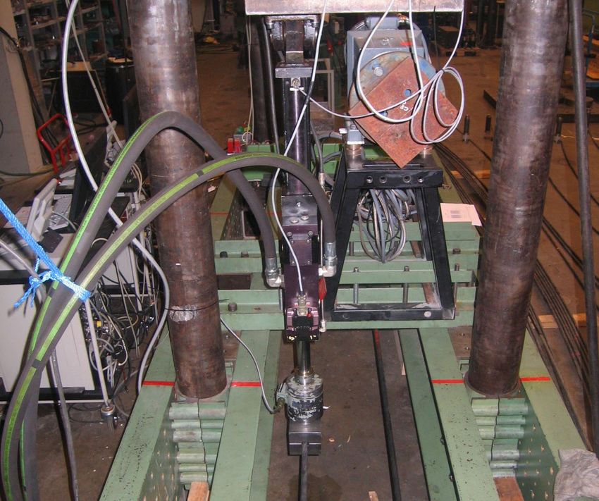
31Full Size Testing Monostrand Fatigue Testing under Reversed Cyclic Flexural Loading A series of bending fatigue tests on ■■ galvanized, waxed and PE-coated 7 wire strands 0.62" with an ultimate tensile strength of 1,860N/mm² were successfully performed. They proved that the standard protective measures of the sealing unit within the DYNA Grip® Anchorage are effective for fatigue bending without the additional use of a guide deviator. ■■ Application of 2 million load cycles ■■ Different upper load levels varying from 45% to 60% GUTS ■■ Static inclination at the anchorage between 0.6° and 3.0° ■■ Additional angular deviation at the center of the strand between ± 10mrad and ± 35mrad 32
Full Size Testing

Leak Tightness Test
DSI anchorages are fully resistant to any
infiltration of water. Tested according to
PTI requirements:
■■ Subsequent to fatigue testing
■■ For 96 hours
■■ With a 3m water head

And tested according to fib and Setra
requirements with:
■■ Up to 3m water head
■■ Several longitudinal and transverse
   load cycles
■■ Temperature cycle 20°C – 70°C

                                             33
Cable Installation DSI has developed various methods to optimize and simplify cable installation procedures depending on site specific space and time constraints. ■■ The outer sheathing is welded to its required length directly on site using heated tool welding and is then lifted into an inclined position ■■ Strands are uncoiled either from wooden reels or are provided reel-less. They are installed and stressed one by one using lightweight equipment ■■ Strand installation is performed using small winches or pushing devices ■■ Hardware configuration can be adjusted to site conditions to ensure a fast, customized solution that minimizes costs and cycle times ■■ Afterwards, strands are installed into the sheathing, and the complete cable is lifted into its final position ■■ Subsequently, all strands are stressed If required, the complete cable can also be preassembled on the ground first. 34
35
Stressing
DYWIDAG stressing equipment is designed to ensure an economic and convenient installation process.
ConTen Stressing
The patented (EP2307637 B1; Change of Strand Force depending on t he Number of Stressed Strands
US8702066 B2) ConTen System uses a
monojack that is hydraulically coupled 100,0
Force in each Individual Stressed Strand of
one Sequence after Stressing Strand i [kN]
with a control unit. The system is
applicable both for DYNA Grip® and 90,0
DYNA Bond® Stay Cable Systems.
80,0
■■ Every single strand is stressed
individually 70,0
■■ A special calculation method –
60,0
developed by DSI – determines the
force for the first strand and the
50,0
corresponding forces for all sub
sequent strands 40,0
■■ This allows monitoring the stressing
operation up to the required final cable 30,0
force 0 10 20 30 40 50 60
■■ Equal forces are achieved in all Number of Installed and Stressed Strands
strands within one cable at the end of First Stressing Sequence Second Stressing Sequence
the stressing operation
■■ Influences of temperature and
load changes during stressing are
automatically eliminated
In case of very short strand elongation
values or if the cable force needs to be
adjusted, retensioning or releasing of the
complete cable is possible by turning
the ring nut. Special compact gradient
jacks are available for this purpose
■■ Gradient jacks may be moved fully
assembled or disassembled into their
main components so that they fit even
through small openings
■■ The same economic type of hydraulic
pump can be used for both stressing
systems. The pump is light, robust and
has proven its reliability in many stay
cable projects
Standard Hydraulic Pump Gradient Jack
36You can also read