Electric Machines and Drives for X-by-Wire Systems in Ground Vehicles
←
→
Page content transcription
If your browser does not render page correctly, please read the page content below
Electrical Drives for Drive-by-Wire Systems in Surface Vehicles                                      BOLOGNESI Paolo

                                                  Electric Machines and Drives
                                                     for X-by-Wire Systems
                                                       in Ground Vehicles

                                      P. Bolognesi, O. Bruno, A. Landi, L. Sani, L. Taponecco
               Department of Electric Systems & Automation - University of Pisa
 Via Diotisalvi 2 - 56126 Pisa - Italy - fax: +39-050-565333 - e-mail: p.bolognesi@ieee.org

Keywords Automotive applications, automotive components, emerging technologies

Abstract
The transition from conventional mechanical-hydraulic actuation systems to innovative "x-by-wire"
solutions in the treatment and transmission of pilot's commands represents a new leading edge for the
automotive industry. Relevant improvements are indeed expected from the introduction of electrical
drives suitably controlled by hierarchical computer-based management systems interconnected through a
field bus: better performances, greater overall safety and reliability, higher efficiency, lower emissions,
reduced maintenance etc. Starting from the servo-systems presently adopted, this paper aims to presents
an overview of the main issues and of the most interesting solutions proposed in the technical literature,
particularly referring to the aspects regarding electric machines and drives. The potential benefits with
respect to conventional systems are highlighted, and some orienting considerations are formulated
referring both to conventional powertrain structures and to hybrid and electric vehicles.

1.- Fly-by-wire: the predecessor
Since the end of the second world war, as the diffusion of air transportation led to the development of
larger and heavier airplanes facing more and more stringent safety regulations, an increasing research
effort was devoted from the avionic industry to the development of "fly-by-wire" solutions employing
electro-hydraulic or purely electric systems as a replacement for the conventional mechanical and/or
hydraulic structures previously used for the transmission of the pilot's commands to the actuated devices
(flaps, injectors etc.). In fact, as a general rule the benefits correlated to the transition from mechanical to
electric systems become more and more evident as the size of the system augments, in terms of both
simplicity, flexibility, efficiency, performances and weight. Moreover, the adoption of active command
leverages, equipped with suitably controlled actuators, permits to provide the pilot with a useful wrench
feedback, allowing him to virtually sense the intensity of the effort required to execute his commands
just as if a mechanical connection still exists. Finally, nowadays fly-by-wire systems have evolved from
their original pure servo-system role, aimed to simply "amplify" the physical effort of the human pilot to
allow him driving large airplanes, to a more critical role thanks to the introduction of computer-based
supervision and management systems charged to reliably perform sophisticated functions such as stability
control, route-tracking and so on. Under this point of view, the higher precision and better repeatability
and dynamic performances of electric drives represent then the natural choice in the selection of servo-
systems. Consequently, nowadays only small tourism airplanes are still equipped with conventional
systems, while modern large airplanes extensively employ fly-by-wire systems, although in many cases
indirect hybrid electro-hydraulic configurations are still employed using electromagnetic servo-valves to
regulate the operation of hydraulic actuators. Nevertheless, the direct employ of electric drives is steadily
growing and all the main typologies are under careful evaluation (e.g. [1]), since they already proved to
be able to provide reliability and robustness levels even higher than conventional solutions when suitable
design criteria are adopted.

EPE 2003 - Toulouse                                               ISBN : 90-75815-07-7                          P.1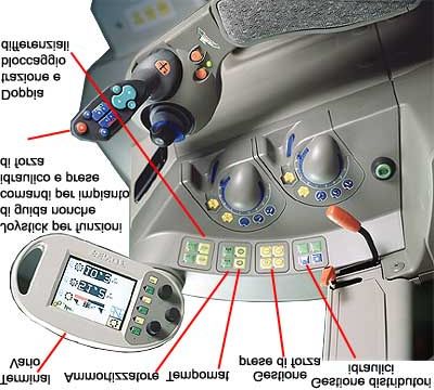
Electrical Drives for Drive-by-Wire Systems in Surface Vehicles                                  BOLOGNESI Paolo

2.- By-Wire systems in ground vehicles
2.1- General considerations
Basing also on the positive experience in avionic applications, the employ of electrical drives is
continuously growing even in the automotive ambit, although till now it has been mainly limited to non-
safety-critical tasks such as windows lift, electric doors lock, fans, wipers etc. Nevertheless, the first
actual by-wire solutions were developed about 2 decades ago (e.g. [55]) referring to throttle control,
while in the last decade further applications appeared in mass-production vehicles, including fuel
injection, electric-assisted steering and safety-assistance systems such as ABS (e.g. [2,3,4]).
Anyway, the steep trend in the total rated power of the electric devices present on-board of ground
vehicles, especially of high-end class, made already evident, several years ago (e.g. [5]), the necessity to
consider a strong improvement of the power system involving a suitable raising of the battery voltage and
a massive employ of static converters and switches. In fact, such remedies may permit to avoid
prohibitively high currents otherwise associated with the low voltage levels conventionally adopted (typ.
14 V), and to achieve a better efficiency and operation flexibility in supplying the loads, besides gaining
the possibility to separate the power and signal paths. For example, significant fuel savings may be
expected from the employ of electrically operated pumps and compressors, e.g. in air conditioning
systems, since the rotation speed may be finely regulated to comply the actual requirements
independently on the engine operation. Presently, as a result of industrial workgroups operating since
1995, a standardization hypothesis has been widely agreed towards a x3 increasing of the present voltage
levels in conventional and minimal-hybrid vehicles, leading so to a rated voltage of 42 V in the on-board
power net (e.g. [6]). During a first transition phase, a suitable dc/dc converter will be probably used to
also supply a secondary bus keeping the old 14 V voltage level, in order to permit a smoother transition
towards the new standard for low-cost mass-production devices, such as lamps. On the opposite, despite
the perplexities correlated to electric shock safety issues, under the technical point of view significantly
higher voltage levels, in the order of several hundreds V, should be employed for the main power bus of
series hybrid or purely electric vehicles, especially of large size: in fact, in this case unwisely large
currents should otherwise be faced, since the whole propulsion power is provided in electric form.
Consequently, the importance of electromagnetic and electronic devices inside ground vehicles is
forecasted to continuously grow and to represent a very interesting business opportunity (e.g. [7,8]),
since the incidence on the vehicles' cost should raise up to 25% of the overall value, with a gross 50%-
20% share of the complete drive-actuator price between electronic part and electric machines, despite the
natural decreasing trend in the specific cost of the devices thanks to large scale production. Recently, the
actual introduction of mass-production car models using brake and steer by-wire systems was forecasted
to take place within few years (e.g. [9]), while several examples have already gained the market for
special purpose vehicles, both in military and industrial ambits.

2.2- System architecture
In its widest interpretation, often named "x-by-wire", a by-wire solution should involve the full
replacement of conventional mechanical and hydraulic transmission and actuation systems with electric
power cables supplying electromagnetic devices through static converters driven by local electronic
controllers. Such local controllers should be connected through a digital communication network - field
bus - to a central computer-based supervision/management unit, constituting then a hierarchical control
structure (e.g. fig.1). The central unit coordinates the peripheral control units implementing suitable
operation strategies basing on the pilot's commands, received through a suitable human interface, besides
on the vehicle's current state and on the environmental conditions, reliably sensed through suitable sets
of sensors. Referring to a conventional ground vehicle's structure, the functions usually included in the
more restrictive "drive-by-wire" definition are constituted by engine regulation, steering and braking; in
more general terms, x-by-wire systems may also include the operation of starter/generator, transmission
and active suspensions, besides other auxiliaries such as air conditioner, electric windows and doors,
fans, wipers etc. (e.g. fig.2). The by-wire system would play an even more important role in case of
hybrid or purely electric vehicles, since all the electric drives used for both main generation and
propulsion should be also properly managed in coordinated way to actually achieve the potentially
notable benefits deriving from the adoption of such configurations, i.e. low fuel consumption and low
emissions, improved drivability etc.

EPE 2003 - Toulouse                                               ISBN : 90-75815-07-7                      P.2
Electrical Drives for Drive-by-Wire Systems in Surface Vehicles                                                          BOLOGNESI Paolo

          Fig.1 - Typical structure of drive -by-wire system [11]                        Fig.2 - Functions of x-by-wire system [9]

2.3- Potential benefits
In general terms, for any ground vehicle the employ of electric drives in spite of the mechanical systems
presently adopted for the transmission and actuation of the pilot's commands might permit to achieve
significant improvements under several points of view. In fact, by-wire systems permit to easily adopt
different optimized paths for the signal and for the power cables, which turns into an overall lower gross
volume than required by conventional mechanical or hydraulic connections. A far more flexible design of
the vehicle results then possible, allowing to optimize the powertrain's layout basing on structural
considerations, to increase and make more comfortable the payload space, and to shape as desired the
pilot command interface. This fact may turn into a higher passive safety of the vehicle, since parts that
become notoriously dangerous in case of accident, such as the steering column, the brake pedal and
possibly also the steering wheel, may be completely eliminated. The user interface may become also
more user-friendly, for example requiring only hand commands through a cloche-like device that may
completely replace the present pedals, levers and the steering wheel. The overall performances of the
vehicle may be also improved when the supervision system is enabled to apply suitable strategies even
during normal operation, to optimize the vehicle's response basing on its current status, on the pilot
directives and on other significant variables, such as road slope, pavement conditions etc. When fully
exploited, this possibility should permit to further increase the active safety of the vehicle with respect to
the presently existing partial systems, such as ABS. Moreover, an accurate management of the engine
and power transmission behavior, eventually joined with the adoption of an integrated starter-alternator
system, may permit to achieve significant fuel savings and pollution reductions by optimizing the
combustion process and selecting the best engine speed and gear ratio per each operating condition.
Further fuel savings should also derive from and overall higher efficiency of several auxiliary systems,
such as pumps and compressors, which are presently operated at randomly variable speed directly from
the engine, and are often regulated in dissipative way acting on controllable output valves. Finally, in a
mid-long term perspective even a cost reduction seems possible with respect to conventional systems: in
fact, by-wire solutions should permit wider synergic savings by leveraging on the possible modularity of
the subsystems, especially for what concerns control and data transmission apparatuses, although also
the power devices may be used to equip different vehicles featuring similar sizes.

2.4- Main present issues
The major issues that are still presently slowing the diffusion of drive-by-wire systems are correlated
with 2 aspects: on one hand, existing regulations and customers' expectations dictate safety, reliability
and robustness specifications which are not much lower than for airplanes (e.g. [10]); on the other hand,
a wide diffusion in the automotive mass market will become possible only when manufacturing and
maintenance costs will result much lower than in avionic applications. Consequently, a strong engineering
effort is required to design solutions targeted to the automotive market, providing suitably reliable fail-
safe capabilities achieved through redundancy and design optimization (e.g. [11,12]) while still featuring
acceptable costs obtained by leveraging on mass production and on the exploitation of all possible
synergies. In this ambit, presently a greater attention is devoted to the development of fault-tolerant
digital communication systems featuring an adequate real-time capability, particularly basing on the

EPE 2003 - Toulouse                                               ISBN : 90-75815-07-7                                               P.3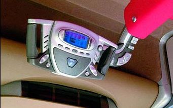
Electrical Drives for Drive-by-Wire Systems in Surface Vehicles                                                                 BOLOGNESI Paolo

deterministic approach implemented in the time-triggered-protocol (e.g. [13]). Nevertheless, wide
possibilities of optimization also exist for the power and sensor components: in fact, till now in most
cases a simple duplication of conventional devices has been considered to achieve the required
redundancy, while only a few examples of integrated fails-safe designs have been proposed.

3.- Engine regulation
3.1- Fuel injection & sparking
Nowadays, most of newly produced engines for ground vehicles, especially of Diesel type, feature a
"direct fuel injection" system, probably representing the first example of by-wire subsystem that
massively entered the automotive market. The system consists of suitable electromagnetic actuators able
to precisely modulate the quantity of fuel to be introduced in each cylinder in sprayed form, and/or the
precise instant of the injection within each cycle (e.g. [14], fig.3). Presently, such devices are driven,
through static switches, from a more or less sophisticated digital management unit that operates sensing
the throttle pedal position, the engine status and the "lambda probe" output when a catalytic retrofit is
present, as usual. The fuel injection regulation might be also coupled to the control of the precise instant
of sparking in gasoline engines, although within a limited range. In any case, the control unit, besides
managing particular situations such as start-up, is charged to apply suitable strategies aimed to optimize
the overall performances under different points of view, such as performances, fuel consumption and
polluting emissions. By modifying the control strategy it results then often possible to appreciably affect
the apparent character of the engine as felt from the pilot, ranging from "sporty" to "mixed use" to "fuel
save". This technology seems to have now gained some degree of maturity, although research efforts are
still devoted to further improve the electromechanical actuators employed (e.g. [15]).

3.2- Cylinder valves
Presently, the standard solution to manage the correct time sequence of air or air-fuel mixture inlet and
exhausts outlet for each cylinder of internal combustion engines consists in using mechanical valves
directly acted from a camshaft that is rigidly coupled to the main engine shaft through either gears or
toothed pulleys-belt. Although fairly simple, reliable and inexpensive, such solution forces to use a unique
and pre-defined cinematic profile linking the valves' positions to the piston position: such profile must be
then selected at design stage as a suitable compromise over the whole operation range of the engine.
Nevertheless, interesting improvements, under both the performance, fuel consumption and emissions
points of view, may be achieved by coupling the fuel injection technique above recalled to a suitable real
time adjustment of the valves cinematic profile basing on the actual operating conditions. To exploit such
possibility, the employ of linear electromechanical devices has been recently proposed referring either to
a direct operation of each singe valve, suitable for gasoline engines, and to an indirect operation of
multiple valves by means of an intermediate hydraulic circuit regulated by electric operated valves, more
suitable for Diesel engines due to the higher pressures calling for higher operation forces. In both cases,
the capability to develop bi-directional forces is required along a limited stroke length, leading to consider
either permanent magnets mono-phase machines or reluctance machines featuring permanent magnets or
twin windings (e.g. [16], fig.4). In particular, the employ of voice-coil actuators, thanks to their simplicity
and simple drivability, may then result of interest for the indirect electro-hydraulic configuration, where a
good dynamic capability is expected but the required forces are less relevant (e.g. [17]).

  Fig.3 - Fuel injection system [15]                              Fig.4 - Reluctance linear actuator   Fig.5 - Reluctance rotary actuator
                                                                       for cylinder valves [16]               for throttle valve [19]

EPE 2003 - Toulouse                                                         ISBN : 90-75815-07-7                                            P.4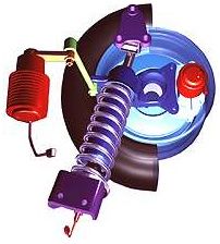
Electrical Drives for Drive-by-Wire Systems in Surface Vehicles                                    BOLOGNESI Paolo

3.3- Throttle valve
The quantitative regulation of the air or air/fuel mix inlet of engines is usually performed by means of a
rotating throttle valve, whose angular position is directly determined, in the classical configuration, by the
position of the throttle pedal. The possibility to eliminate the direct mechanical connection and to drive
this valve by means of an electromechanical actuator, investigated more than 2 decades ago [55], has
gained a fair diffusion in recent years to permit an optimized by-wire control of the engine behavior
especially when coupled to fuel injection or valves control. Although relatively conventional solutions
employing classical d.c. drives have been considered (e.g. [18]), the fact that the required rotation span is
typically within the range 0-90º permits to effectively employ limited stroke actuators, which may offer a
less expensive alternative. In particular, the employ of monophase reluctance actuators results potentially
very interesting thanks to their structural simplicity, robustness and low manufacturing cost, deriving
from the possibility to adopt a single toroidal coil and to employ inexpensive soft-magnetic materials
including bulk iron (e.g. [19], fig.5). Nevertheless, more sophisticated designs, including permanent
magnets, may permit to achieve a cogging force determining a well-defined null-current stable position,
which may be associated to the idle condition of the engine. Although resulting in a more expensive
actuator, such solution may permit to eliminate the springs-pinlock system otherwise used to determine,
for safety reasons, a self-idle behavior of the throttle valve in case of fault of the by-wire system.

4.- Integrated starter/generator drive
Presently, in most of conventional ground vehicles a d.c. machine is used as starter to accelerate the
engine up to self-sustain speed during start-up, while an alternator coupled to a rectifier - voltage
regulator converter is used as on-board generator to supply the electrical loads and to charge the battery.
Such solution, derived from the pre- power electronics era when a second separately-excited d.c.
machine was used as generator, results relatively simple and not very expensive, although in conceptual
terms the employ of a unique electric machine able to perform both tasks should clearly represent an
improvement. Moreover, the presently low cost of such solution is often achieved at the expense of
technical quality and fuel consumption: in fact, the alternator is usually a simple price-optimized Lundell
type, designed almost neglecting efficiency (e.g. [20]). When considering the increasing environmental
concerns in the perspective of the constant raising of the total electric power required on-board of
vehicles, such conventional design criteria appear nowadays less and less acceptable. Moreover, the
concept of achieving fast (i.e.
Electrical Drives for Drive-by-Wire Systems in Surface Vehicles                                                           BOLOGNESI Paolo

a supercapacitors bank (e.g. fig.6). In such configuration, the management unit could employ the fast
dynamic response of the generation drive to provide a variable torque that compensates, as far as
possible, the variable torque ripple eventually required by the vehicle operation condition and by the
pilot's commands, in such a way that the engine may provide only a slowly variable power profile
tracking the "mean" power required for motion and for keeping the charge level of the storage system
within acceptable limits. Naturally, thanks to the bidirectional drive behavior such system may permit to
recover part of the braking energy, when its operation is suitably coordinated with the mechanical
brakes. Moreover, when a clutch is inserted between the engine and electric machine, the system might
even permit to operate the vehicle in purely electric mode, although for short travels at mid-low speed.
Nevertheless, even such a limited capability might significantly reduce the pollution problems due to slow
stop-and-go circulation and parking in urban areas. Recently, a few variants of popular cars
implementing this concept have begun to be proposed on the market (e.g. Honda Insight®, [53]).
For what concerns the machine type to be used, the possible employ of both permanent magnets
synchronous, induction and switched reluctance machines has been proposed, mainly assuming a 3-
phase structures and considering both disc-shaped axial-field typologies and short-cylinder-shaped radial-
field structures featuring a large number of poles to better exploit the wide external diameter. Induction
and reluctance machines would be intrinsically more suitable for operation at constant power over a wide
speed range (e.g. [21]), but the former presents intrinsically worse efficiency levels that let it appear not
wise for high efficiency vehicles. On the other hand, switched reluctance machines still suffer of the
torque ripple and acoustic noise problems recalled in paragraph 6. Alternatively, suitably designed
permanent magnets synchronous machines should be seriously considered: in fact, when suitably
designed they may provide very interesting specific performances while tolerating a reasonably wide
field-weakening operation range. In fact, it must be kept in mind that achieving good performances from
the engine implies to let it operate within a not very wide speed range. Finally, as alternative to a pure
flywheel-like behavior, the presence of a fast dynamics generation drive may be also exploited to actively
compensate the torque ripple due to the engine, in such a way to achieve a good speed stabilization even
in case of low inertia rotor (e.g. [22]).

5.- Transmission regulation
5.1- Clutch
Friction clutches are widely employed in the automotive ambit to either disconnect the moved shaft from
the main shaft, e.g. for gear ratio change, or to gradually engage them, e.g. during startup. In fact, the
only conventional alternative is represented by hydraulic joints employing pump-turbine pairs:
nevertheless, they result more complex and expensive while providing a lower efficiency during steady
state operation. Since several years, by-wire controlled electromagnetic clutches have been introduced in
competition cars to reduce the pilot's physical effort and to optimize the shift process, as described in
next paragraph. In its simplest configuration, a by-wire friction clutch includes then a linear
electromechanical actuator able to provide appreciable forces with a limited useful stroke, to contrast the
action of the springs usually employed to keep pressed the friction disks, thus engaging the 2 shafts. For
such task, a monophase reluctance machine may probably constitute the best compromise between cost
and performances; nevertheless, when a suitably designed permanent magnets machine was adopted, the
springs may be even eliminated by exploiting the cogging force. A different possibility consists in using an
electromagnetic particle clutch, grossly consisting of a suitable housing hosting a coil linked with a

  Fig.6 - Dual-voltage structure with ISG                         Fig.7 - Electromagnetic clucth [23]   Fig.8 - In-wheel motor [26]

EPE 2003 - Toulouse                                                    ISBN : 90-75815-07-7                                           P.6
Electrical Drives for Drive-by-Wire Systems in Surface Vehicles                                    BOLOGNESI Paolo

magnetic circuit including 2 surfaces, connected with the input and output shafts, which are separated by
a small gap partly filled with ferromagnetic powder featuring a suitable grain and low residual induction
(e.g. [23], fig. 7). When the coil is excited, a magnetic field is created in the gap region, whose intensity
depends on the supplied current: such field induces in turn a partial magnetic polarization of the iron
powder, which varies its macroscopic apparent mechanical strength and its adhesion force towards the 2
facing surfaces, determining so an equivalent friction effect. Such type of clutch is already employed,
under control of the relative management unit, in several automatic continuously-variable-transmission
systems presently equipping some popular small cars (e.g. Nissan Micra®, Fiat Punto®).

5.2- Gearbox
When a variable ratio gearbox is used in the transmission chain, presently in most cases it is operated in
direct manual way from the pilot by means of suitable levers. Since several years, in competition cars the
employ of so called "robotized gearboxes" has been introduced, usually in association with
electromagnetic clutches as above recalled. In such systems, the pilot acts onto 2 buttons, usually located
in the steering wheel, to send the shift-up or -down commands to the management. In case the
commands are applicable, the management unit instructs suitable actuator drives to perform the required
operations in the correct sequence, i.e. clutch disengagement, gear shift and clutch reengagement,
minimizing so the shift time and significantly reducing the physical effort of the pilot. Since a few years,
some car manufacturers begun to propose similar solutions also for mass-production vehicles, usually
referring either to high-end models (e.g. BMW S3®, [44]) or to city-cars (e.g. Renault Twingo ®) as
alternative with respect to a fully automatic transmission. In a true x-by-wire vehicle, the clutch-gearbox
group might be even controlled by the central management unit in fully transparent way from the pilot's
point of view, automatically selecting in real time the most suitable gear ratio depending on the pilot's
commands, on the vehicle status and on the environmental conditions.

6.- Propulsion drives
Although not necessarily constituting a part of x-by-wire structures, since they are absent in conventional
powertrain configurations, in case of series-hybrid or purely electric vehicles a very significant part of the
on-board electric system is constituted by propulsion drives. Till about 3 decades ago, the only typology
of electric machines used for such purpose was constituted by d.c. machines, in most cases equipped
with series excitation winding. In fact, under constant supply voltage their mechanical curve presents a
descending trend recalling the constant-power relationship singled out by time as the most suited for
propulsion purposes. The regulation was indeed limited to rheostatic startup and eventually to tap-
variations of active turns in the excitation winding, applying the same methods used for electric railway
systems. Nowadays, thanks to the wide availability of a.c. drives, d.c. motors are less and less employed
due to their worse features in terms of cost, maintenance requirements and robustness.
A relevant research activity has been developed to compare the different typologies of a.c. motors and
converters for ground vehicles' propulsion applications (e.g. [24]). In particular, permanent magnets
synchronous machines, possibly of anisotropic type, have been shown to be able to provide very high
specific power and torque levels, although specific design criteria must be adopted to achieve a
sufficiently wide constant-power operation range since such machines would be intrinsically less suited
for field-weakening operation (e.g. [25]). Anyway, disc versions of PM brushless machines were also
developed to be directly incorporated in the wheel structure, successfully proving the possibility to
achieve a remarkable integration level (e.g. [26], fig. 8). A potentially very interesting alternative is
represented by reluctance machines, in both the synchronous and switched versions, although they are
not yet widely available as industrialized products. In fact, they may exhibit a very wide operation range
intrinsically allowing field-weakening, while their simple structure, not requiring expensive magnetic
materials, should permit to lower manufacturing costs; their intrinsic robustness should also minimize the
maintenance requirements. Nevertheless, several problems still limit the diffusion of switched reluctance
machines: in fact, especially when high performance design criteria are adopted, a correct shaping of
current waveforms becomes critical for achieving both a suitably small torque ripple and an acceptably
low acoustic noise, although these 2 targets might also conflict. Conventional induction machines
represent instead the most easily available and presently less expensive solution, although potentially also
the less efficient thus resulting less suited especially for battery-operated vehicles.
Under this point of view, an important aspect that may significantly affect any drive system is the supply

EPE 2003 - Toulouse                                               ISBN : 90-75815-07-7                        P.7
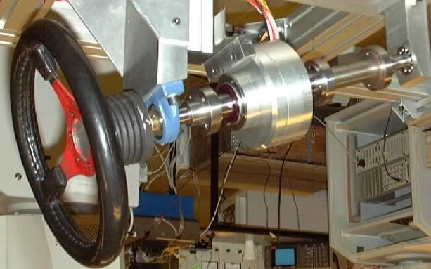
Electrical Drives for Drive-by-Wire Systems in Surface Vehicles                                  BOLOGNESI Paolo

voltage level. In fact, when for safety reasons the maximum on-board voltage results relatively low with
respect to technically suited values, leading so to unwisely relevant currents, worse results may be
expected both in terms of efficiency and specific performances. In such case, the employ of resonant or
semi-resonant converters might constitute a partial remedy to limit switching losses, although usually
involving higher costs and more complex control systems (e.g. [27]).

7.- Steering-by-wire
7.1- Actuation
In the traditional ground vehicles' structure, the steering function is accomplished by rotating the wheels
belonging to the foremost axle around a grossly vertical axis with equal steering angles, since they are
usually linked by means of a transversal bar. In some cases, especially for heavy trucks or industrial
vehicles, the same function is implemented also on a second axle, again by means of fixed mechanical
links. The steering angle is then directly determined from the pilot by turning the steering wheel, which
drives the transversal bar through the steering column and a gearbox with pinion coupling. To alleviate
the correlated physical effort required to the pilot, since many years steering-assistance systems were
introduced, gradually gaining a wide diffusion up to small cars. These systems, having a purely hydraulic
or pneumatic structure directly powered from the engine through pumps, usually operate directly on
steering column as simple torque amplifiers. Nevertheless, such systems exhibit a poor adjustability and a
low efficiency, determining an appreciable increasing of fuel consumption: in fact, the pump is operated
continuously and is designed for the minimum engine speed, providing so the maximum potential effect
during high speed cruising, i.e. just when the servo function is less required and even potentially
dangerous. To overcome such drawbacks and to also save on weight and volume, since a few years
electric steering-assistance systems have been introduced also in the automotive market (e.g. [28], fig.9).
Presently, such systems usually include a permanent-magnets d.c. motor gear-coupled to the lower part
of the steering column below a calibrated portion, whose torsional deformation is sensed to determine the
torque applied by the pilot to the steering wheel (e.g. [29]). The motor is driven by a chopper, directly
supplied from the battery, under the control of a local management unit, which basically makes it operate
as a torque amplifier leveraging on the intrinsic stability of this operation mode when the pilot is assumed
to turn the wheel with a position-control-like approach. In this case, the intensity of the servo effect may
be easily adapted to the actual necessities either in automatic way, diminishing it as the speed raises, or
directly by the user through a manual selection; in both cases, appreciable fuel savings are achieved.
Different types of rotary electromagnetic actuators, including collector-less induction, reluctance and a.c.
permanent magnets one, have been considered also for this task (e.g. [30]), to eliminate the brush-related
maintenance and potentially involving lower manufacturing costs. Recently, the employ of by-wire drive
systems to provide an automatic steering capability for the rear axle has been also introduced in the
automotive market, especially referring to sport-utility vehicles (e.g. [48], fig.10). Such systems, derived
from servo-steering systems (e.g. fig.11), may implement articulated strategies that vary, in module and
sign, the ratio of the rear steering angle with respect to the pilot controlled front angle, to reduce the
turning ratio at low speed while improving stability and road handling at high speed (e.g. fig.12)
When considering the transition from simple servo-assisted to true steering-by-wire systems, several
architectural issues have to be examined. Firstly, an accurate evaluation of the risks-benefits balance has
to be carried out about the presence of a mechanical connection between the input device, e.g. a classic
steering wheel, and at least one pair of direction wheels of the vehicle. In fact, on one hand catastrophic
accidents might occur when no direct means are provided to drive the vehicle as emergency backups in
case of sudden complete failure of the drive-by-wire system. On the other hand, currently such risk is
substantially accepted in avionic ambit thanks to the high reliability levels achievable through an
appropriate redundant design, while keeping a mechanical connection might in turn augment the injury
risk in case of crash accident, besides increasing weight, volume and cost. Therefore, although this
subject is still debated, a gradual acceptation of the pure drive-by-wire concept by the wide public may
be forecasted, as prototype cars will provide convincing proof of safety and reliability.
A second architectural issue concerns the number of direction wheels and the mechanical linkage
between them. In fact, on one hand the present electric servo-drive structure might be converted to a
pure by-wire system by simply removing the steering column, still using then rotary motors as actuators
(e.g. fig.13). In this case, collector-less a.c. motors of permanent magnets synchronous, reluctance or

EPE 2003 - Toulouse                                               ISBN : 90-75815-07-7                      P.8
Electrical Drives for Drive-by-Wire Systems in Surface Vehicles                                                              BOLOGNESI Paolo

 Fig.9 - Electric assisted steering [48] Fig.10 - 4-wheel steering [49]                           Fig.11- Electric steering system [49]

     Fig.12 - Steering strategy [48]                              Fig.13 - Steer-by-wire scheme    Fig. 14 - Motorized steering wheel

induction type, driven by suitable converters, may be profitably employed to lower costs and to eliminate
the brushes maintenance-reliability problems. Alternatively, the gear and pinion coupling may be fully
removed and either a linear motor, or a rotating machine coupled to a ball-screw rotary-linear device,
may be employed to directly operate the transversal bar (e.g. [31]). For such application, short stroke
linear a.c. permanent magnets or reluctance machines may provide interesting performances and weight-
volume savings, while induction machines may constitute a cheaper solution. Anyway, in such
applications linear switched reluctance motors represent a very interesting solution, since they might
probably employ inexpensive bulk iron parts operated at high induction levels: in fact, the motion
requirements are relatively modest, meaning that the hysteresis and parasitic current phenomena should
not play a relevant role, determining limited force effects. Nevertheless, a more innovative solution
consists in removing also any mechanical connection between the wheels, using a separate actuator to
determine the angular position of each direction wheel. All of the vehicle's wheels might even be
equipped in such a way to become direction wheels, achieving then an unprecedented driving flexibility:
in fact, the turning radius might be dramatically reduced or even zeroed, and presently impossible
maneuvers, such as on-site turn or lateral motion for parking, would become feasible. When properly
exploited by an adequate user interface and a sophisticated management unit (e.g. [32]), such flexibility
might then notably improve both the performances and the active safety level of the vehicle, especially
when traveling on slippery or odd terrain. Such improvements would be further enhanced when other
by-wire functions were implemented, such as fully electric propulsion with an independent motor per
each wheel, braking-by-wire and active suspensions (e.g. [33]). To implement the independent wheels
concept, a first possibility consists in employing either linear actuators, or rotary motors plus ball-screw
devices, to determine the steering angle by laterally pushing or pulling the wheels with respect to their
suspension axes (e.g. fig.20). In this case, the same short-stroke a.c. machines above recalled for the
direct operation of the transverse bar would constitute an interesting solution. Alternatively, the
suspension might be conceived as a simple split shaft with slotted coupling, oriented about vertically,
whose upper part is linked to the vehicle's frame by means of axial-rotary bearings while the lower part is
linked to the horizontal half-shaft that supports the wheel. In fact, when the suspension spring/damper
pair is interposed between the 2 parts of the split shaft, a rotary actuator acting on its upper part might be
used to adjust its angular position with respect to the chassis, thus determining the steering angle of the
wheel. Besides reducing the complexity and volume of the mechanical parts, in conceptual terms such
solution might permit to achieve extremely wide rotation ranges, further improving the drive flexibility.

EPE 2003 - Toulouse                                                        ISBN : 90-75815-07-7                                           P.9
Electrical Drives for Drive-by-Wire Systems in Surface Vehicles BOLOGNESI Paolo 7.2- Commands input and feedback In a steering-by-wire system, the most conventional choice for the pilot input device consists in a steering wheel connected to a suitable angular position sensor, such as an incremental encoder, whose output becomes the "desired steering" signal sent to the central management unit. In the simplest configuration, the steering wheel may be also connected to a torsion spring to achieve a safe self-home-back behavior towards the central straight-drive position and to enable the user to physical "feel" the position of the wheel in terms of reaction torque. Such simple and inexpensive solution results surely well suited for vehicles to be driven at mid-low speed on even pavements, i.e. not requiring prompt reactions from the pilot. In this case, the same basic principle may be easily applied to different input devices, such as cloche or joystick like. When instead the vehicle has to be employed at high speed or on odd terrain, it is a fairly diffused opinion that the pilot may better stay in control when he feels through the steering wheel an effort correlated to the torque actually required to steer the wheels. Although the argument is still debated, it is therefore probable that steer-by-wire systems for automotive applications should provide a pilot feedback proportional to the steering torque. In this case, the most suited input device remains probably the steering wheel, since it could be simply coupled to a rotary motor to be suitably driven by the central management/unit to provide the desired feedback capability (e.g. fig.14). For such application, when a multi-turn capability is required the best suited typology of drive would be probably constituted by an inverter driven permanent magnets synchronous machine, able to minimize weight and volume; moreover, the potential presence of 2 angular sensors, for acquiring the reference position and for the drive operation, might be exploited to provide the required redundancy. On the other hand, when small maximum turning angles were allowed, short-stroke rotary actuators might constitute a simpler and less expensive alternative. Similar considerations might be also developed in case that different input devices are adopted, although in this case more complicated solutions might be necessary especially when multiple functions are concentrated in a unique device, such as a joystick (e.g. fig.24). 8.- Braking-by-wire 8.1- Actuation In conventional vehicles, the braking function is typically performed in dissipative way by pressing friction pads on disks or drums through hydraulic pistons, which are directly activated from the pilot through a pressurized circuit by pushing the brake pedal. Usually, for safety reasons the circuit is split or partly duplicated to provide some redundancy, while an assisted-braking function is indirectly provided from the engine in mechanical way to reduce the physical effort required to the pilot. In the last few decades, active safety systems have been gradually introduced to improve the braking effectiveness, such as ABS, and the vehicle stability, such as EBD, during emergency braking, especially on slippery terrain. Basically, these systems are composed of a central electronic management unit plus, per each wheel, a speed sensor and a fast electrically-operated hydraulic valve or pistons able to modify - typically only reduce - the braking torque actually applied (e.g. [34]). During emergency braking, basically the control unit drives the actuators in such a way to keep each wheel near the blockage-slipping condition yet avoiding this situation, in such a way to maximize the resulting braking effect. A dynamic stabilization action can be also achieved by applying more sophisticated braking strategies. Also for braking-by-wire systems, the basic architectural issue concerns the hypothesis to keep a suitable mechanical structure permitting the pilot to perform directly a braking action when necessary, as a safety backup intended to avoid tragic accidents in case of sudden complete failure of the by-wire system. The question is even more delicate in this case, since braking is actually the most important action to be undertaken in such unhappy event, and may even suffice to avoid damages when the failure takes place during straight travel on a straight street, which constitutes the most common operating condition. Moreover, it must be considered that some kind of purely mechanical subsystem is likely to have to be kept for permanent stationary braking, because it would make no sense to use active devices consuming energy to perform this non-dissipative action. Since such systems might be designed to act also as manual or automatic operated emergency backups of the by-wire systems, it may be then forecasted that a similar hybrid solution should gain a wide mid-term acceptation, as the diffusion of convincing prototypes will confirm the reliability of by-wire solutions. For what concerns the devices to be employed in this hypothesis, the transition from traditional to brake- by-wire systems may result almost seamless when an electro-hydraulic configuration was selected, since EPE 2003 - Toulouse ISBN : 90-75815-07-7 P.10
Electrical Drives for Drive-by-Wire Systems in Surface Vehicles                                   BOLOGNESI Paolo

elements very similar to those necessary are already manufactured with automotive standards for the
active safety systems above recalled. Nevertheless, this solution still requires at least 1 high-pressure
pump - or maybe 2 for redundancy - driven either from the engine or from a dedicated electric motor,
besides suitable pipelines, eventually also duplicated, running up to each wheel; therefore, the benefits of
by-wire solutions would be partly lost. On the other hand, when considering a fully electric solution, it
must be kept in mind that friction braking devices usually require very high forces to act on the brake
clamps, although with very short strokes. Therefore, it may result not trivial to design linear
electromechanical actuators able to directly provide the required forces while complying the constraints
of low cost, weight and volume that are typical of automotive applications. Under this point of view, the
most promising typologies are longitudinal motion mono-phase reluctance machines, which can leverage
on the short length of the strokes and may use bulk iron parts to lower costs while adopting high
induction levels to minimize weight and volume. In fact, also in this case the very limited motion, when
coupled to a nominally d.c. excitation current, should lead to low parasitic current losses. Anyway,
permanent magnets may be also suitably introduced in the design to further improve overall
performances (e.g. [35], fig. 15). A different solution to overcome the problem may consist in employing
a suitable high-ratio rotary-to-linear adapter, such as a ball-screw device, to convert a low torque into the
appropriately high force. Although the introduction of such device clearly reduces the simplification
benefits coming from the by-wire approach, it may permit to use common small-size rotary motors
ranging from permanent magnets d.c. (e.g. [36]) to a.c., reluctance or induction machines (e.g. [57]).
Nevertheless, since the same reduction ratio ideally applies to the rotation/translation displacements, the
dynamic performances of such system cannot be expected to be very high. Moreover, when a multi-turn
ratio is selected and a different machine than d.c. permanent magnets motor is adopted, a more
complicated converter and control logic has to be employed to supply it. Finally, when a high ratio is
selected the mechanical device may require periodic maintenance to avoid a progressive degradation due
to augmented internal friction losses.
As alternative to the above configurations, dissipative brakes may be also realized exploiting the parasitic
currents phenomenon by positioning a massive iron disk, attached to the wheel axle, inside a purposely
created magnetic field. When this last one is produced by a mono-phase winding stationary with respect
to the vehicle frame, a very simple, inexpensive and robust device is obtained, which can be supplied by
means of a simple 1-quadrant chopper while its braking torque can be regulated through the excitation
current (e.g. [37]). Nevertheless, the torque also depends on the rotation speed, becoming null at
standstill: therefore, in this configuration the device cannot completely replace a friction brake. By
adopting the structure of a polyphase disc induction machine, a braking torque might indeed be generated
even at standstill and a partial energy recovery might be also obtained, but at the expense of a more
complicated structure for the machine, the converter and the control logic.
Finally, it must be kept in mind that in hybrid or electric vehicles most of the braking function should be
directly performed by the propulsion drives to permit a suitable recovery of mechanical energy.
Therefore, for such vehicles the actual performances required to mechanical brakes under normal
conditions should be significantly reduced, although the specifications for stationary and emergency
braking would be about the same as for an equivalent conventional vehicle. This fact should then make
easier the employ of electromagnetic actuators for direct operating the brake clamps.

8.2- Commands input and feedback
The most conventional input device for the braking command consists in a pedal, which may be
contrasted by a simple linear spring to provide the user with a proportional sensation similar to present
vehicles and to provide the device with a self-back-home capability. In this case, the position of the
pedal, sensed by a suitable attached linear sensor, should be transmitted to the central management unit
as the "desired braking" reference value. This solution might be also suitable in case that a safety direct
braking structure was to be kept as emergency backup: in fact, its intervention could be mechanically
activated only in the final part of the pedal's stroke, to permit to leave it unused under normal operating
conditions. Alternatively, different input devices might be considered, ranging from hand leverages
joining the braking and throttle commands to integrated cloche-like devices incorporating also the steering
command. Nevertheless, such solutions would be clearly less or not suited to implement a mechanical
emergency braking linkage. In all cases, the presence of suitable springs might provide a sufficient
feedback sensation for the pilot: in fact, despite the importance of the braking action during driving, the

EPE 2003 - Toulouse                                               ISBN : 90-75815-07-7                       P.11
Electrical Drives for Drive-by-Wire Systems in Surface Vehicles                                                            BOLOGNESI Paolo

     Fig.15 - Linear actuator                         Fig.16 - Electric friction            Fig.17 - Active suspension scheme [5]
      for direct braking [35]                         braking with rotary motor

actual usefulness of an active feedback system, providing a contrasting force correlated to the actual
braking force achieved, is questionable. The human body is indeed able to feel intensity and direction of
acceleration, which is the ultimate effect of braking during motion, while the substantial absence of
interfering phenomena should avoid significant discrepancies between required and actual total braking
force, except when the anti-blockage logic operates due to slippery terrain. Anyway, depending on the
actual input device adopted, should an active feedback be required it might be realized using either a
linear or a rotary mid-short stroke electromagnetic actuator, whose structure might be profitably selected
as a permanent magnet or a reluctance a.c. mono-phase machine.

9.- Active suspension
The classic suspension structure of road vehicle involves the use of a spring-damper pair, plus suitable
rods-axles, to connect each wheel to the vehicle's body. Naturally, such purely passive system may
exhibit a reasonably good behavior in mean terms, but has no adaptation margins to better face different
terrain conditions or travel targets. To overcome such limits, since several years in racing ambit the
employ of active suspension systems has been introduced, basing on the idea to replace the damper - and
sometimes also the spring - with a bi-directional hydraulic piston connected to a high-pressure circuit by
means of fast electrically-adjustable valves controlled by an electronic management unit (e.g. fig.17).
The control system, basing on the pilot requirements and on the interesting aspects of the vehicle's
dynamic state sensed through purposely introduced sensors, drives then the valves applying suitable
regulation strategies that actually permit to significantly improve the road handling performances under
various terrain conditions. Nevertheless, for the automotive market such systems still present relevant
costs: therefore, till now they have been proposed only for high-end road models. A less expensive
alternative, that is gaining a wider diffusion, consists instead in employing adjustable dampers to realize
semi-active suspension systems. Such dampers are equipped with an electrically-adjustable valve that
replaces the conventional calibrated orifice positioned along the fluid path, permitting so to regulate the
equivalent damping factor without requiring neither actuators nor external pressurized hydraulic circuits.
Although theoretically inferior to active suspension, when suitably exploited this structure may anyway
permit to achieve appreciable improvements with respect to conventional passive systems (e.g. [38,39]).
A recently developed alternative, which promises to further lower the cost of semi-active suspension
systems, consists in employing magneto-rheologic or electro-rheologic liquids inside dampers. In fact,
since the viscosity of such fluids may be modified by applying respectively a magnetic or an electric field
(e.g. [40,58]), fully-static electrically-controlled dampers may be designed able to achieve better dynamic
performances and an even wider range of damping factor regulation while eliminating moving valves.
Nevertheless, in conceptual terms the direct employ of linear electric machines as active dampers would
be also possible, offering another potentially interesting alternative to overcome the complexity and cost
problems of active suspensions. The employ of reversible drives might also permit to recover a good part
of the energy that would be otherwise dissipated as heat in passive or controlled dampers (e.g. [41]),
besides offering interesting integration opportunities with other by-wire systems, as below highlighted.

10.- Integrated modular design
In recent years, a further step towards the probable future structure of x-by-wire vehicles has been
singled out in the constitution of functionally and mechanically independent compact subsystems
including an autonomous sub-frame, a wheel and the complete set of electric drives and mechanical
components necessary to perform all the functions expected by the wheel with respect to the sub-frame,

EPE 2003 - Toulouse                                                  ISBN : 90-75815-07-7                                             P.12
Electrical Drives for Drive-by-Wire Systems in Surface Vehicles BOLOGNESI Paolo
Fig.18 - Steer, brake and semi- Fig.19 - Propulsion, suspension and Fig.20 - Steering by 2
active damping actuators steering functions [42] linear actuators [42]
such as steering, mechanical and/or electric braking, suspension and possibly also propulsion (e.g. [42],
fig.18-20). Such subsystems, designed in coordinated optimized way to maximize the level of integration
thus minimizing weight, volume and cost, should become building blocks for the assembly of complete
vehicles featuring well-defined mechanical (structural), electric (power supply) and electronic
(communication signals) interfaces. This approach, sometimes named "corner-by-wire" to recall the
position of such modules in the vehicle's structure, represents a significant leap in the way to conceive
automotive design, since it permits to use just the same building blocks for several different cars
featuring similar sizes. The vehicle's repair burden might result also significantly reduced, migrating
towards a computer-market like approach based on the fast substitution of entire easily replaceable
modules rather than of single components.
11.- Examples of x-by-wire vehicles
Presently, the employ of x-by-wire technology in marketed vehicles is limited either to few non-critical
functions, such as engine management, or to niche ambits, such as special industrial or military
applications (e.g. [50], fig. 21). In fact, the circulation and safety norms present ruling in most of
countries would prohibit a true drive-by-wire vehicle to travel on public roads. Anyway, the strong
interest towards this technology is proved by the relevant investments that most of the main automotive
manufacturers are sustaining since several years to develop their own x-by-wire systems (e.g. [49,51]).
As a result, several interesting concept-cars have already been presented as prototypes of future vehicles.
FOr example, in the Bertone-SKF Filo ® (e.g. [43], fig.22) the steering wheel, the gear shift lever and the
throttle, brake and clutch pedals are replaced with a cloche-like device, allowing for full hand-settled
commands although the engine and transmission subsystems were deliberately modified only as
necessary to prove the feasibility of drive-by-wire implementation even on existing devices. For the
Citroen C-Cross® (e.g. [45], fig.23) a drive-by-wire approach was also implemented using a cloche-like
device for the pilot interface, but this car also features 4-wheels-steering capability and fully optimized
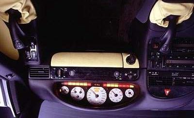
braking. The Daimler-Chrysler R129® (e.g. [47], fig.23) features instead a pure joystick based pilot
interface, unifying in a single device the whole set of main commands; the 2 joysticks actually present
provide redundancy and leave the pilot the choice of which hand to use for driving, but their positions
Fig.22 - "Filo" panel [43] Fig.24 - "R129" panel [46]
Fig.21 - Tractor control panel [50] Fig.23 - "C-Cross" panel [46] Fig.25 - "Hy-Wire" panel [52]
EPE 2003 - Toulouse ISBN : 90-75815-07-7 P.13You can also read