TECHNOLOGY HIGHLIGHTS - 2015 SCIENCE MISSION DIRECTORATE - NASA Technical Reports Server
←
→
Page content transcription
If your browser does not render page correctly, please read the page content below
National Aeronautics and Space Administration

                                                2015
                                                SCIENCE MISSION DIRECTORATE

                                                TECHNOLOGY
                                                HIGHLIGHTS
INTRODUCTION                                                                   4

TECHNOLOGY DEVELOPMENT                                                         7
    Starshade to Enable First Images of Earth-sized Exoplanets                 7
    WFIRST Coronagraph: Imaging Giant Exoplanets Around Nearby Stars           8
    Specialized Weaving Techniques Enable a New Heatshield for
    Planetary Exploration                                                      9
    Test Flights Demonstrate New Concept for Ocean Color Retrieval             10
    New Atmospheric Detector Technology Demonstrated on a CubeSat              11
    Laboratory Technology Helps Unlock the Mysteries of Magnetic Reconnection 11
    First Flights for CO2-detecting Lidar                                      13
    Sounding Rocket Mission Demonstrates New Technology to Measure
    Magnetic Fields in a Critical Region of the Sun’s Atmosphere               13
    Auto-Gopher: Drilling Deep to Explore the Solar System                     15
    Radial Core Heat Spreader to Improve Stirling Radioisotope
    Generator Heat Rejection                                                   16
    NASA Investigates a Backup Cooling Device for Stirling
    Radioisotope Power Systems                                                 17
    Measuring Snow to Manage Water Resources                                   18

TECHNOLOGY INFUSION                                                            19
    Seven SMD-supported Instruments to Search for Evidence of Life on Europa   19
    New Heat Shield to Protect Mission to the Sun                              22
    Game-changing Balloon Technology Enables Near-global Flight                23
    Earth Venture Suborbital-2 Awards Include SMD-sponsored
    Technology Infusions                                                       24
    Mapping Hydrogen to Locate Water on the Moon                               26
    Tiny Thrusters Demonstrate a Capability Needed to Detect
    Gravitational Waves                                                        27
    Computing Advances to Enable Speedy New Rover on the Red Planet            27
    New Technologies Enable Study of Magnetic Reconnection in Space            28
    New System Put Into Service to Process Nepal Earthquake Data               30

APPENDIX A. THE SMD TECHNOLOGY
DEVLOPMENT STRATEGY                                                            31

ACRONYMS                                                                       34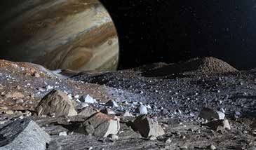
INTRODUCTION

NASA missions in all four science areas have benefitted from SMD technology development investments. Clockwise from top left: the Soil Moisture Active Passive (SMAP) spacecraft,
Mars Science Laboratory Curiosity Rover, Kepler, Magnetospheric Multiscale (MMS) mission.

The role of the Science Mission Directorate (SMD) is to                                         SMD DIVISION FUNDAMENTAL
enable NASA to achieve its science goals in the context                                         SCIENCE QUESTIONS
of the Nation’s science agenda. SMD’s strategic decisions
                                                                                                HELIOPHYSICS
regarding future missions and scientific pursuits are guided
by Agency goals, input from the science community—                                              • What causes the Sun to vary?
including the recommendations set forth in the National                                         • How do the geospace, planetary space environments and the
                                                                                                  heliosphere respond?
Research Council (NRC) decadal surveys—and a
                                                                                                • What are the impacts on humanity?
commitment to preserve a balanced program across
the major science disciplines. Toward this end, each of                                         EARTH SCIENCE
the four SMD science divisions—Heliophysics, Earth
                                                                                                •   How is the global Earth system changing?
Science, Planetary Science, and Astrophysics—develops                                           •   What causes these changes in the Earth system?
fundamental science questions upon which to base future                                         •   How will the Earth system change in the future?
research and mission programs. Often the breakthrough                                           •   How can Earth system science provide societal benefit?
science required to answer these questions requires
                                                                                                PLANETARY SCIENCE
significant technological innovation—e.g., instruments or
platforms with capabilities beyond the current state of the                                     • How did our solar system form and evolve?
art. SMD’s targeted technology investments fill technology                                      • Is there life beyond Earth?
                                                                                                • What are the hazards to life on Earth?
gaps, enabling NASA to build the challenging and complex
missions that accomplish groundbreaking science.                                                ASTROPHYSICS

                                                                                                • How does the universe work?
                                                                                                • How did we get here?
                                                                                                • Are we alone?

4 | 2015 SMD Technology Highlights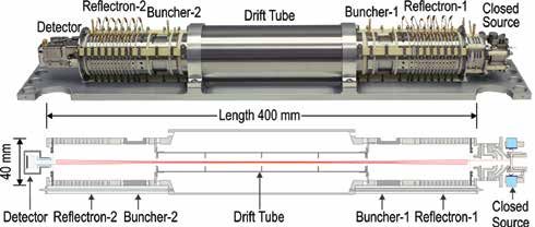
The directorate works to ensure that NASA actively            NASA TECHNOLOGY READINESS LEVEL
identifies and invests in the right technologies at the
                                                              (TRL) DEFINITIONS
right time to enable the Agency’s science program. SMD
                                                              Source: NPR 7123.1B, NASA Systems Engineering Processes and Requirements.
technology development is part of a comprehensive
Agency-wide strategy that involves coordination with          NASA
                                                                          DEFINITION
the NASA Chief Technologist and other Agency mission          TRL
directorates. This coordination helps ensure that
crosscutting technology development needs are identified      1           Basic principles observed and reported
across the Agency and that there is optimal return on
investments to fulfill those needs. SMD accomplishes
                                                              2           Technology concept and/or application formulated
technology development through technology programs
established in each of its four science divisions. (See
                                                                          Analytical and experimental critical function and/or
table on page 6 for a list of SMD technology development      3           characteristic proof-of-concept
programs.) If a technology development effort reaches
a NASA Technology Readiness Level (TRL) that is high                      Component and/or breadboard validation in laboratory
                                                              4
enough, it may be infused into an SMD flight program                      environment.
and targeted for further maturation, enabling its use
for a specific mission application. In some cases, other                  Component and/or breadboard validation in relevant
                                                              5           environment.
programs within SMD (e.g., the Astrophysics Division’s
Scientific Balloon Program and the Planetary Science                      System/sub-system model or prototype demonstration in a
Division’s Mars Exploration Program) sponsor technology       6           relevant environment.
development related to specific program objectives.
                                                                          System prototype demonstration in an operational
                                                              7           environment.
The subsequent chapters of this report highlight the most
significant SMD technology development efforts of 2015.
                                                                          Actual system completed and “flight qualified” through test and
The second chapter highlights technology achievements         8           demonstration.
that were sponsored by SMD technology development
programs in 2015. The third chapter briefly describes                     Actual system flight proven through successful mission
                                                              9           operations.
highlights from recent SMD technology infusions—SMD-
sponsored technologies that have been transferred to the
technology user (typically a flight mission) for refinement
and eventual application. Appendix A briefly reviews SMD’s
technology strategy and technology development process,
including the feedback loop that ensures the science
community both informs SMD technology investment
decisions and is informed about SMD technology
developments.

                                                                                                                      Introduction | 5
SMD TECHNOLOGY DEVELOPMENT PROGRAMS
EARTH SCIENCE DIVISION (FUNDED AND MANAGED THROUGH THE EARTH SCIENCE TECHNOLOGY OFFICE, ESTO)

Advanced Component Technologies
                                      Develops a broad array of components and subsystems for instruments and observing systems.
(ACT)

Instrument Incubator Program (IIP)    Funds innovative technologies leading directly to new Earth observing instruments, sensors and systems.

Advanced Information Systems
                                      Develops tools and techniques to acquire, process, access, visualize, and otherwise communicate Earth science data.
Technology (AIST)

In-Space Validation of Earth          Enables on-orbit technology validation and risk reduction for small instruments and instrument systems that could not
Science Technologies (InVEST)         otherwise be fully tested on the ground or airborne systems.

HELIOPHYSICS DIVISION

                                      Develops new sounding rocket and range technologies; serves as a low-cost testbed for new scientific techniques,
Sounding Rocket Program Office
                                      scientific instrumentation, and spacecraft technology eventually flown on satellite missions.

Heliophysics Technology and           Supports basic research of new technologies and feasibility demonstrations that may enable future science missions. Also
Instrument Development for            supports science investigations through suborbital flights that often involve a significant level of technology
Science (H-TIDeS)                     development.

PLANETARY SCIENCE DIVISION

Planetary Instrument Concepts for
                                      Funds the development of low-TRL technologies (TRL 1-4) leading directly to the development of new Planetary Science
the Advancements of Solar System
                                      observing instruments, sensors and in situ systems.
Observations (PICASSO)

Maturation of Instruments for Solar   Matures innovative instruments, sensors, and in situ system technologies (TRL 3-6) to the point where they can be
System Exploration (MatISSE)          successfully infused into new Planetary Science missions.

Homesteader                           Advances Planetary Science technologies in advance of New Frontiers Announcements of Opportunity.

Planetary Science and Technology
                                      Provides instrument technology development coupled with systems-level field tests.
through Analog Research (PSTAR)

Radioisotope Power                    Strategically invests in nuclear power technologies to maintain NASA’s current space science capabilities and enable
Systems Program                       future space exploration missions.

ASTROPHYSICS DIVISION

                                      Supports basic research of new technologies (TRL 1-3) and feasibility demonstrations that may enable future science
Astrophysics Research and
                                      missions. Also supports science investigations through suborbital flights that often involve a significant level of technology
Analysis (APRA)
                                      development.

                                      Develops mid-TRL technologies (TRL 3-6). Each focused Astrophysics program manages an SAT element separate from
Strategic Astrophysics Technology
                                      flight projects: Technology Development for Physics of the Cosmos (TPCOS), Technology Development for Cosmic Origins
(SAT)
                                      Program (TCOR), and Technology Development for Exo-Planet Missions (TDEM).

                                      Provides opportunities for early-career astrophysics technologists to develop the skills necessary to lead astrophysics
Roman Technology
                                      flight instrumentation development projects, and fosters career development by providing incentives to help achieve long-
Fellowships Program
                                      term positions. Develops innovative technologies that enable or enhance future astrophysics missions.

6 | 2015 SMD Technology Highlights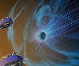
TECHNOLOGY DEVELOPMENT
STARSHADE TO ENABLE FIRST IMAGES OF                                                           Impact: The starshade and the coronagraph (also
EARTH-SIZED EXOPLANETS                                                                        known as an internal occulter) are the two technologies
Technology Development: Currently, astronomers can                                            NASA intends to advance to enable the first image of an
investigate Earth-sized exoplanets using only indirect                                        Earth-like planet (for more information on coronagraph
methods such as detecting the changes in starlight as                                         technology, see the entry on the Wide-Field Infrared
a planet passes in front of its star. The starshade (also                                     Survey Telescope [WFIRST] coronagraph on page 8).
known as an external occulter) is a spacecraft that will                                      Achieving the detection sensitivities required to image exo-
enable telescopes in space to take pictures of planets                                        Earths and look for evidence of life in their atmospheres
orbiting faraway stars. The starshade is designed to fly                                      is very difficult. Researchers do not know enough at this
in front of a telescope and block the immense glare from                                      time to decide which approach will be more successful, so
a star’s light before it enters the telescope, allowing the                                   it is advantageous for NASA to pursue both technologies
planet’s reflected light to pass through and be collected.                                    to learn more. By blocking a star’s light outside of the
Models predict the starshade can achieve the required                                         telescope, rather than on the inside, the starshade concept
10 -10 contrast levels required to detect Earth-sized planets                                 significantly reduces the cost and complexity of the trailing
in the habitable zones of their stars. To successfully                                        telescope. In fact, the starshade is compatible with any
achieve starlight blocking, the starshade must unfurl and                                     type of future visible and near infrared telescope mirror—an
expand in space to almost the size of a baseball diamond                                      on-axis monolith like the 2.4-m WFIRST or a large multi-
(34 m diameter). The starshade’s razor-sharp petals re-                                       segmented mirror like the 10-m-class Large Ultra-Violet
direct the effects of diffraction—the bending of starlight                                    Optical Infrared (LUVOIR) concept. The starshade also
around the petal edges producing unwanted glare—and                                           offers the opportunity to be launched separately, and can
create a dark shadow for the trailing telescope to fly in.                                    potentially rendezvous at a later date with any starshade-
The starshade and telescope are separated by as much as                                       compatible telescope.
50,000 km—almost four Earth diameters.
                                                                                              Status and Future Plans: Scaled prototypes of the
                                                                                              starshade petals, expandable inner disk, and opaque
                                                                                              origami shield have already been produced through NASA-
                                                                                              funded SAT awards to Princeton University and JPL teams.
                                                                                              Optical demonstrations by Principal Investigators (PIs) from
                                                                                              industrial partner Northrop Grumman were conducted in
                                                                                              2015 across a 2-km stretch of dried lake bed in the Nevada
                                                                                              desert. These demonstrations have helped engineers
                                                                                              understand the starshade’s capabilities. A second optical
An artist’s depiction of the fully-deployed starshade spacecraft (left) next to the space     demonstration effort began in 2015 with the assembly of
telescope it supports. The two spacecraft must fly in almost perfect alignment to allow the   an enclosed 78-m testbed at Princeton University; first light
telescope to stay in the shadow created by the starshade.
                                                                                              is scheduled for the spring of 2016.

                                                                                                                           Technology Development | 7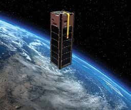
Coronagraph (SPC) and a Hybrid Lyot Coronagraph
                                                                                           (HLC). All three of WFIRST’s CGI technology milestones
                                                                                           for 2015 were passed successfully. First, the HLC
                                                                                           demonstrated a raw contrast (speckle/star intensity ratio)
                                                                                           of 10 -8, using a 10% bandwidth filter in visible light (550
                                                                                           nm), in a static environment. Second, the SPC achieved
                                                                                           the same milestone under the same conditions. For both
                                                                                           the HLC and SPC, the figure above shows excellent
                                                                                           average contrast (blue-green) over most of the field of
A 10-m prototype of the starshade’s inner disk is demonstrated at NASA’s Jet Propulsion    view, and slight turn-up (red) at the inner and outer radii,
Laboratory.
                                                                                           as expected. The third milestone was accomplished when
                                                                                           the Low Order Wavefront Sensing and Control (LOWFS)
Sponsoring Organization: This technology is currently                                      subsystem achieved its goal of providing sensing of
being funded through the Astrophysics Division’s SAT                                       pointing jitter and control at the 0.4 milli-arc-second root-
program and Exoplanet Exploration Program. The                                             mean-square (RMS) level, which will keep a target star
starshade development effort is led by NASA JPL, PI                                        sufficiently centered on the coronagraph star-blocking
Jeremy Kasdin at Princeton University, and PI Tiffany                                      mask, when the WFIRST telescope experiences pointing
Glassman at Northrop Grumman Corporation.                                                  drift and jitter.

WFIRST CORONAGRAPH: IMAGING GIANT
EXOPLANETS AROUND NEARBY STARS
Technology Development: The Wide-Field Infrared
Survey Telescope (WFIRST) is the highest-ranked
recommendation for a large space mission in the NRC                                        Pupil-plane reflective mask for the SPC, 24-mm diameter, black silicon on mirror (left).
                                                                                           Image-plane reflective mask for the back-up technology Phase Induced Amplitude
2010 decadal survey, New Worlds, New Horizons (NWNH)                                       Apodization Complex Mask Coronagraph (PIAA-CMC) coronagraph, 155-μm diameter,
in Astronomy and Astrophysics. The WFIRST coronagraph                                      raised elements on silicon (center). Image-plane transmitting mask for HLC, 100-μm
                                                                                           diameter, raised dielectric and metal on glass (right). All masks were fabricated in the
instrument (CGI) will be the first high-contrast stellar                                   Micro-Devices Lab (MDL) at the Jet Propulsion Laboratory (JPL).
coronagraph in space. It will enable WFIRST to respond
to the goals of NWNH by directly imaging and spectrally                                    Impact: With achievement of these milestones, NASA
characterizing giant exoplanets similar to Neptune and                                     is a major step closer to being confident that WFIRST
Jupiter, and possibly even super-Earths (extrasolar planets                                will be able to directly image planets and dust disks
with a mass higher than Earth’s but lower than our Solar                                   around nearby stars. There are at least 15 radial-velocity
System’s ice giants, Neptune and Uranus), around nearby                                    exoplanets that both coronagraphs will be able to image
stars. The WFIRST CGI includes both a Shaped Pupil                                         in their dark hole regions, in a few hours integration time
                                                                                           each. The WFIRST coronagraph will enable scientists to
                                                                                           see these exoplanets directly for the first time, and the
                                                                                           images will be in their true colors (using some of the other
                                                                                           color filters in the CGI). A simulation is shown in the figure
                                                                                           on page 9, where the blocked star is hidden inside the
                                                                                           annulus; a planet is seen at about 5 o’clock, and the star
                                                                                           is assumed to have no zodiacal dust around it (left) or a
                                                                                           strong dust cloud (right).

                                                                                           Status and Future Plans: WFIRST successfully
                                                                                           completed its Mission Concept Review in December 2015,
Measured milestone contrasts for the HLC (middle) and SPC (left) in a vacuum testbed in
2015, where the milestone target contrast of 10 -8 average in the dark hole (the annular   in preparation for its Phase-A start the following January
and wedge-shaped regions, respectively) was achieved for both coronagraphs, as planned     (which was also successful). The CGI is baselined as a
and on schedule.
                                                                                           technology demonstration instrument on WFIRST; it does

 8 | 2015 SMD Technology Highlights
not drive mission requirements beyond those needed
for the Wide Field Instrument. However, with one year of
allocated observing time out of a six-year mission, NASA
expects that it will achieve breakthrough science, and
will demonstrate key technology elements for follow-up
missions, the next of which could be aimed at finding
                                                                                           A drawing of the individual components that make up a heatshield (left) and the fully
habitable Earth-like planets around nearby stars.
                                                                                           assembled heatshield with integrated seams bonded to the structure underneath (right).

                                                                                           shields. To respond to this need, NASA and its industry
                                                                                           partners are developing an innovative way to design and
                                                                                           manufacture a family of ablative thermal protection system
                                                                                           (TPS) materials using commercially available weaving
                                                                                           technology. This new approach—called Heat-shield
                                                                                           for Extreme Entry Environment Technology (HEEET)—
                                                                                           leverages the way three-dimensional (3-D) weaving is used
                                                                                           to manufacture aircraft parts made of carbon composite
Simulation of expected image with CGI on WFIRST of a planet (at about 5 o’clock) with no   materials. To manufacture TPS materials with the desired
zodiacal dust cloud (left) and with a zodiacal dust cloud (right).
                                                                                           properties, fibers of different compositions and variable
                                                                                           yarn densities are accurately placed in a 3-D structure.
Sponsoring Organization: This coronagraph technology                                       Three-dimensional weaving extends the traditional two-
is jointly funded by the Astrophysics Division’s SAT                                       dimensional (2-D) weaving by interconnecting woven
program, in partnership with the NASA Space Technology                                     material in the third direction, enabling the manufacturing
Mission Directorate (STMD). NASA JPL currently leads the                                   of materials that are more robust to the entry environment
coronagraph development effort, and key contributions of                                   than traditional 2-D woven materials. The panels are then
the coronagraph team have been provided by three former                                    infused with resins and cured to lock the fibers in place.
SAT PIs: Jeremy Kasdin at Princeton University, John                                       Using advanced modeling, design, and manufacturing
Trauger at NASA JPL, and Olivier Guyon at the University                                   tools to optimize the weave for overall improved
of Arizona.                                                                                performance, the HEEET project has manufactured a new
                                                                                           family of TPS materials and tested them for a wide variety
                                                                                           of entry conditions.
SPECIALIZED WEAVING TECHNIQUES ENABLE
A NEW HEATSHIELD FOR PLANETARY                                                                                               Impact: Depending on the mission
EXPLORATION                                                                                                                  design, peak heat-flux during entry
Technology Development: When the Galileo mission’s                                                                           can reach about 10,000 W/cm2 for
probe entered the Jovian atmosphere in December 1995,                                                                        both Venus and Saturn, and the
it experienced temperatures twice as hot as the surface of                                 A multi-layer weave schematic     peak pressure can range up to
                                                                                           showing high-density top and
the sun, and required carbon phenolic shields to protect its                               bottom layers with a mid-
                                                                                                                             about 1,000 kPa. HEEET is currently
onboard payload from the intense heat. Since that mission,                                 density layer with different yarn being designed to withstand these
                                                                                           composition.
NASA has not flown a spacecraft that required protection                                                                     conditions and at the same time
from such extreme heat. Recently, however, the NRC                                         provide mass efficiency far superior to that of the heritage
Planetary Science Decadal Survey has recommended                                           carbon phenolic material used for TPS in legacy missions.
that NASA consider in situ science missions to Venus and                                   In addition to providing thermal protection, the 3-D weave
Saturn as a high priority in the New Frontiers competed                                    also increases the mechanical robustness of the TPS
mission set. To reach the surface of these planets,                                        material.
missions will require heatshields that are capable of
withstanding very extreme entry environments, but are not
as heavy as the previously used carbon phenolic heat

                                                                                                                                      Technology Development | 9
Status and Future            technology enables faster revisit times compared to
                                           Plans: The HEEET team        traditional spectrometer concepts—all with an instrument
                                           is currently supporting      that is smaller and 3-4 times lighter than previous sensors.
                                           multiple New Frontier        The technology used to develop MOS could dramatically
                                           proposals in anticipation    reduce payload size and mission risk for a geostationary
                                           of a New Frontiers           mission.
                                           Announcement of
                                           Opportunity at the end of
Testing of HEEET material at the NASA Ames 2016. Plans call for the
Arc Jet Complex in the Interaction Heating HEEET project to mature
Facility.
                                           and deliver technology
                                           for infusion into selected
missions long before Key Decision Point B—the decision
gate leading to the period in the mission lifecycle where a
project begins preliminary design and completes required
technology development. In 2015, HEEET milestones
included demonstration of the ability to form and resin-                The MOS instrument installed in the Twin Otter aircraft. (Credit: Tim Valle, Ball Aerospace)
infuse a representative acreage HEEET tile, the spherical
nose cap. In addition, the project successfully completed               Impact: MOS was designed and developed to provide
an arc jet test series to support material response model               a small coastal imaging spectrometer that would meet
development and in support of the seam design. This                     the projected measurement requirements of the NASA
testing allowed the project to refine its material response             GEOstationary Coastal and Air Pollution Events (GEO-
model in support of TPS sizing and to narrow the seam                   CAPE) mission concept. One objective of GEO-CAPE
design trade space.                                                     is to help scientists discern the dynamics of coastal
                                                                        ecosystems, river plumes, and tidal fronts. Coastal regions
Sponsoring Organization: SMD funding of HEEET                           experience numerous effects from human activities—
began in 2013, when the Planetary Science Division                      materials enter the ocean from the land and atmosphere,
(PSD) jointly funded a year-long formulation study with the             and a disproportionate amount of the world’s seafood is
Space Technology Mission Directorate’s Game Changing                    harvested from the coastal ocean regions. Technologies
Development (GCD) Program. In fiscal year (FY) 14, the                  developed for MOS will enable a GEO-CAPE sensor that
HEEET project was formally funded jointly by SMD and                    can accurately and quickly image these important coastal
STMD, as a four-year effort to further mature technology                regions to help scientists understand and model the way
for advanced TPS. NASA’s industry partners include Bally                these regions respond to phenomena such as storms,
Ribbon Mills in Bally, Pennsylvania and Fiber Materials Inc.            harmful algal blooms, hazardous spills, and flooding.
in Biddeford, Maine.
                                                                        Status and Future Plans: MOS conducted a series of
                                                                        engineering flight tests in October 2014 onboard a Twin
TEST FLIGHTS DEMONSTRATE NEW CONCEPT                                    Otter aircraft. The flights, totaling up to 26 hours, were
FOR OCEAN COLOR RETRIEVAL                                               conducted over Lake Tahoe and the Sacramento and
Technology Development: The Multi-Slit Optimized                        San Joaquin rivers and included some over-flights of
Spectrometer (MOS) prototype instrument is an airborne                  in situ (boat-based) water quality measurements. Work
sensor designed to demonstrate and validate the multi-                  on MOS concluded in August 2015, following extensive
slit concept for hyperspectral ocean color retrievals with              data analysis. Looking forward, the MOS project team
real-world scenes. The instrument design represents a                   hopes to add a polarimeter to the system to demonstrate
new option for hyperspectral sensing: MOS multiplexes                   simultaneous characterization of aerosols above coastal
a scene by imaging from four slits at the same time.                    scenes.
This method allows the MOS sensor to cover the field of
regard four times faster than a single slit spectrometer,
while achieving the same signal-to-noise ratio. This new

10 | 2015 SMD Technology Highlights
Poly-PicoSatellite Orbital Deployer (P-POD) mounted on
the upper stage of the Delta II rocket about 107 minutes
after launch. Amateur radio collaborators in Europe were
the first to detect the GRIFEX signal beacon about two
hours after release. GRIFEX was put into an approximately
650 km circular, polar, low Earth orbit with a 95-minute
orbit period.
Impact: The GRIFEX project has fully demonstrated a
key technology that will enable hourly, high-resolution
spatial and spectral measurements of rapidly changing
An airborne view of Lake Tahoe during an MOS test flight. atmospheric chemistry and pollution transport from a
geostationary orbit. The ROIC will enable development
Sponsoring Organization: The Earth Science Division of all-digital FPAs capable of the high-speed imaging
sponsored development of MOS via the IIP. PI Tim Valle needed to observe the rapidly evolving conditions in the
of Ball Aerospace and Technologies Corp. led the MOS troposphere. This capability is relevant to the study of
development effort. climate change, as well as for future missions such as
GEO-CAPE that require advanced detectors.
NEW ATMOSPHERIC DETECTOR TECHNOLOGY Status and Future Plans: The GRIFEX team reported
DEMONSTRATED ON A CUBESAT complete, successful demonstration of the GRIFEX ROIC/
Technology Development: detector in the space environment within the first six
The GEO-CAPE ROIC In- months of operation. As of this report, the spacecraft is
Flight Performance still healthy and operational and is expected to continue
Experiment (GRIFEX) CubeSat sending data for many months to come.
was launched from
Vandenberg Air Force Base Sponsoring Organization: The
on Saturday, January 31, Earth Science Division provided
2015, as an auxiliary payload funding to develop the ROIC
to the Soil Moisture Active technology used on GRIFEX via a
Passive (SMAP) mission. 2008 ESTO ACT program investment.
GRIFEX is a 3-unit (3U, David Rider at the NASA Jet
10x10x30 cm) CubeSat The GRIFEX ROIC focal plane Propulsion Laboratory and James
array. (Image credit: D. Rider,
designed to verify the JPL/Caltech) Cutler at the University of Michigan
performance of a new currently lead the GRIFEX team.
spaceborne technology to
study conditions in Earth’s
An artist’s depiction of GRIFEX in orbit.
atmosphere. GRIFEX includes LABORATORY TECHNOLOGY HELPS
a state-of-the-art readout integrated circuit (ROIC)/Focal UNLOCK THE MYSTERIES OF MAGNETIC
Plane Array (FPA) with in-pixel digitization and an RECONNECTION
unprecedented frame rate of 16 kHz. Intended for future Technology Development: Technological progress in
imaging interferometry instruments and missions, the recent years has significantly increased the ability to
technology specifically targets the requirements of the generate, control, and diagnose plasmas in the laboratory,
GEOstationary Coastal and Air Pollution Events (GEO- allowing researchers to reliably reproduce important
CAPE) mission. GEO-CAPE was recommended by the processes widely observed in space. The Magnetic
NRC’s Earth Science Decadal Survey to investigate the Reconnection Experiment (MRX) is enabling scientists
physical, chemical, and dynamical processes that to understand several of these important phenomena,
determine the composition and air quality of Earth’s including the magnetic reconnection process and the
troposphere. GRIFEX was released into space by a behavior of solar magnetic loops—known as flux ropes.
Technology Development | 11The magnetic reconnection process efficiently converts Impact: Magnetic reconnection underlies most of the
magnetic energy to plasma particle energy explosive phenomena observed in heliophysics, including
solar flares, coronal mass ejections (CME), solar wind
interaction with planetary magnetospheres, magnetic
disturbances observed in Earth’s magnetosphere,
and particle energization in the outer heliosphere.
Reconnection also plays a key role in many astrophysical
phenomena ranging from star formation to accretion
onto supermassive black holes. However, many critical
questions, such as why reconnection always occurs
Image of magnetic loops (flux ropes) on the sun, captured by NASA’s Solar Dynamics impulsively fast and what are conditions for CMEs to
Observatory (SDO).
initiate, remain unanswered despite decades of active
research. Use of laboratory experiments in conjunction
The magnetic reconnection process efficiently converts with satellite observations and numerical modeling
magnetic energy to plasma particle energy through has enabled breakthroughs in understanding. MRX
topological changes in the magnetic field. MRX allows measurements have confirmed and validated the
researchers to generate the process of magnetic interpretation of results from the Polar and Cluster
reconnection in a controlled manner by pulsing electric satellites, whose observations were necessarily limited
currents in coils inside a vacuum chamber. The to a few spatial points. Measurements from MRX will
time evolution of magnetic field vectors and plasma also enable researchers to use data from the new
parameters are measured in the MRX chamber at a large Magnetospheric Multiscale (MMS) mission to identify
number (typically several hundreds) of locations. These the predicted electron diffusion regions wherein field
measurements have enabled scientists to characterize lines actually reconnect. The in situ magnetic field
several aspects of the magnetic reconnection process, measurements from the MRX flux rope experiment
including the accurate determination of current sheet demonstrated a promising way to understand the initiation
structures, the reconnection rate, waves and turbulence, mechanisms of CMEs and enhance space weather
and the energy conversion process. To study the eruption research.
of magnetic loops, researchers use MRX to generate
magnetic flux ropes between electrodes in a modified coil Status and Future Plans:
setup. By slowly injecting a sufficiently large magnetic free NASA will leverage
energy, the flux ropes can rapidly erupt via a large-scale investments in physics
instability. Both point-like and large-scale measurements laboratory technology like
of the flux ropes and associated phenomena generated in MRX not only to
MRX enable researchers to characterize the behavior of understand the science
flux ropes over a wide range of parameters. from its current missions,
but to guide the science
targeted in future missions.
Technology advances from
MRX will also contribute to
the next-generation Facility
The FLARE device, currently under for Laboratory
construction. Reconnection Experiments
(FLARE) device, scheduled for operation in 2017. FLARE is
being proposed as a user facility for collaborative research
on magnetic reconnection and related explosive
Photo of a hydrogen plasma where magnetic reconnection is generated in MRX by two phenomena.
coils (blackened objects on the left and right), superimposed by reconnecting magnetic
field lines measured by in situ diagnostics.
12 | 2015 SMD Technology HighlightsSponsoring Organization: The Heliophysics Division’s facilitate a greater understanding of the role CO2 plays in
H-TIDeS program contributed funding to research on MRX, the global carbon cycle. The newly developed IPDA Lidar
which was conducted at Princeton University by PI, Dr. technology has the potential to provide satellite-based CO2
Hantao Ji. measurements that will deliver accurate CO2
measurements all day and night, year-round, at all
latitudes. These data will help identify human-generated
FIRST FLIGHTS FOR CO2-DETECTING LIDAR CO2 sources and sinks, improve climate models and
Technology Development: Nearly two decades of NASA climate predictions, and enable a better understanding of
technology investment in lidar systems and two-micron the connection between climate and CO2 exchange.
transmitters has resulted in a new capability for remotely
measuring the carbon dioxide (CO2) levels in Earth’s Status and Future Plans: Over 11 days in March 2015,
atmosphere. NASA has developed an Integrated Path the pulsed 2-micron direct detection IPDA Lidar completed
Differential Absorption (IPDA) Lidar that incorporates high- 10 engineering flights, totaling about 27 hours, over
energy, double-pulse lasers with high repetition rates. The Virginia onboard the NASA B200 King Air aircraft. The
compact lidar instrument aims to provide accurate, high- test flights occurred over diverse terrain with varying
resolution atmospheric CO2 column measurements from reflectivity, and analysis shows the measured optical depth
an airborne platform. The laser pulses can be tuned and for column length matched the modeled value within a
locked near the 2.05 micron wavelength, an ideal spectral few percent. Results from the tests are positive and the
region for CO2 sensing. Separated by 150 microseconds, instrument has likely performed the first proof-of-principle
the first pulse is tuned to a high CO2 absorption demonstration of an airborne, direct-detection, two-micron
wavelength and the second pulse to a low absorption CO2 measurement. Currently, the project team is working
wavelength. By aiming the pulses at a hard target, or to incorporate a third transmitted pulse into the system.
Earth, the difference between the return signals correlates A triple-pulsed system would enable simultaneous CO2
to the average amount of CO2 in the column between the and water vapor (H2O) measurements in a single compact
instrument and the target. instrument.
Impact: Carbon dioxide is Sponsoring Organization: The Earth Science Division
a greenhouse gas that is provided funding to develop the IPDA Lidar to PI Upendra
considered an important Singh at Langley Research Center via the IIP and ACT
contributor to global programs.
warming. Currently,
satellites monitoring
Earth’s CO2 levels employ SOUNDING ROCKET MISSION DEMONSTRATES
passive sensing NEW TECHNOLOGY TO MEASURE MAGNETIC
instruments. An active FIELDS IN A CRITICAL REGION OF THE SUN’S
sensing system like the ATMOSPHERE
IPDA Lidar has the Technology Development: Remote sensing of magnetic
potential to overcome fields requires both precision spectroscopy and precision
some of the limitations of polarimetry (spectro-polarimetry). NASA led an
passive systems to international team that developed the Chromospheric
The 2 micron IPDA lidar system installed provide the accuracy Lyman-Alpha Spectropolarimeter (CLASP)—the first
in the NASA B200. (Image credit: Upendra required to more instrument to achieve the spectro-polarimetry needed for
Singh)
definitively resolve the CO2 magnetic field measurements of the outer layers of the
profile. The IPDA Lidar is intended to be a stepping-stone solar atmosphere. Previous solar magnetic field
toward an eventual spaceborne mission for active remote measurements were restricted to regions near the sun’s
sensing of CO2, such as the ASCENDS (Active Sensing of surface because adequate spectro-polarimetry has been
CO2 Emissions over Nights, Days, and Seasons) mission (until now) technically feasible only in visible and near-
concept. Recommended by the National Research Council infrared light. In these regions, the forces associated with
in its 2007 decadal survey, ASCENDS is intended to gas pressure dominate the forces associated with
Technology Development | 13magnetic fields. However, measurements of the dominant force in these regions—
in the outer solar the magnetic fields. By achieving ultraviolet spectro-
atmosphere (the transition polarimetry in the transition region and corona, CLASP has
region and corona) the shown how to achieve direct magnetic field measurements
magnetic fields dominate. that will enable scientists to understand solar processes
Numerical extrapolation to that affect life on Earth.
determine magnetic fields
in the outer layers of the Status and Future Plans: CLASP launched from White
solar atmosphere (where Sands Missile Range aboard a NASA Sounding Rocket
magnetic pressure Program Black Brant IX vehicle on September 3, 2015.
dominates) from The flight attitude control system proved very stable during
observations of fields in the period of observations, with less than 0.1” jitter and
the photosphere (where 1” drift over the five minutes of data accumulation. The
gas pressure dominates) NASA-developed camera system achieved a six-electron
is not sufficiently accurate root mean square (RMS) noise during flight. The initial
to understand and predict data indicate that CLASP detected scattering polarization
key physical processes. in Lyman-alpha. Interpretation of these polarization
CLASP provided the first modulation observations in terms of the solar magnetic
measurement of the field and the implications for the theory of structures in
scattering polarization of the solar atmosphere is being prepared for publication
light in the Lyman-alpha in a peer-reviewed journal. Accomplishment of these
spectral line, Ultra-Violet challenging measurements provides a path to routinely
light that is formed in the obtaining magnetic field measurements of the solar
The international experiment team attending upper chromosphere and atmosphere from a future orbital platform.
the launch of the CLASP instrument (inside transition region of the
white box) mounted on the launch rail.
sun. This polarization is Sponsoring
modified by the local Organization: The
magnetic field; hence CLASP’s detection of this CLASP instrument is a
polarization is a powerful tool for measuring the magnetic partnership between
field in the upper chromosphere. The modification of the NASA; the Japan
linear polarization in the Lyman-alpha spectral line is small, Aerospace Exploration
only on the order of 0.5%. Measurement of this small Agency (JAXA); the
change in polarization requires a well calibrated instrument, National Astronomical
maintenance of stable pointing during the observations, as Observatory of Japan
well as low-noise cameras. The NASA CLASP team (NAOJ); the Instituto de
developed the low-noise CLASP camera system and an Astrofísica de Canarias
The quiet sun region observed by CLASP. This
accompanying flexible avionics package that can be image is taken with the NASA-developed slitjaw in Santa Cruz de
modified to accommodate other suborbital missions. camera with a broad band filter centered on the Tenerife, Spain (IAC);
Lyman alpha spectral line. The black line in the
image is the slit. and the Institut
Impact: Space weather—the dynamic electrical d’Astrophysique Spatiale
and magnetic conditions in the Earth’s outer space in Paris (IAS). The optical instrument was developed, built
environment—can greatly affect human endeavors, and calibrated by NAOJ. The Heliophysics Division’s
disrupting electric power grids on Earth, interfering H-TIDeS low-cost access to space (LCAS) program
with high-frequency radio communications and Global provided funding for NASA’s contribution to CLASP, which
Positioning System (GPS) navigation systems, and was developed by PI, Dr. Amy Winebarger, at Marshall
damaging Earth-orbiting spacecraft. Most of the solar Space Flight Center (MSFC).
variability and solar eruptions affecting space weather
originate in the sun’s outer atmosphere regions. Therefore,
to understand space weather it is critical to achieve direct
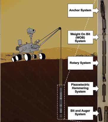
14 | 2015 SMD Technology HighlightsAUTO-GOPHER: DRILLING DEEP TO EXPLORE recommended that NASA explore three solar system
THE SOLAR SYSTEM bodies with accessible aqueous regions: Mars; Jupiter’s
Technology Development: moon, Europa; and Saturn’s moon, Enceladus. Each of
The ability to penetrate these bodies poses different drilling-related challenges.
subsurfaces and collect Drilling on Mars requires penetrating dry rock and regolith
pristine samples from that have physical properties (i.e., tensile strength,
depths of tens of meters to hardness, etc.) that can vary many orders of magnitude
kilometers is critical for though the drill depth. A drill on Enceladus and Europa will
future exploration of bodies need to operate in ice at temperatures below 100 K, while
in our solar system. SMD is accounting for the low gravity on Enceladus or the high
supporting development of surface radiation on Europa. The Auto-Gopher must be
a deep-drill sampler called designed to achieve its goals of penetrating the subsurface
the Auto-Gopher for to great depths, capturing pristine samples, and delivering
potential deployment in those samples to onboard instruments for analysis or
future space exploration for potential sample return—all in the harsh conditions
missions. The Auto-Gopher encountered in space.
employs a piezoelectric
actuated percussive
mechanism for breaking
An initial version of the drill technology—the formations and an electric
Auto-Gopher-1—is pictured here with cores
it acquired from drilling a 3-m hole in 40 motor to rotate the drill bit
MPa gypsum. and capture powdered
cuttings. It incorporates a wireline architecture; the drill is
suspended at the end of a small diameter tether that
provides power, communication, as well as structural
support needed for lowering and lifting the drill out of the
borehole. Thanks to this unique architecture, the maximum
drilling depth is limited only by the length of the tether. The
wireline operation used on the Auto-Gopher removes one
of the major drawbacks of traditional continuous drill string
systems—the need for multiple drill sections that can add
significantly to the mass and the complexity of a deep drill.
As such, the Auto-Gopher system mass and volume can
be kept quite low for shallow or deep holes. While drilling,
numerous sensors and embedded instruments can
perform in situ analysis of the borehole wall. Upon
reaching a preset depth, the drill is retracted from the
borehole, the core and/or cuttings are removed for detailed
Illustration of the Auto-Gopher concept as a wireline deep drill.
analysis by onboard instruments, and the drill is lowered
back into the hole to continue the penetration process.
Status and Future Plans: The aim of the Auto-Gopher
Impact: The Auto-Gopher is intended to help scientists development effort is to demonstrate a scalable
answer one of the most pressing questions in science: technology that makes deep drilling possible using current
Has life ever existed anywhere else in the universe? Since launch vehicles and power sources. This technology
water is a critical prerequisite for life, as we know it, NASA development has been accomplished in several
exploration missions are targeting bodies in the solar generations including the Ultrasonic/Sonic Driller/Corer,
system that are known to have or have had flowing liquid Ultrasonic/Sonic Gopher, and the Auto-Gopher-1. In 2015,
water. The latest Planetary Decadal Survey (Vision and PSD awarded a project under its MatISSE program to
Voyages for Planetary Science in the Decade 2013-2022) support the next generation of Auto-Gopher technology
Technology Development | 15development—the Auto-Gopher-2. In 2015, the project The RCHS is a hollow, dimpled titanium disc that uses
produced a core breaker and retaining mechanism and boiling and condensing water to transfer heat radially from
demonstrated their operation. This latest drill is also being the center where the Stirling convertor would be located,
designed to house electronics, sensors, and mechanisms to the outer diameter where the generator housing would
needed for autonomous drilling, and the critical attach. The experimental RCHS weighs about 175 grams
subsystems are currently being breadboarded and tested. and is designed to transfer 130 W (thermal) from the hub to
Future planned activities include field trials to validate drill the perimeter. It operates at a nominal temperature of 90°C
operation in harsh conditions at a U.S. gypsum quarry with a usable range between 50 and 150°C. For testing,
(gypsum can change from hard crystalline gypsum, to soft the Stirling convertor was replaced by an electrical heating
sugar gypsum, to very hard anhydrite with numerous clay- element and the generator housing was replaced with a
rich veins) and inside a vacuum chamber, drilling in ice at heat absorber.
approximately -100°C.
Two parabolic flight
Sponsoring Organization: The research, led by PI Kris campaigns and one
Zacny of Honeybee Robotics, is funded by the PSD’s suborbital flight test
MatISSE program, and jointly developed with the Jet provided essential data in
Propulsion Laboratory (JPL)/California Institute of Technology. multiple gravity
environments to evaluate
the thermal performance
RADIAL CORE HEAT SPREADER TO IMPROVE of the RCHS. The
STIRLING RADIOISOTOPE GENERATOR HEAT parabolic flights took
REJECTION place during 2013 and
Technology 2014. The suborbital flight
Development: The NASA took place on July 7, 2015
Glenn Research Center is Black Brant IX Vehicle and included two RCHS
developing the next units, one parallel and one perpendicular relative to the
generation of Stirling launch vector. The Black Brant IX rocket delivered the
Radioisotope Generators RCHS payload to an altitude of 332 km with over eight
(SRGs) to power deep minutes of microgravity. The purpose of this experiment
space science missions. was to determine if the RCHS could function during all
One potential technology mission phases. Since SRGs are fueled and operating
gap is the waste heat prior to launch, it is crucial that proper thermal
rejection approach for management be maintained during 1-g ground handling,
higher power Stirling hyper-g launch, and micro-g space environments. Test
The Radial Core Heat Spreader shown convertors. The previous results verified that the RCHS could tolerate the
mounted inside the experiment heat
exchanger during preparations for the
140W Advanced Stirling gravitational transients throughout the suborbital flight,
suborbital flight test. Radioisotope Generator while transferring the thermal power necessary to keep a
(ASRG) used a copper Stirling convertor within its prescribed temperature limits.
alloy conduction flange to transfer heat from the convertor
to the generator housing radiator surface. The conduction Impact: The flight-tested RCHS is one-fourth the mass
flange would incur a substantial mass and thermal of the state-of-the-art ASRG copper conduction flange,
performance penalty for larger Stirling systems. The Radial and provides enhanced heat transfer to minimize thermal
Core Heat Spreader (RCHS) is a passive two-phase resistance. As the Stirling convertor’s power level
thermal management device developed to solve this issue increases, the mass savings and heat transport benefits
by using water vapor instead of copper as the heat provided by the RCHS will increase substantially. The
transport media. sounding rocket flight test proved that the RCHS could
maintain proper thermal control during hypergravity and
microgravity regardless of the orientation of the device
relative to the launch forces.
16 | 2015 SMD Technology HighlightsStatus and Future Plans: The RCHS has reached a under constant thermal heat input after the Stirling
Technology Readiness Level (TRL) of six for use in Stirling convertor was stopped for 90 minutes (long enough to
power systems through rigorous testing in a wide range reach steady-state temperatures). Additionally, the VCHP
of environments including launch, microgravity, and reliably and repeatedly activated through three convertor
thermal-vacuum. If the technology were adopted in the start/stop cycles.
next generation SRG, additional integrated system testing
would be required.
Sponsoring Organization: PSD’s Radioisotope Power
Systems Program sponsored the RCHS development
by providing funding to PI Marc Gibson at NASA Glenn
Research Center. The STMD Flight Opportunities Program
provided flight vehicles in partnership with the Reduced
Gravity Office (RGO) from the Johnson Space Center (JSC)
and NASA’s Sounding Rocket Program (NSRP) from the
Goddard Space Flight Center (GSFC) and Wallops Flight
Diagram of a Variable Conductance Heat Pipe prototype designed by Advance Cooling
Facility (WFF). Technologies, Inc. integrated with a free-piston Stirling convertor designed by Sunpower,
Inc. for test at NASA Glenn Research Center.
NASA INVESTIGATES A BACKUP COOLING Impact: The VCHP enables the ability to repeatedly stop
DEVICE FOR STIRLING RADIOISOTOPE POWER and restart Stirling convertor operation without risk of
SYSTEMS terminating the mission. This feature could be beneficial
Technology Development: NASA is sponsoring during installation of the GPHS modules into the Stirling
development of an alkali-metal Variable Conductance system, and during spacecraft integration and launch
Heat Pipe (VCHP) to serve as a heat source backup operations. Also, this feature improves mission flexibility
cooling device for Stirling Radioisotope Power Systems by enabling use of Stirling RPS for missions where
(RPS). RPS are critical to planetary missions because they scientific measurements require minimal electromagnetic
produce electricity and heat for long periods under the interference and vibration, which is achieved by temporarily
harsh conditions of deep space. In these systems, heat stopping convertor operation. The device could also allow
must be continuously removed from the plutonium-238 the system to recover from a temporary Stirling convertor
General Purpose Heat Source (GPHS) modules to maintain or electrical controller fault.
the modules and surrounding insulation at acceptable
temperatures. Past Stirling RPS prevented damage to the Status and Future Plans: The particular VCHP prototype
GPHS during an extended loss of cooling by spoiling the tested at GRC in April 2015 would raise the mass of a
insulation allowing the heat to escape—at the cost of early Stirling RPS by ~0.4 kg and increase the thermal loss by
termination of the system. In a Stirling RPS, an operating ~5 W. Plans for future development may include use of
Stirling convertor provides the necessary cooling as the improved materials for reduction of weight and thermal
GPHS heat is converted to electricity. However, there are losses, demonstration of system level operation in vacuum,
mission scenarios where it might be desirable to stop and demonstration under launch level vibration.
Stirling convertor operation. The VCHP is designed to
passively activate with a small increase in temperature and Sponsoring Organization: The Stirling VCHP backup
redirect heat from the GPHS to a secondary heat rejection cooling device was designed and fabricated under a
sink when the Stirling convertor is stopped. In April 2015, Phase III SBIR contract with funding from the PSD’s
a prototype VCHP developed by Advanced Cooling Radioisotope Power Systems Program’s Stirling Cycle
Technologies, Inc. through a Small Business Innovation Technology Development Project. The PI for this project
Research (SBIR) effort was successfully integrated with a is Dr. Calin Tarau from Advanced Cooling Technologies,
Stirling convertor and tested at NASA’s Glenn Research Inc. PSD is investigating Stirling RPS as a high-efficiency
Center (GRC). During this test, the prototype VCHP alternative to Radioisotope Thermoelectric Generators.
demonstrated its ability to passively maintain temperatures
Technology Development | 17MEASURING SNOW TO MANAGE WATER Status and Future Plans: In late February 2015,
RESOURCES WISM was installed on a Twin Otter aircraft for a series
Technology of demonstration flights over snow-covered areas of
Development: The Colorado. In 9.4 hours of total flight time, the WISM
Wideband (8-40 GHz) team collected high-resolution snow data over a broad
Instrument for Snow range of snowpack conditions near Grand Junction, CO,
Measurement (WISM) is particularly over an experiment site on Grand Mesa. To
The WISM instrument being integrated into the designed to accurately validate the WISM retrievals, extensive in situ snowpack
Twin Otter Aircraft. measure snowpack on profiles were also taken using high-resolution ground-
the ground from an airborne platform. WISM is comprised based radar and ancillary airborne lidar measurements.
of a dual-frequency (X- and Ku-bands) Synthetic Aperture These ground observations included 19 detailed snow
Radar (SAR) and a dual-frequency (K- and Ka-bands) pits (to determine snow density, temperature, grain size,
radiometer. Instead of using individual antenna feeds for grain type, and layer thickness profiles), 8,000+ manual
each frequency, WISM employs a broadband current sheet depth measurements, and measurements from two
array (CSA) antenna feed that enables the integration of snowmobile-based radars that profiled the entire WISM
the radar and radiometer using a single antenna aperture. flight line multiple times at 10-cm resolution. On this flight,
Use of this new technology is expected to achieve WISM demonstrated wideband antenna performance, as
improved snow measurements, along with significant size, well as near-simultaneous sensing with both the radar and
weight, and power advantages over previous systems. radiometer.
Impact: Seasonal snowpack supplies 50% to 80% of Sponsoring Organization: The Earth Science Division
the yearly water supply in the Western United States. provided funding for WISM to PI Tim Durham of Harris
To effectively manage water resources, frequent and Corporation via the IIP.
accurate measurements of the amount of water in the
snowpack—the snow water equivalent (SWE)—are critical
to understand the very small spatial scales over which
the snowpack varies. Eventually, the wideband antenna/
instrument technology demonstrated successfully by
WISM could be used in spaceflight applications to provide
improved measurements of SWE.
The Twin Otter carrying WISM gets a final checkout on the first day of flights.
18 | 2015 SMD Technology HighlightsTECHNOLOGY INFUSION
SEVEN SMD-SUPPORTED INSTRUMENTS TO because of chemical processes that occur as water and
SEARCH FOR EVIDENCE OF LIFE ON EUROPA rock interact at high temperatures. Europa’s potential
Technologies Infused: When NASA launches its mission liquid water, combined with its heat-producing geological
to explore Jupiter’s moon Europa in the 2020s, seven activity, make it one of the most promising places in the
instruments enabled by SMD technology investments or solar system to search for signs of present-day life. Seven
flight development efforts will be onboard to help achieve of the instruments that NASA recently selected to fly on
mission science goals. the Europa mission were enabled by SMD technology
investments or previous planetary mission investments
(see table on page 21). Two of those instruments—
MASPEX and REASON—are detailed below.
MASPEX: The MAss
Spectrometer for
Planetary EXploration/
Europa is a time-of-flight
(TOF) mass spectrometer
designed to determine the
Compiled from NASA’s Galileo spacecraft composition of Europa’s
Artist’s concept of NASA’s Europa mission spacecraft approaching its target for one of
data, this colorized surface image of Europa surface and subsurface
shows the blue-white terrains that indicate
many flybys. (Image credit: NASA/JPL-Caltech)
relatively pure water ice. Scientists are very ocean by measuring the
interested in these features because they may moon’s extremely tenuous
offer a way to investigate the habitability of the
The Europa mission will gather high-resolution images moon’s interior ocean. (Image credits: NASA/
atmosphere and any
of the moon’s surface, and investigate the composition JPL-Caltech/SETI Institute) surface material ejected
and structure of its interior and icy shell to determine if into space. MASPEX
the moon might be habitable for primitive forms of life. employs fast-switched dual reflectron ion optics to provide
Evidence from NASA’s Galileo mission in the 1990s high-mass resolution in a half-meter long instrument. This
strongly suggested that Europa may contain a vast ocean new technology enables mass resolution several orders of
underneath its icy crust. Europa also experiences great magnitude greater than previous mass spectrometers
tidal forces as it orbits Jupiter, and these forces cause the flown on NASA missions. MASPEX is also highly sensitive.
moon to flex, which produces heat in the moon’s interior. It can store over 100,000 ions and extract them at a rate of
Scientists also believe that Europa’s ocean is in direct 2 Khz, providing a very high throughput and high time
contact with its rocky interior, creating conditions that resolution. MASPEX’s storage capability, coupled with an
could be similar to geologically active places on Earth’s imbedded cryotrap that is more than 100,000 times more
sea floor, called hydrothermal zones. Hydrothermal zones sensitive than previous instruments, allows the analysis of
on Earth harbor large numbers of organisms that thrive trace organics at levels less that one part per billion and
Technology Infusion | 19You can also read