The enhanced X-ray Timing and Polarimetry mission-eXTP - IRIS UniPA
←
→
Page content transcription
If your browser does not render page correctly, please read the page content below
SCIENCE CHINA
                                               Physics, Mechanics & Astronomy                                                            print-crossmark

. Invited Review .                                                                                          February 2019 Vol. 62 No. 2: 029502
                                                                                                       https://doi.org/10.1007/s11433-018-9309-2
Special Issue: The X-ray Timing and Polarimetry Frontier with eXTP

        The enhanced X-ray Timing and Polarimetry mission—eXTP

        ShuangNan Zhang1* , Andrea Santangelo1,2* , Marco Feroci3,4* , YuPeng Xu1* , FangJun Lu1,
      Yong Chen1, Hua Feng5, Shu Zhang1, Søren Brandt36, Margarita Hernanz12,13, Luca Baldini33,
    Enrico Bozzo6, Riccardo Campana23, Alessandra De Rosa3, YongWei Dong1, Yuri Evangelista3,4,
Vladimir Karas8, Norbert Meidinger16, Aline Meuris10, Kirpal Nandra16, Teng Pan21, Giovanni Pareschi31,
        Piotr Orleanski37, QiuShi Huang22, Stephane Schanne10, Giorgia Sironi31, Daniele Spiga31,
       Jiri Svoboda8, Gianpiero Tagliaferri31, Christoph Tenzer2, Andrea Vacchi25,26, Silvia Zane14,
           Dave Walton14, ZhanShan Wang22, Berend Winter14, Xin Wu7, Jean J. M. in ’t Zand11,
Mahdi Ahangarianabhari29, Giovanni Ambrosi32, Filippo Ambrosino3, Marco Barbera35, Stefano Basso31,
     Jörg Bayer2, Ronaldo Bellazzini33, Pierluigi Bellutti28, Bruna Bertucci32, Giuseppe Bertuccio29,
      Giacomo Borghi28, XueLei Cao1, Franck Cadoux7, Riccardo Campana23, Francesco Ceraudo3,
    TianXiang Chen1, YuPeng Chen1, Jerome Chevenez36, Marta Civitani31, Wei Cui25, WeiWei Cui1,
  Thomas Dauser39, Ettore Del Monte3,4, Sergio Di Cosimo1, Sebastian Diebold2, Victor Doroshenko2,
            Michal Dovciak8, YuanYuan Du1, Lorenzo Ducci2, QingMei Fan21, Yannick Favre7,
             Fabio Fuschino23, José Luis Gálvez12,13, Min Gao1, MingYu Ge1, Olivier Gevin10,
            Marco Grassi30, QuanYing Gu21, YuDong Gu1, DaWei Han1, Bin Hong21, Wei Hu1,
  Long Ji2, ShuMei Jia1, WeiChun Jiang1, Thomas Kennedy14, Ingo Kreykenbohm39, Irfan Kuvvetli36,
             Claudio Labanti23, Luca Latronico34, Gang Li1, MaoShun Li1, Xian Li1, Wei Li1,
           ZhengWei Li1, Olivier Limousin10, HongWei Liu1, XiaoJing Liu1, Bo Lu1, Tao Luo1,
    Daniele Macera29, Piero Malcovati30, Adrian Martindale15, Malgorzata Michalska37, Bin Meng1,
     Massimo Minuti33, Alfredo Morbidini3, Fabio Muleri3,4, Stephane Paltani6, Emanuele Perinati2,
   Antonino Picciotto28, Claudio Piemonte28, JinLu Qu1, Alexandre Rachevski24, Irina Rashevskaya27,
       Jerome Rodriguez10, Thomas Schanz2, ZhengXiang Shen22, LiZhi Sheng20, JiangBo Song21,
                   LiMing Song1, Carmelo Sgro33, Liang Sun1, Ying Tan1, Phil Uttley9,
             Bo Wang17, DianLong Wang19, GuoFeng Wang1, Juan Wang1, LangPing Wang18,
     YuSa Wang1, Anna L. Watts9, XiangYang Wen1, Jörn Wilms39, ShaoLin Xiong1, JiaWei Yang1,
                Sheng Yang1, YanJi Yang1, Nian Yu1, WenDa Zhang8, Gianluigi Zampa24,
 Nicola Zampa24, Andrzej A. Zdziarski38, AiMei Zhang1, ChengMo Zhang1, Fan Zhang1, Long Zhang21,
              Tong Zhang1, Yi Zhang1, XiaoLi Zhang21, ZiLiang Zhang1, BaoSheng Zhao20,
                   ShiJie Zheng1, YuPeng Zhou21, Nicola Zorzi28, and J. Frans Zwart11

*Corresponding authors (ShuangNan Zhang, email: zhangsn@ihep.ac.cn; Andrea Santangelo, email: andrea.santangelo@uni-tuebingen.de; Marco Feroci,
email: marco.feroci@iaps.inaf.it; YuPeng Xu, email: xuyp@ihep.ac.cn)

⃝
c Science China Press and Springer-Verlag GmbH Germany, part of Springer Nature 2018                           phys.scichina.com   link.springer.com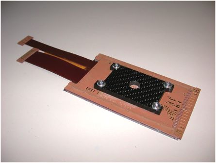
S. N. Zhang, et al. Sci. China-Phys. Mech. Astron.   February (2019)   Vol. 62   No. 2             029502-2

     1   Key Laboratory for Particle Astrophysics, Institute of High Energy Physics, Chinese Academy of Sciences, Beijing 100049, China;
                                 2   Institut für Astronomie und Astrophysik, Eberhard Karls Universität, Tübingen 72076, Germany;
                        3   INAF – Istituto di Astrofisica e Planetologia Spaziali, Via Fosso del Cavaliere 100, Roma I-00133, Italy;
                                             4   INFN – Roma Tor Vergata, Via della Ricerca Scientifica 1, Roma I-00133, Italy;
                5   Department of Engineering Physics and Center for Astrophysics, Tsinghua University, Beijing 100084, China;
                             6       Department of Astronomy, University of Geneva, chemin d’Ecogia 16, Versoix 1290, Switzerland;
                             7   Department of Nuclear and Particle Physics, University of Geneva, Geneva CH-1211, Switzerland;
                                         8   Astronomical Institute, Czech Academy of Sciences, Prague 14100, Czech Republic;
                    9   Anton Pannekoek Institute for Astronomy, University of Amsterdam, Amsterdam 1098 XH, The Netherlands;
                                                           10 CEA    Paris-Saclay/IRFU, F-91191 Gif sur Yvette, France;
                            11 SRON      Netherlands Institute for Space Research, Sorbonnelaan 2, Utrecht 3584 CA, The Netherlands;
                                      12 Institute   of Space Sciences (ICE, CSIC), 08193 Cerdanyola del Vallès (Barcelona), Spain;
                                                 13 Institut   d’Estudis Espacials de Catalunya (IEEC), Barcelona 08034, Spain;
              14 Mullard             Space Science Laboratory, University College London, Holmbury St Mary, Dorking, Surrey RH56NT, UK;
                                       15 Department       of Physics and Astronomy, University of Leicester, Leicester LE17RH, UK;
                                 16 Max   Planck Institute for Extraterrestrial Physics, Giessenbachstr. 1, Garching 85748, Germany;
                                      17 Center     for Precision Engineering, Harbin Institute of Technology, Harbin 150001, China;
               18 State          Key Laboratory of Advanced Welding and Joining, Harbin Institute of Technology, Harbin 150006, China;
                        19 School        of Chemistry and Chemical Engineering, Harbin Institute of Technology, Harbin 150001, China;
 20 State Key Laboratory of Transient Optics and Photonics, Xi’an Institute of Optics and Precision Mechanics, Chinese Academy of Sciences,
                                                                  Xi’an 710119, China;
                                21 Beijing Institute of Spacecraft System Engineering, CAST, Beijing 100094, China;
      22 Key Laboratory of Advanced Material Microstructure of Education Ministry of China, Institute of Precision Optical Engineering,

                               School of Physics Science and Engineering, Tongji University, Shanghai 200090, China;
              23 Osservatorio di Astrofisica e Scienza Dello Spazio di Bologna, Istituto Nazionale di Astofisica, Bologna 40129, Italy;
                                 24 Sezione di Trieste, Istituto Nazionale di Fisica Nucleare, Trieste TS 34149, Italy;
                        25 Department of Physics and Center for Astrophysics, Tsinghua University, Beijing 100084, China;
                                    26 Universita’ degli Studi di Udine, Via delle Scienze 206, Udine 33100, Italy;
                             27 TIFPA, Istituto Nazionale di Fisica Nucleare, Via Sommarive 14, Povo TN 38123, Italy;
                                        28 Fondazione Bruno Kessler, Via Sommarive 18, Povo TN 38123, Italy;
                                                 29 Politecnico di Milano, Via Anzani 42, Como, Italy;
           30 University of Pavia, Department of Electronics, Information and Biomedical Engineering and INFN Pavia, Via Ferrata 3,

                                                                   Pavia I-27100, Italy;
                     31 Osservatorio Astronomico di Brera, Istituto Nazionale di Astofisica, Via Brera, 28, Milano 20121, Italy;
                  32 Sezione di Perugia, Istituto Nazionale di Fisica Nucleare, Via Alessandro Pascoli, 23c, Perugia 06123, Italy;
                      33 Sezione di Pisa, Istituto Nazionale di Fisica Nucleare, Largo Bruno Pontecorvo, 3, Pisa 56127, Italy;
                        34 Sezione di Torino, Istituto Nazionale di Fisica Nucleare, Via Pietro Giuria, 1, Torino 10125, Italy;
                                     35 Dipartimento di Fisica e Chimica, Via Archirafi 36, Palermo 90123, Italy;
                                             36 DTU, Building 327, DK-2800 Kongens, Lyngby, Denmark;
                        37 Space Research Center, Polish Academy of Sciences, Bartycka 18a, Warszawa PL-00-716, Poland;
              38 Nicolaus Copernicus Astronomical Center, Polish Academy of Sciences, Bartycka 18, Warszawa PL-00-716, Poland;
        39 Dr. Karl Remeis-Observatory and Erlangen Centre for Astroparticle Physics, Universität Erlangen-Nürnberg, Sternwartstr. 7,

                                                               Bamberg D-96049, Germany

                                 Received September 25, 2018; accepted September 30, 2018; published online December 7, 2018

In this paper we present the enhanced X-ray Timing and Polarimetry mission—eXTP. eXTP is a space science mission designed
to study fundamental physics under extreme conditions of density, gravity and magnetism. The mission aims at determining
the equation of state of matter at supra-nuclear density, measuring effects of QED, and understanding the dynamics of matter in
strong-field gravity. In addition to investigating fundamental physics, eXTP will be a very powerful observatory for astrophysics
that will provide observations of unprecedented quality on a variety of galactic and extragalactic objects. In particular, its wide
field monitoring capabilities will be highly instrumental to detect the electro-magnetic counterparts of gravitational wave sources.
The paper provides a detailed description of: (1) the technological and technical aspects, and the expected performance of the
instruments of the scientific payload; (2) the elements and functions of the mission, from the spacecraft to the ground segment.

X-ray instrumentation, X-ray polarimetry, X-ray timing, space mission: eXTP
PACS number(s):                  95.55.Ka, 95.85.Nv, 95.75.Hi, 97.60.Jd, 97.60.Lf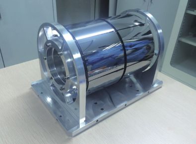
S. N. Zhang, et al. Sci. China-Phys. Mech. Astron.             February (2019)      Vol. 62    No. 2                                             029502-3

    Citation:    S. N. Zhang, A. Santangelo, M. Feroci, Y. P. Xu, F. J. Lu, Y. Chen, H. Feng, S. Zhang, S. Brandt, M. Hernanz, L. Baldini, E. Bozzo, R. Campana,
                 A. De Rosa, Y. W. Dong, Y. Evangelista, V. Karas, N. Meidinger, A. Meuris, K. Nandra, T. Pan, G. Pareschi, P. Orleanski, Q. S. Huang, S. Schanne,
                 G. Sironi, D. Spiga, J. Svoboda, G. Tagliaferri, C. Tenzer, A. Vacchi, S. Zane, D. Walton, Z. S. Wang, B. Winter, X. Wu, J. J. M. in ’t Zand, M.
                 Ahangarianabhari, G. Ambrosi, F. Ambrosino, M. Barbera, S. Basso, J. Bayer, R. Bellazzini, P. Bellutti, B. Bertucci, G. Bertuccio, G. Borghi, X.
                 L. Cao, F. Cadoux, R. Campana, F. Ceraudo, T. X. Chen, Y. P. Chen, J. Chevenez, M. Civitani, W. Cui, W. W. Cui, T. Dauser, E. Del Monte, S. Di
                 Cosimo, S. Diebold, V. Doroshenko, M. Dovciak, Y. Y. Du, L. Ducci, Q. M. Fan, Y. Favre, F. Fuschino, J. L. Gálvez, M. Gao, M. Y. Ge, O. Gevin,
                 M. Grassi, Q. Y. Gu, Y. D. Gu, D. W. Han, B. Hong, W. Hu, L. Ji, S. M. Jia, W. C. Jiang, T. Kennedy, I. Kreykenbohm, I. Kuvvetli, C. Labanti, L.
                 Latronico, G. Li, M. S. Li, X. Li, W. Li, Z. W. Li, O. Limousin, H. W. Liu, X. J. Liu, B. Lu, T. Luo, D. Macera, P. Malcovati, A. Martindale, M.
                 Michalska, B. Meng, M. Minuti, A. Morbidini, F. Muleri, S. Paltani, E. Perinati, A. Picciotto, C. Piemonte, J. L. Qu, A. Rachevski, I. Rashevskaya,
                 J. Rodriguez, T. Schanz, Z. X. Shen, L. Z. Sheng, J. B. Song, L. M. Song, C. Sgro, L. Sun, Y. Tan, P. Uttley, B. Wang, D. L. Wang, G. F. Wang, J.
                 Wang, L. P. Wang, Y. S. Wang, A. L. Watts, X. Y. Wen, J. Wilms, S. L. Xiong, J. W. Yang, S. Yang, Y. J. Yang, N. Yu, W. D. Zhang, G. Zampa, N.
                 Zampa, A. A. Zdziarski, A. M. Zhang, C. M. Zhang, F. Zhang, L. Zhang, T. Zhang, Y. Zhang, X. L. Zhang, Z. L. Zhang, B. S. Zhao, S. J. Zheng, Y.
                 P. Zhou, N. Zorzi, and J. F. Zwart, The enhanced X-ray Timing and Polarimetry mission—eXTP, Sci. China-Phys. Mech. Astron. 62, 029502 (2019),
                 https://doi.org/10.1007/s11433-018-9309-2

Contents

1 Introduction                                                                                                                                                                  029502-4

2 The scientific payload                                                                                                                                                        029502-4
   2.1 Spectroscopic focusing array (SFA) . . . . . . . . . . . . . . . . . . . . . . . . . . . . . . . . . . . . . . . . . . . . . . . . . . . . . . . . . . 029502-4
            2.1.1      Optics . . . . . . . . . . . . . . . . . . . . . . . . . . . . . . . . . . . . . . . . . . . . . . . . . . . . . . . . . . . . . . . . . . . . . . . . . . . . . 029502-5
            2.1.2      SFA detectors and electronics . . . . . . . . . . . . . . . . . . . . . . . . . . . . . . . . . . . . . . . . . . . . . . . . . . . . . . . . 029502-7
            2.1.3      The filter wheel and cooling . . . . . . . . . . . . . . . . . . . . . . . . . . . . . . . . . . . . . . . . . . . . . . . . . . . . . . . . . 029502-7
            2.1.4      Performance: Effective area and background . . . . . . . . . . . . . . . . . . . . . . . . . . . . . . . . . . . . . . . . . . 029502-8
   2.2 Large area detector (LAD) . . . . . . . . . . . . . . . . . . . . . . . . . . . . . . . . . . . . . . . . . . . . . . . . . . . . . . . . . . . . . . . . . . 029502-8
            2.2.1      The LAD architecture . . . . . . . . . . . . . . . . . . . . . . . . . . . . . . . . . . . . . . . . . . . . . . . . . . . . . . . . . . . . . . . 029502-8
            2.2.2      Detectors and electronics . . . . . . . . . . . . . . . . . . . . . . . . . . . . . . . . . . . . . . . . . . . . . . . . . . . . . . . . . . . . 029502-9
            2.2.3      Collimators, filters . . . . . . . . . . . . . . . . . . . . . . . . . . . . . . . . . . . . . . . . . . . . . . . . . . . . . . . . . . . . . . . . . 029502-11
            2.2.4      Performance: Area and background . . . . . . . . . . . . . . . . . . . . . . . . . . . . . . . . . . . . . . . . . . . . . . . . . 029502-11
   2.3 Polarimetry focusing array (PFA) . . . . . . . . . . . . . . . . . . . . . . . . . . . . . . . . . . . . . . . . . . . . . . . . . . . . . . . . . . 029502-12
            2.3.1      Detectors and electronics. . . . . . . . . . . . . . . . . . . . . . . . . . . . . . . . . . . . . . . . . . . . . . . . . . . . . . . . . . . 029502-12
            2.3.2      Performance: Area, background, MDP . . . . . . . . . . . . . . . . . . . . . . . . . . . . . . . . . . . . . . . . . . . . . . 029502-13
   2.4 Wide field monitor (WFM) . . . . . . . . . . . . . . . . . . . . . . . . . . . . . . . . . . . . . . . . . . . . . . . . . . . . . . . . . . . . . . . . 029502-15
            2.4.1      The WFM architecture . . . . . . . . . . . . . . . . . . . . . . . . . . . . . . . . . . . . . . . . . . . . . . . . . . . . . . . . . . . . . 029502-16
            2.4.2      Performance . . . . . . . . . . . . . . . . . . . . . . . . . . . . . . . . . . . . . . . . . . . . . . . . . . . . . . . . . . . . . . . . . . . . . . 029502-17

3 The mission profile                                                                                                                                                         029502-18
   3.1 The spacecraft . . . . . . . . . . . . . . . . . . . . . . . . . . . . . . . . . . . . . . . . . . . . . . . . . . . . . . . . . . . . . . . . . . . . . . . . . . . . 029502-18
   3.2 Launch and orbit . . . . . . . . . . . . . . . . . . . . . . . . . . . . . . . . . . . . . . . . . . . . . . . . . . . . . . . . . . . . . . . . . . . . . . . . . 029502-19
   3.3 The ground segment . . . . . . . . . . . . . . . . . . . . . . . . . . . . . . . . . . . . . . . . . . . . . . . . . . . . . . . . . . . . . . . . . . . . . . 029502-20

4 Observing strategy                                                                                                                                                          029502-21

5 Conclusions                                                                                                                                                                 029502-21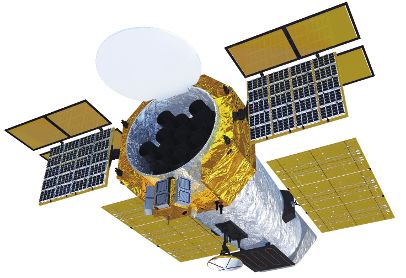
S. N. Zhang, et al. Sci. China-Phys. Mech. Astron.   February (2019)   Vol. 62   No. 2                              029502-4

1 Introduction                                                                    an extended phase A study that is expected to be completed
                                                                                  by the end of 2018 in view of a launch around 2025.
The enhanced X-ray Timing and Polarimetry mission—eXTP                               In this paper we present the technological and technical as-
is a scientific space mission designed to study the state of                      pects, and the expected performance of the instruments of the
matter under extreme conditions of density, gravity and mag-                      scientific payload, as well as the main elements and functions
netism [1]. Primary goals are the determination of the equa-                      of the mission.
tion of state of matter at supra-nuclear density, the measure-
ment of QED effects in the radiation emerging from highly
magnetized stars, and the study of matter dynamics in the                         2 The scientific payload
strong-field regime of gravity. The matter inside neutron
stars (NSs), the space-time close to black holes (BHs), and                       An artistic view of the current design of the eXTP satellite
the extremely magnetized vacuum close to magnetars are                            is shown in Figure 1. The scientific payload of the mission
among the uncharted territories of fundamental physics. The                       consists of four main instruments: the spectroscopic focusing
eXTP mission will revolutionize these areas of fundamen-                          array (SFA, sect. 2.1), the large area detector (LAD, sect. 2.2),
tal research by high precision X-ray measurements of NSs                          the polarimetry focusing array (PFA, sect. 2.3), and the wide
across the magnetic field scale and BHs across the mass scale.                    field monitor (WFM, sect. 2.4).
In addition to investigating fundamental physics, eXTP will
be a very powerful observatory for astrophysics, which will                       2.1 Spectroscopic focusing array (SFA)
provide observations of unprecedented quality on a variety of
galactic and extragalactic objects. In particular, its wide field                 The SFA consists of an array of 9 identical Wolter-I grazing-
monitoring capabilities will be highly instrumental in identi-                    incidence X-ray telescopes, and is mainly used for spectral
fying the electro-magnetic counterparts of gravitational wave                     and timing observations in the energy range 0.5-10 keV. Each
sources.                                                                          telescope consists of the thermal shield, the mirror module,
   The eXTP science case is described in four papers address-                     the electron deflector, the filter wheel, and the focal plane
ing the three main science objectives of the mission and the                      camera. A schematic view of one of the SFA telescopes is
observatory science [2-5]. They are included in this special                      shown in Figure 2. The SFA total effective area is expected
issue.                                                                            to be larger than ∼ 7400 cm2 at 2 keV, and the field of view
                                                                                  (FoV) is 12 arcmin in diameter. The SFA uses silicon drift
   The eXTP mission is an enhanced version of the Chi-
                                                                                  detectors (SDDs) as focal plane detectors. Each telescope in-
nese X-ray Timing and Polarimetry mission [6], which in
                                                                                  cludes a 19-cell SDD array, whose energy resolution is less
2011 was selected and funded for a Phase 0/A study as one
                                                                                  than 180 eV at 6 keV. The time resolution is 10 µs, and the
of the background concept missions in the Strategic Prior-
                                                                                  dead time is expected to be less than 5% at 1 Crab. The angu-
ity Space Science Program of the Chinese Academy of Sci-
                                                                                  lar resolution is required to be less than 1 arcmin (HEW). To
ences (CAS). Also in 2011, the Large Observatory for Tim-
                                                                                  meet the requirements, the working temperature of the mir-
ing (LOFT) mission concept [7, 8] was selected for an as-
                                                                                  ror modules has to be stable at (20±2) ◦ C. A thermal shield
sessment study in the context of the ESA’s Announcement of
                                                                                  is introduced to keep the temperature as steady as possible.
Opportunity for the third of the medium size missions (M3)
                                                                                  An electron deflector is installed at the bottom of the mirror
foreseen in the framework of the Agency’s Cosmic Vision
programme. The LOFT study was carried out in 2011-2014
by a consortium of European institutes. Eventually the exo-
planetary mission PLATO, considered more well-timed, was                                                                                WFM
                                                                                                                                        WFM
selected as ESA’s Cosmic Vision M3 mission. Following
this, in 2015, the European LOFT consortium and the Chi-
nese team merged the LOFT and XTP mission concepts, thus
                                                                                         LAD
                                                                                         LAD
starting the eXTP project.
   The eXTP international consortium is led by the Institute                                                                               SFA
of High Energy Physics (IHEP) of CAS, and includes other
major institutions of CAS, several Chinese Universities, and                                                          PFA
                                                                                                                       PFA
institutions from ten European countries. Other international
partners participate in eXTP as well. Overall more than 200                       Figure 1 Artistic view of the eXTP satellite. The science payload consists
scientists in over 100 institutions from about 20 countries are                   of four instruments: the focused SFA and PFA telescopes arrays, the large
members of the consortium. The mission has recently started                       area instrument LAD, and the WFM to monitor a large fraction of the sky.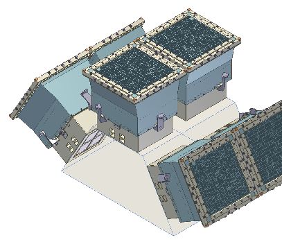
S. N. Zhang, et al. Sci. China-Phys. Mech. Astron.   February (2019)   Vol. 62   No. 2                              029502-5

                                                                                      (parabola+hyperbola) will be fabricated. The mandrel is
                                                                                      made of Aluminum and electrochemically coated with a thin
                                                                                      layer (0.100 mm) of Kanigen, a material particularly suit-
                                                                                      able to endure superpolishing by lapping. A layer of Gold
                                                                                      is deposited on the superpolished mandrel surface and the
                                                                                      successive deposition is performed by electroforming of the
                                                                                      Nickel external substrate. The mirror is then separated from
                                                                                      the mandrel by cooling it, exploiting the large difference of
                                                                                      the thermal expansion coefficients between the Aluminum of
                                                                                      the mandrels and the Nickel of the shells. An overcoating
                                                                                      of Carbon is deposited onto the Gold surface to increase the
Figure 2 The schematic structure of one of the SFA telescopes.
                                                                                      X-ray reflectivity at energies ≤ 5 keV [16].
                                                                                         A set of 39 mandrels at 60 cm length, parabola + hyper-
                                                                                      bola (30 cm×30 cm) monolithic pseudo-cylindrical mandrels
module to reduce the particle background.
                                                                                      will be developed for the four shells of PFA and all SFA mod-
                                                                                      ules. The diameters of the shells range from 507 to 267 mm.
2.1.1 Optics
                                                                                      To meet the different requirements for the angular resolution,
Since they are based on very similar concepts in this section                         and to optimize the mass constrains, two different thickness-
we discuss the optics of both the SFA and PFA. Thirteen X-                            to-diameter ratio sequences for the Nickel mirror walls of the
ray grazing-incidence Wolter-I (parabola + hyperbola) optics                          shells are considered [17, 18].
modules will be implemented onboard eXTP. The SFA in-                                    For the PFA optics, the thickness-to-radius is expected
cludes nine optics modules while four optics modules are                              to be 0.00175, with a minimum and maximum thickness of
designed for the PFA. The expected collecting area of each                            0.231 and 0.438 mm respectively. The weight of each mod-
telescope is Aoptics ' 900 cm2 at 2 keV, and Aoptics ' 550 cm2                        ule is about 82 kg (for the 39 shells) + 24 kg (for the struc-
at 6 keV. The FoV is 12 arcmin (in diameter). These figures                           ture), so that the total mass of the 4 modules is approximately
already meet the requirement of ∼ 820 cm2 at 2 keV1) . The                            416 kg. For the SFA optics, the thickness-to-radius is about
requirement for the angular resolution of the PFA optics is                           0.0009, with a minimum and maximum thickness of 0.120
< 30 arcsec (HEW, goal is 15 arcsec), more demanding than                             and 0.225 mm respectively. The weight of each module is
the 1 arcmin (HEW) angular resolution required for the SFA                            about 43 kg for the 39 shells and 13 kg for the structure, for
optics. For both types of telescopes the focal length refer-                          a total of 504 kg for 9 modules.
ence value is 525 cm. The maximum diameter of the mirror                                 The expected collecting area for a single X-ray optics mod-
shells, allowed by the envelope for a single mirror of less                           ule (both polarimetric and spectroscopic) is presented in Fig-
than 600 mm in diameter, is about 510 mm. The weight of                               ure 3, while in Figure 4 the vignetting function, inferred
the optics module is expected to be ∼50 kg for the SFA and
∼100 kg for the PFA. In Table 1 we list the main parameters                           Table 1   The main parameters of the SFA and PFA baseline optics
of the SFA and PFA optics.                                                                        Parameters                     For one telescope
   Nickel electroforming approach. The baseline technique                                        Focal length                          5.25 m
implemented for both the SFA and PFA is Nickel replica-                                            Aperture                     ≤510 mm (diameter)
tion, developed in Europe by INAF in collaboration with                                           Envelope                      ≤600 mm (diameter)
the Media Lario company. Nickel replication has already                                         Collecting area                  ≥900 cm2 @2 keV
been successfully used for high throughput X-ray telescopes                                  Collective area req.                ∼ 820 cm2 @2 keV
with good angular resolution, such as BeppoSAX [9], XMM-                                                                         ≥550 cm2 @6 keV
Newton [10] and Swift [11]. It is also the technology                                           Energy range                         0.5-10 keV
adopted for the eROSITA [12] and ART-X telescopes on-                                           Field of view                       ≥12 arcmin
board the spectrum X-GAMMA mission [13], and the IXPE                                     Angular resolution SFA                  1 arcmin (HPD)
[14] polarimetric mission. The Nickel approach is also the                                Angular resolution PFA           30 arcsec (goal 15 arcsec, HPD)
baseline for the realization of the mirrors of the FXT tele-                                Working temperature                      (20±2) ◦ C

scope aboard the Einstein Probe Chinese mission [15]. For                                 Weight per module SFA                       ∼ 50 kg
                                                                                          Weight per module PFA                       ∼ 100 kg
each mirror shell a mandrel with mirror negative profile

   1) All requirements are being consolidated in the context of the extended phase A study.
S. N. Zhang, et al. Sci. China-Phys. Mech. Astron. February (2019) Vol. 62 No. 2 029502-6
tive thin films. The mirror length is 100 mm. To achieve
the required collecting area around 200 shells need to be as-
sembled with diameters from 110 to 500 mm. The number
of shells can be significantly reduced by developing longer
On-axis collecting area (cm2)
glass mirrors. An important advantage of the SGO technique
is the light weight of the mirrors since their density is only
∼2.5 g/cm3 . Thermally slumped glass optics have been
used for the NuSTAR mission, whose telescopes contain 133
shells of thin glasses [21, 22]. During the slumping process,
the glass is slumped very slowly onto the convex surface of
the mandrel to assume its shape [23]. The temperature curve
needs to be optimized to control the slumping process and
the figure of the glass. Two furnaces temperature control of
Energy (keV) less than ±1◦ C and excellent uniformity have been used for
the preliminary study and production of cylindrical glass sub-
Figure 3 On-axis collecting area expected for the eXTP X-ray baseline
strates. Schott D263, 200-300 µm thick, is the material used
optics based on Nickel electroforming (single modules). The curve is repre-
sentative for both the stiff (PFA) and soft (SFA) configurations. The current as slumping glass. To fabricate glass mirrors with high accu-
requirements at 2 and 6 keV are shown. While the requirements are cur- racy, even higher accuracy metrology tools are required. Both
rently being consolidated, we observe that the expected performance already the mandrel and the glass are measured by a laser scanning
largely meet the requirements.
system and an interferometer.
In the context of the XTP study, cylindrical glasses with
50-60 arcsec resolution (HPD) have been produced. The
best mirror produced has an angular resolution of 36 arcsec
(HPD).
To increase the reflectivity in the range 0.5-10 keV the
Collecting area (1 module, cm2)
slumped glass substrates are coated with Platinum and Car-
bon layers. The thicknesses of the layers are optimized for
each shell to maximize the collecting area. Measurements
performed with the AFM and optical profiler have resulted in
a surface roughness of 0.32-0.37 nm. The X-ray reflectance
has been measured to be of 90% (70%) at 1 (8) keV. The
SFA module is built from individual glass segments. To
achieve large collecting surfaces, concentric shells of glasses
are stacked on top of each other starting from the central man-
drel. In this process, the cylindrical glass segments are forced
to a conical form while the middle frequency figure and mi-
Off-axis angle (arcmin) croroughness of the glass are maintained. The advantage of
Figure 4 Vignetting function at different X-ray energies or the eXTP X-ray
this process is that each glass shell is machined with respect
baseline optics based on Nickel electroforming. The case of 39 stiff shells is to the optical axis and not the last shell so there is no sig-
presented. nificant stack-up error due to assembly. The assembly sys-
tem integrates both single point diamond tools and abrasive
using well-tested simulation software tools [19,20], is shown. (grinding) wheels, which allows to reach sub-micron accu-
Preliminary analyses have been performed on the thermo- racy. Each segmented mirror is bonded to the structure using
structural behaviour. Very promising results in terms of resis- graphite spacers and epoxy with a fine optimized air pressed
tance to static stress and natural frequencies excitations have instrument. Metrology plays an essential role during the as-
been obtained using solutions based on single or double spi- sembly. We have developed three techniques to measure the
ders. geometry parameters of the module, including contact me-
Slumping Glass Optics. Slumping glass optics (SGO) is chanical probe and non-contact optical probe. The differ-
the second technology considered for the eXTP optics. The ent probes combined with the machine’s ultra-precision stage
design is based on the Wolter-I concept. Each mirror is fabri- calibrate each other to ensure an optimal measurement ac-
cated by a thermal slumping process and coated with reflec- curacy. Based on the metrology results of the free-standing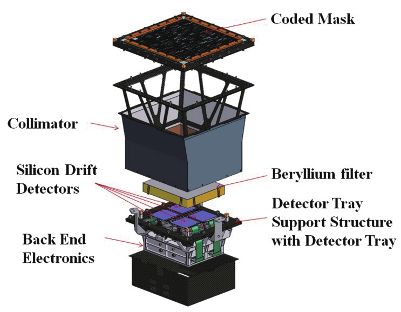
S. N. Zhang, et al. Sci. China-Phys. Mech. Astron.   February (2019)   Vol. 62   No. 2                          029502-7

mirrors and after assembly, the impact of assembly error on
the angular resolution is controlled within 1 arcmin. Proto-
types of the SFA optics have been developed by the Tongji
University, China. The 1st complete shell prototype has a fo-
cal length of 4 m and 5 shells, with the outer shell diameter of
170 mm as shown in Figure 5. Sixty shells coated with a Plat-
inum have been assembled. The prototype has been tested at
the National Astronomical Observatory of China. The HPD
of the spot has been estimated to be 3 arcmin at 2-8 keV. The
angular resolution of a complete shell prototype is estimated
                                                                                    Figure 6 SDD array for the SFA detectors. Each of the 19 hexagon cells
to be ∼1.5 arcmin.
                                                                                    has a side length of 3.2 mm and a sensitive thickness of 450 µm.

2.1.2 SFA detectors and electronics                                                 detecting area of 26.6 mm2 , and the whole detecting area of
                                                                                    the SDD array is 5 cm2 . The depletion layer is 450 µm. A
The SFA detector. The scientific objectives of the SFA require                      metal mask is planned to be implemented above the detec-
a detector with high count rate capability and time resolution,                     tor, to cover the gaps, thus decreasing the ratio of split events
along with excellent spectroscopic performance. The energy                          generated at the edge. A passive shield is used to reduce the
resolution is required to be better than 180 eV (FWHM at                            background. This consists of a deflector assembled under the
6 keV) until the end of the mission after 8 years lifetime, and                     mirror module, a baffle installed above the filter wheel, and
time resolution shall be less than 10 µs. The baseline detec-                       multi-layer composites glued around the detector with the ex-
tor consits of an array of SDDs organized in 19 hexagonal                           clusion of the entrance window.
cells. This configuration meets the aforementioned require-                            Front end electronics. The signal processing chain of each
ments (see Figure 6). Compared with CCDs, SDDs allow                                SDD cell includes a charge sensitive pre-amplifier, a fast
a much faster readout. The detector geometry ensures that                           shaper, and a slow shaper with sample and hold circuit. Since
the vast majority of source photons are focused onto the in-                        most of the incident photons will be focused onto the central
ner 7 cells of the array, whereas the cells of the outermost                        cell of the SDD array, a dedicated analogue to digital con-
ring are used to accurately determine the background. The                           version (ADC) circuit is implemented to reduce dead time
side length of a hexagon cell has thus been determined to be                        effects. For the remaining 18 cells, to simplify the readout,
3.2 mm matching the expected angular resolution of the op-                          a multiplexed solution is considered, i.e., every 6 cells share
tics. The detector has a 450 µm sensitive thickness, which                          one ADC circuit. The fast shaping time constant is ∼ 0.2 µs
delivers excellent quantum efficiency over the SFA energy                             time to allow an accurate event time determination and pile-
range. Blocking of optical photons is achieved by coating the                       up rejection. A slow shaper with a time constant of several
silicon sensor entrance window with a thin Aluminum layer                           µs allows precise signal charge measurement and therefore
of ∼80 nm thick. The SDD sensors will be provided by the                            a better spectral resolution. The concept hass been demon-
Max-Planck-Institut für Extraterrestrische Physik, Garching                        strated with discrete components already, and a more com-
(Germany) in collaboration with the Semiconductor Labora-                           pact solution based on dedicated ASICs is currently being
tory of the Max Planck Society. The fabrication of proto-                           developed.
type SDD arrays is currently ongoing. Each SDD pixel has a                             Back end electronics. An FPGA-based back-end electron-
                                                                                    ics (BEE) module is implemented to control the front-end
                                                                                    electronics (FEE), and readout the digitized data from the
                                                                                    ADCs. For each incident X-ray photon, the signal amplitude
                                                                                    and arrival time are recorded and sent to the spacecraft data
                                                                                    handling subsystem for temporary storage and telemetry. The
                                                                                    FPGA also generate housekeeping data packages that include
                                                                                    key parameters, e.g., counting rate of each cell, live time of
                                                                                    the readout circuit, and working temperatures.

                                                                                    2.1.3 The filter wheel and cooling

Figure 5   The first prototype of the telescope based on slumping glass             A filter wheel is located above the detector (see Figure 7). In
optics.                                                                             the current configuration, 4 positions corresponding to 4 op-
S. N. Zhang, et al. Sci. China-Phys. Mech. Astron.   February (2019)                                Vol. 62   No. 2                      029502-8

erational modes are foreseen: (1) Open filter, used in ground
                                                                                                                                    0.10
tests and weak sources observations. (2) Calibration. An Fe-

                                                                                                   Normalized counts (s−1 keV−1)
55 radioactive source is used for in orbit calibration. (3) Op-                                                                     0.05
tical blocking filter. This filter, consisting of a 400 nm poly-
imide and a 200 nm Aluminum film, is used to block visible                                                                          0.02
and UV light. It also prevents contamination of the detec-
tor. (4) Closed filter. A metal shutter is used to measure the                                                                      0.01

internal background, and prevents the detector from damage
during launch and extreme solar events. To compensate for                                                                          5×10⁻³

particle damage of the SDDs, especially due to protons, a low
temperature from −100◦ C to −80◦ C is needed during the op-                                                                            0.2             0.5     1        2     5   10
                                                                                                                                                                Energy (eV)
eration of the detectors. Temperature stability of ±0.5◦ C is
also required. An active method is designed to achieve the                                    Figure 9                               Expected background of the SFA.
low temperature: it includes a Helium pulse tube and loop
heat pipes.                                                                                   photon-by-photon observations of X-ray sources in the en-
                                                                                              ergy range of 2-30 keV (up to 80 keV in the expanded mode,
2.1.4 Performance: Effective area and background                                               for out-of-field-of-view burst events). The arrival time and
The total effective area of the SFA, taking into account the                                   energy of each photon are measured with high resolution and
detector efficiency and filters, is shown in Figure 8. Simi-                                    for a very large statistics of events. This enables unprece-
larly, Figure 9 shows the background expected on the basis                                    dented spectral-timing studies in the X-rays. The FoV is
of current simulations.                                                                       limited to ∼1◦ by a mechanical collimator to reduce source
                                                                                              confusion and the X-ray background. The key innovation of
2.2 Large area detector (LAD)                                                                 the LAD (as well as of the WFM, see sect. 2.4) relies on the
                                                                                              technology of large-area SDDs and capillary plate collima-
The LAD is designed to perform, on a large collecting area,                                   tors. These elements allow the construction of highly effi-
                                                                                              cient X-ray detectors, which are only a few mm thick and a
                                                                                              few hundred grams in weight, thus reducing requirements for
                                                                                              weight, volume and power by about an order of magnitude
                                                                                              with respect to proportional counters and mechanical colli-
                                                                                              mators used in the past generation of large area instruments
                                                                                              [24]. The LAD main specifications are listed in Table 2.

                                                                                              2.2.1 The LAD architecture

                                                                                              The LAD large area is achieved by a modular and intrinsi-
Figure 7 The schematics of the filter wheel.                                                  cally highly redundant design. The fundamental units of the
                                                                                              instrument are the LAD modules. Each module consists of
                                                                                              a set of 4×4 large area SDDs and 4×4 capillary plate colli-
                            8000                                                              mators, supported by two grid-like frames. Each of the SDDs
                                                                                              are equipped with the FEE, and interfaced to a support frame,
                                                                                              the detector tray. The detector tray hosts the module back-end
     Effective Area (cm2)

                            6000
                                                                                              electronics (MBEE) on its back-side, which includes the dig-
                                                                                              ital electronics and power supply units (PSUs). The detector
                            4000
                                                                                              tray and the collimator tray are bolted together to form the
                                                                                              complete LAD module. The module and its main compo-
                            2000
                                                                                              nents are shown in Figure 10. Modules are embodied in two
                                                                                              panels, Carbon-fiber frames deployed from the optical bench.
                               0                                                              Each of the panels hosts 20 (5 × 4) modules, for a total of 40
                                   0.5   1        2            5        10
                                          Energy (eV)                                         modules or 640 detectors. Part of the panel is the panel back-
Figure 8 The effective area of the SFA. The efficiency of the detectors and                      end electronics (PBEE), that interfaces the 20 modules to the
the filters is taken into account.                                                            central instrument control unit (ICU).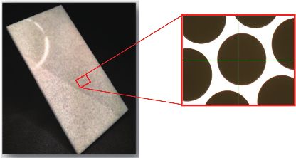
S. N. Zhang, et al. Sci. China-Phys. Mech. Astron.   February (2019)   Vol. 62   No. 2                    029502-9

                                                                                         The LAD panel structure in Carbon fiber reinforced plastic
Table 2 LAD main specifications.
                                                                                      (CFRP) supports the LAD modules and the PBEE. The key
                Parameter                               Value
                                                                                      requirements for this structure are to withstand the launch,
       Energy range (nominal)             2-30 keV (extended 30-80 keV)
                                                                                      provide mechanical and thermo-elastic stability to the mod-
               Effective area                       3.4 m2 at 8 keV
                                                                                      ules (e.g., alignment), and aid the thermal control. To this
                                                 0.37 m2 at 30 keV
                                                                                      purpose a common radiator is used on the back side of the
 Energy resolution (FWHM, at 6 keV)             < 260 eV (all events)
                                             < 200 eV (40% of events)
                                                                                      panel. The interfaces to the module, optical bench and mech-
               Field of view                         < 60 arcmin
                                                                                      anisms are in Titanium. A Sun shield protects the LAD pan-
              Time resolution                           10 µs                         els from direct solar irradiation. Twenty modules are con-
         Dead time (at 1 Crab)                 < 0.5%, (goal < 0.1%)                  trolled by two PBEEs, located underneath the panel near the
                Background                           < 10 mCrab                       hinge to minimise the amount of harness that has to cross
  Maximum source flux (continuous)                  > 300 mCrab                       the hingeline. The PBEE sends commands to the MBEEs
    Maximum source flux (for 8 h)                     > 15 Crab                       and distributes clocks and power. It receives data from the
                Total mass                            ∼ 360 kg                        MBEEs and sends them to the ICU (see sect. 2.2.2). The
                  Power                                ∼ 400 W                        ICU is cold redundant. In total, the LAD is composed of 640
                                                                                      SDDs, 640 CPs and 5120 ASICs (8 per SDD). To monitor
                                                                                      the internal background, one out of 40 modules is equipped
                                                                                      with a “blocked collimator” made of the same materials of
                                                                                      the other collimators but with no pores.
  Collimators
                                                                Frame

 Collimator                                                                           2.2.2 Detectors and electronics
  clamps
                                                                                      The SDDs. Large-area SDDs [25] were developed for the
SDDs+ FEEs
                                                                                      inner tracking system of the ALICE experiment at the large
                                                                                      hadron collider [26]. They were later optimized for the use
                                                                                      as photon detectors onboard LOFT [27] with typical size of
   Radiator                                                                           11 cm×7 cm and 450 µm thickness. SDDs are capable to
                                                                                      read-out large photon collecting areas with a small set of low-
                                                                                      capacitance (and thus low-noise) anodes, and are light with
                                                                                      ∼1 kg/m2 . The working principle is shown in Figure 11. The
Figure 10     LAD module exploded.
                                                                                      cloud of electrons produced by the interaction of the incident
                                                                                      photon drifts towards the read-out anodes at ∼0 V, driven by
    To summarize, the LAD module consists of:                                         a constant electric field generated by a progressively decreas-
    • A collimator tray, containing 16 co-aligned collimator                          ing negative voltage applied to the cathodes. Diffusion causes
plate tiles (one per SDD, see sect. 2.2.3).                                           the electron cloud to expand by a factor depending on the
    • The detector tray, containing 16 SDDs and the FEEs. It                          square root of the drift time. The charge distribution over the
interfaces the MBEE through a built-in rigid-flex harness and                         collecting anodes thus depends on the absorption point in the
hyperstac connectors.                                                                 detector.
    • The MBEE, organized in two sections, each interfacing                              While drifting and diffusing, the electron cloud size in-
8 detectors. It is located on the back side of the detector tray.                     creases and, at a distance d from the photon absorption point,
It controls the SDDs, FEEs and PSUs, reads out the FEE dig-                           the typical
                                                                                            √      size of the Gaussian-shaped cloud is given by
itized events, generates housekeeping data and ratemeters,                            σ ≃       qE × d, where kb is the Boltzmann constant, T is
                                                                                               2kb T

formats and time-stamps each event, and transmits it to the                           the temperature, q is the electron charge, and E is the drift
PBEE.                                                                                 electric field. The cloud arriving at the anodes can be de-
    • A PSU located within the same structure of the MBEE.                            scribed by a Gaussian function, with an area A equal to the
It converts the supply power to low (3 V), medium (100 V)                             total charge (i.e., the photon energy), a mean value m rep-
and high (1.3 kV) voltages for the SDDs, FEEs and ASICs.                              resenting the “anodic” coordinate of the impact point, and a
    • A 300 µm Lead back-shield, to reduce the background                             width σ that depends on the absorption point.
events in the SDDs, and a 2 mm Aluminum radiator to dis-                                 Each LAD detector is segmented in two halves, with 2 se-
sipate heat from the module to the backside of the module                             ries of 112 read-out anodes (with 970 µm pitch) at the two
box.                                                                                  edges and the highest voltage along its symmetry axis. A drift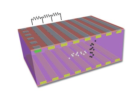
S. N. Zhang, et al. Sci. China-Phys. Mech. Astron.   February (2019)   Vol. 62   No. 2                         029502-10

field of 370 V/cm (1300 V maximum voltage) gives a drift
velocity of ∼5 mm/µs and a maximum drift time of ∼7 µs.
This is the largest contribution to the uncertainty in the mea-
surement of the arrival time of the photon. The segmentation
into 640 detectors and 144 × 103 electronics channels insures
that the rate on the individual channel is very low even for
very bright sources. Pile-up or dead-time effects are therefore
negligible. On an equatorial orbit, to maintain the required
energy resolution until the end of life, the detectors need to
be moderately cooled (−10◦ C) to reduce the leakage current.                        Figure 12 A schematic of the LAD Front End Electronics.

Considering the large size of the LAD this is achieved with
passive cooling.
   The ASICS. For the high-density read-out of the detector
dedicated ASICs with excellent performance and low power
(requirement is 17 e− rms noise with 650 µW per channel)
are needed. The read-out is performed by full-custom 8×32-
channel IDeF-X ASICs, inherited from the IDeF-X HD and
IDeF-X BD ASICs successfully used in the ESA’s solar or-
biter mission [28,29] with A/D conversion carried out by one
16-channel OWB-1 ASIC for every detector [30]. The dy-
namic range of the read-out electronics is required to record
events with energy up more than 80 keV. Events in the nom-
inal energy range (2-30 keV) are transmitted with 60 eV bin-
ning, while those in the extended energy range (30-8 keV)
are transmitted with reduced energy information (2 keV wide
bins) as they will be used to study the timing properties                           Figure 13 The protytpe of the LAD FEE realized for the LOFT study.

of bright/hard events shining from outside the FoV (e.g.,
gamma-ray bursts, magnetar flares).                                                    Back-end electronics. When the collected signal charge
   The read-out ASICs are integrated on a rigid-flex PCB                            exceeds a programmable threshold in one of the ASIC chan-
forming the FEE, with the task of providing filtered biases to                      nels, a trigger is generated and forwarded to the BEE. In case
SDDs and ASICs, I/O interfaces, and mechanical support and                          of a confirmed valid trigger pattern, the collected signals in
interface to the module. The SDD will be back-illuminated,                          all ASICs of the respective detector half are then digitised
allowing for direct wire-bonding of the anode pads to the                           and passed on to the BEEs. Following the A/D conversion,
ASIC input pads. The flat cable connection to the MBEE is                           the BEE event processing pipeline is activated: a time tag
part of the rigid-flex PCB structure. A view of the CAD de-                         is added to each event, and a pedestal and common noise
sign of the LAD FEE and the mechanical prototype realized                           subtraction is performed. In addition, energy reconstruction
for the ESA’s LOFT study are shown in Figures 12 and 13.                            takes place to determine the event parameters. Besides the
                                                                                    event processing, the BEE controls the FEE and PSU op-
                                                                                    eration, generates housekeeping data and rate meters, and
                                                                                    transmits formatted event packets onward. The LAD BBE
                                                                                    is organised into two hierarchical levels, due to the number
                                                                                    of detectors in the design. The MBEE will be located on
                                                                                    the back side of the detector tray and is organised in two
                                                                                    PCBs, interfacing 8 detectors each. The central component of
                                                                                    each MBEE PCB is an RTAX-SL FPGA. The PBEE located
                                                                                    on the back side of the panel interfaces each of the twenty
                                                                                    MBEEs and the ICU. The two PBEEs also make use of the
                                                                                    same FPGA and collect and buffer the received event packets,
                                                                                    reorganise the data depending on the observation mode, and
                                                                                    transfer the data to the data handling unit (DHU) of the ICU
Figure 11   SDD working principle.                                                  along with the housekeeping data via a SpaceWire interface.
S. N. Zhang, et al. Sci. China-Phys. Mech. Astron. February (2019) Vol. 62 No. 2 029502-11
Instrument control unit. The ICU forms the central con- measurements [34, 35]; (4) secondary cosmic rays, estimated
trolling element of the instrument. It provides the interface from AMS measurements [34, 35], and analytically modeled
to the spacecraft OBDH and also access to all instrument by Mizuno et al. [36]; (5) earth albedo neutrons, modelled
sub-systems via SpaceWire. The ICU box consists of three with the QinetiQ Atmospheric Radiation Model (QARM)
components: the DHU, the mass memory, the power dis- [37]; (6) natural radioactivity. Since the lead-glass collima-
tribution unit (PDU). Standard tasks performed at the ICU tors contain Potassium, radioactivity of 40 K has to be con-
level involve telecommand execution and distribution, access sidered. This component will be largely reduced by adopt-
to mass memory, time distribution and synchronisation, data ing the capillary plate technology of NNVT, which is almost
processing and compression, housekeeping data collection, potassium-free.
instrument health monitoring and calibration tasks. The ICU To estimate the LAD background we performed Monte
box contains each PCB board twice for cold redundancy. Carlo simulations by using the Geant-4 Monte Carlo toolkit
[38]. The total background is shown in Figure 15(a), to-
2.2.3 Collimators, filters gether with the spectrum of a 10 mCrab point-like source
(dashed line). The main background contribution is due to
To get full advantage of the compact detector design, a sim-
CXB photons, that leak from and are scattered in the col-
ilarly compact collimator design is provided by the mechan-
limators or in the detector itself. The diffuse emission col-
ical structure of the mature technology of the micro-channel
lected through the FoV and the particle background are a mi-
plates, the capillary plates. In the LAD geometry, it is a 5 mm
nor contribution to the total count rate. Fluorescence emis-
thick sheet of lead-glass (>40% Pb mass fraction) with the
sion from the Lead contained in the collimator glass (L-
same dimensions of the SDD detector, perforated by thou-
shell lines at 10.55 and 12.61 keV) and from the Copper
sands of round micro-pores with a 83 µm diameter, limiting
contained in the FEE PCB board (K-shell lines at 8.05 and
the FoV to 0.95◦ (FWHM). The open area ratio of the de-
vice is ≥75% (Figure 14). The thermal and optical design is 10−1
(a) Aperture CXB
then completed by an additional optical filter, composed by a CXB-induced
Albedo γ -rays
thin (1 µm thickness) Kapton foil coated on both sides with Particle(p,e ±, α)
10−2
40 nm of Aluminum. This is to guarantee a 10−6 filtering on Albedo neutrons
Counts (cm−2 s−1 keV−1)
40
K activity
IR/Visible/UV light, while transmitting >90% of the light at Total background
10−3 10 mCrab
2 keV and above.
2.2.4 Performance: Area and background 10−4
eXTP will be launched into an almost equatorial low-earth
10−5
orbit at an altitude of ∼550 km. At these latitudes, the ge-
omagnetic field effectively screens primary cosmic rays up
10−6
to energies of a few GeVs. Moreover, the satellite crosses 2 3 5 10 20 30 50 60
Energy (keV)
the South Atlantic Anomaly only in its external regions, thus
minimizing the activation of materials. The main sources of 1.2
(b) Model CXB Neutrons
Total Albedo γ Particles
background considered in the simulation studies [31] are: (1)
cosmic diffuse X-ray background [32]; (2) earth albedo γ- 1.0
rays. We assumed the albedo spectrum as measured by BAT
Ratew.r.t.mean
0.8
[33]; (3) residual primary cosmic rays, estimated from AMS
0.6
0.4
0.2
0.0
0 50 100 150 200 250 300 350
Pointing direction to Earth angle θ E (degrees)
Figure 15 (a) Estimates of the LAD background. (b) LAD background
modulation. θE = 0◦ corresponds to the Earth’s center aligned with the field
Figure 14 A prototype of the LAD Collimator developed by NNVT. of view, while θE = 180◦ corresponds to the Earth at the instrument nadir.S. N. Zhang, et al. Sci. China-Phys. Mech. Astron. February (2019) Vol. 62 No. 2 029502-12
8.90 keV) is present. The Figure 15(b) shows an evaluation of
the background as a function of the angle between the LAD
pointing direction and the center of the Earth. The maximum
expected modulation of the background is ∼10%. Since it is
due to geometry, it can be predicted and modeled. By using a
set of “blocked” detectors to monitor the instantaneous back-
ground, the overall background can be constrained to better
than 0.5%.
The effective area of the LAD, shown in Figure 16 com-
pared to that of the AstroSat-LAXPC and RXTE-PCA, the
largest area instruments flown as of today, implies a count
rate of ∼80000 cts/s for a Crab-like spectrum. In Figure 17
we show the minimum detectable flux (MDF) in the 2-10 keV
range accounting for a 0.3% systematics uncertainty on the
background subtraction. These curves show that the statis-
tical LAD 3σ sensitivity for persistent sources is exception-
ally high and amounts to ∼ 0.5 mCrab/s. Due to the enor- Figure 17 The LAD minimum detectable flux (MDF) in 2-10 keV. The
curves refer to a signal-to-noise ratio of 3, 5 and 100 respectively. We also
mous amount of collected photons, for exposures larger than included a 0.3% systematics uncertainties on the background subtraction.
104 s, the systematics in the background subtraction domi-
nate the uncertainties. The MDF curves show that a 5σ de-
tection of a 0.1 mCrab-like source takes about 200 s, while 2.3 Polarimetry focusing array (PFA)
a signal-to-noise ratio of 100 (needed e.g., to investigate
emission line profiles in X-ray spectra of accreting BHs and The PFA consists of 4 identical telescopes optimized for X-
NSs) is reached in 5000 s for a 1 mCrab source. The back- ray imaging polarimetry, sensitive in the energy range of
ground level and residual systematics requirements are driven 2-8 keV. In synergy with the SFA and LAD, the PFA offers
by the strong field gravity objectives for relatively faint (1- spatial, energy, and/or temporal resolved X-ray polarimetry at
10 mCrab) sources like most AGNs. Simulations show that, high sensitivity. PFA is also the only instrument on eXTP that
if the background variations are modelled on timescales of a has an imaging capability better than an arcminute, which
few ks to a level of 0.3% of the mean background level, it will may help to discriminate and remove source confusions oc-
be possible for example to observe a large sample of AGNs curring in other instruments. The main features of the PFA
to measure BH spins with an accuracy of 20%, and to carry optics have already been discussed in sect. 2.1. The PFA pa-
out reverberation mapping measurements on AGNs [4, 39]. rameters and specifications are listed in Table 3.
2.3.1 Detectors and electronics.
×104
3.5
eXTP−SFA
eXTP−LAD The gas pixel detector (GPD) is adopted as the focal plane
3.0 RXTE−PCA
ASTROSAT − LAXPC
polarimeter for the PFA. The GPD was invented and devel-
2.5 oped by the INFN-Pisa group, and its principles are widely
Effective Area (cm2)
described in refs. [40-43]. A schematic drawing of the
2.0
detector is shown in Figure 18 for illustration. It is a gas
1.5 chamber sealed by a 50 µm thick Beryllium entrance win-
dow. The chamber is vacuumed and baked out before filled
1.0
with the working gas (dimethyl ether or DME at 0.8 atm),
0.5 which absorbs the incident X-rays and converts them to pho-
toelectrons, whose emission angle encodes the information
0.0
100 101 102 about the X-ray polarization and is thus the key physical pa-
Energy (keV)
rameter to be measured. A drift field of about 2 kV cm−1 is
Figure 16 The eXTP LAD effective area is shown, in comparison with that applied in the chamber to drive secondary electrons ionized
of the AstroSat-LAXPC and RXTE-PCA, the largest area instruments flown
as of today. The eXTP-LAD area largely surpasses any past or currently fly- by the initial photoelectron to move toward the anode. To
ing mission and features an unprecedented value of about 3.4 m2 at 6 keV. enable measurements with a sufficient signal-to-noise ratio,
In the figure the eXTP soft focusing array effective area is also shown. a gas electron multiplier (GEM) is mounted above the anodeS. N. Zhang, et al. Sci. China-Phys. Mech. Astron. February (2019) Vol. 62 No. 2 029502-13
to multiply the number of electrons by a gain factor of a few
hundred, which can be adjusted by the high voltage across
the top and bottom layer of the GEM. Beneath the GEM is
Y (mm)
Y (mm)
positioned the key element of the GPD, the readout ASIC
chip [44, 45], which is pixelated to have a pitch of 50 µm
and responsible for the collection and measure of the charges
after multiplication. The ASIC has a dimension 1.5 cm×
1.5 cm, which defines the sensitive region of the detector. The X (mm) X (mm)
readout noise is around 50 e− for the ASIC. The energy reso-
lution is typical for a gas detector, i.e., 15%-20% at 6 keV. In
brief, with the GPD, one is able to measure the 2D ionization
track of the photoelectron in the gas chamber (see Figure 19
Y (mm)
Y (mm)
for examples), and infer the polarization of the incident X-ray
beam via the modulation of the emission angle reconstructed
from the track image. The BEE is designed to control and
operate the ASIC, drive the analog to digital conversion, or-
ganize and store the data, and communicate with the satel- X (mm) X (mm)
lite. They also regulate the high voltage modules, which are
needed for the drift field and to power the GEM field.
Y (mm)
Table 3 PFA main specifications
Parameter Value
Gas mixture pure DME (CH3-O-CH3) at 0.8 atm
Absorption depth 1 cm
Window 50 µm Be
X (mm)
Energy range 2-8 keV
Effective area 915 cm2 at 2 keV Figure 19 Example track images measured with the GPD at different en-
495 cm2 at 3 keV ergies.
216 cm2 at 4 keV
46 cm2 at 6 keV
2.3.2 Performance: Area, background, MDP
Modulation factor 38% at 3 keV
57% at 6 keV For a polarized X-ray source, the distribution of the photo-
Energy resolution (FWHM/E) < 18% at 6 keV electron emission angle (ϕ) projected on the focal plane is
Field of view 8 arcmin modulated by the cosine function (see Figure 20 for an exam-
Time resolution < 500 µs ple) N(ϕ) = A + B cos2 (ϕ − ϕ0 ), where A and B are constants
and ϕ0 is the position angle of polarization. The amplitude
of the modulation is linearly scaled with the degree of po-
larization of the incident beam. In response to a fully polar-
ized X-ray source, the amplitude of modulation is also called
the modulation factor µ = max−min
max+min = 2A+B . This is one of
B
the most important parameters that determine the sensitivity
of the polarimeter. The simulated and measured modulation
factor versus energy is shown in Figure 21. It decreases with
decreasing energy for two reasons. First, the Coulomb scat-
tering of the photoelectron by the nucleus will randomize the
emission angle and lower the modulation degree, which be-
comes more important at low energies. Second, due to the
shorter range of the track at low energies, the reconstruction
of the emission angle becomes more difficult and is limited
by the finite pixel size.
Figure 18 A schematic drawing of the GPD. The total effective area of the four telescopes, including theS. N. Zhang, et al. Sci. China-Phys. Mech. Astron. February (2019) Vol. 62 No. 2 029502-14
GPD, is shown in Figure 22 summed for the four telescopes
in PFA. The total background, taking into account the cos-
mic diffuse X-ray background and the particle induced back-
ground, is estimated to be about 6 × 10⁻³ counts s−1 in the
energy range of 2-8 keV in the source aperture. By compar-
ison, the Crab nebula will result in ∼1200 counts s−1 with
the 4 GPDs in the same energy band. As the majority of tar-
gets of eXTP will be bright sources in our Milky Way, such a
background will be negligible for observations in most cases.
The sensitivity of the polarimeter is usually defined as
the minimum √ detectable polarization (MDP), described as Figure 22 Total effective area of the four PFA telescopes in combination
MDP = 4.29
µ t , where µ is the modulation factor,
S A+B
A is the with the optics and detector.
effective area, S is the source intensity in photons cm−2 s−1 ,
B is the background rate in the source aperture in counts s−1 ,
t is the exposure time, and 4.29 corresponds to a confidence
level of 99%. In cases where the background is not important,
the MDP can be approximated as MDP = µ 4.29 √
S At
. Thus, the
sensitivity is not
√ only a function of the effective area, but cor-
related with µ A, the quality curve of a polarimeter. Given
the modulation factor and the effective area, the quality curve
of PFA is shown in Figure 23. As one can see, the effec-
tive area peaks at about 2 keV while the sensitivity peaks at
√
Figure 23 Quality curve (µ A) for the four PFA telescopes.
around 3 keV due to the increase of the modulation factor
with energy.
Another important parameter for a polarimeter is its sys-
tematic error, i.e., the residual modulation seen with fully un-
polarized sources. The systematic error will limit the sensi-
tivity of the polarimeter no matter how bright the source is
and how long the exposure is. The low systematics of the
Figure 20 Modulation curve measured with fully polarized X-rays of
GPD have been widely discussed in refs. [43, 46-48]. In gen-
6.14 keV (45◦ Bragg diffraction with a LiF crystal). The curve gives the
best-fit modulation function, with a degree of modulation 58.2% ± 0.7%. eral, the systematics can be controlled below 1% with the
GPD only. The optics is not expected to contribute to the sys-
tematics of polarization measurements due to its grazing in-
cidence angle and symmetric geometry. However, this needs
to be tested in the future. If the instrument is well calibrated,
the systematics can be determined and subtracted, leading to
rather low systematics.
A simple way to estimate the sensitivity given a source
with a spectrum similar to that of the Crab nebula is described
below. In the energy band of 2-8 keV, the mean modulation
factor is ∼0.23 weighted by the observed Crab nebula spec-
trum. In the case of negligible background, an exposure of
1 ks of the Crab nebula will result in an MDP of 1.7%. Sen-
sitivities for observations with sources of different intensities
Figure 21 Modulation factor of the GPD. The points are measurements and different exposure times can be scaled by simply using
and the curve is obtained from simulation. the equation for the MDP. We also note that the MDP quotedS. N. Zhang, et al. Sci. China-Phys. Mech. Astron. February (2019) Vol. 62 No. 2 029502-15
above indicates a detection at 99% confidence level (a chance
probability of 1% of having such a level of measurement from
guard region
a fully unpolarized source), and one needs more observing Incident photons
time to achieve a precise measurement with a significance of
72,5 mm
3σ or more [49].
35 mm
2.4 Wide field monitor (WFM)
The WFM is based on three pairs of coded mask cam-
pitch charge cloud
eras equipped with position-sensitive SDDs, covering 4.1 sr anodes
(∼33%) of the sky and operating in the energy range 2-50 keV
[50]. The effective FoV of each camera pair is ∼70◦ ×70◦ and Figure 25 Details of the working principle.
∼90◦ × 90◦ at zero response. The peak sensitivity is reached
along the LAD pointing direction. The energy resolution is Table 4 The WFM main parameters and performance
∼300 eV at 6 keV, and the absolute time accuracy is 1 µs. Parameters Anticipated value
Pairs of two orthogonal cameras are combined to obtain accu- Location accuracy < 1 arcmin
rate 2D positions of the monitored sources. The three camera < 30 arcsec for P/L
pairs (six cameras in total) are arranged in a baseline config- Angular resolution < 4.3 arcmin (FWHM)
uration of −60◦ , 0◦ , 60◦ as shown in Figure 24. The WFM req. 5 arcmin (FWHM)
Peak sensitivity in LAD direction < 0.6 Crab (1 s), req. < 1 Crab
main parameters and anticipated performance are listed in
2.1 mCrab (50 ks), req. 5 mCrab
Table 4.
Absolute flux accuracy < 20%
The WFM detector plane is based on the same large area
Field of view at 0% response 1.75π sr=5.5 sr
SDD technology developed for the LAD. The detector geom-
at 20% of peak camera response 1.33π sr =4.1 sr
etry has been sligthly modified to enable 2D imaging. When
Energy range 2-50 keV
a photon is absorbed by the SDD, it generates an electron
Energy resolution (FWHM) < 300 eV at 6 keV
cloud that is focused on the middle plane of the detector, and req. < 500 eV at 6 keV
then drifts towards the anodes at constant speed. As already Energy scale accuracy < 2%
discussed in sect. 2.2.2, while drifting, the electron cloud size Energy bands for compressed images ≥ 64
increases due to diffusion. As we already said, it can be de- Field of view Camera: ∼ 90◦ × 90◦ FWZR
scribed with a Gaussian function, with an area A equal to 3 Pairs ∼ 180◦ × 90◦ FWZR
the total charge (i.e the photon energy), a mean value m rep- Time resolution ≤ 300 s for images
resenting the “anodic” coordinate of the impact point and a < 10 µs for event data
width σ, which depends on the “drift” coordinate of the ab- Absolute time calibration < 2 µs, 1 µs for P/L
sorption point. See also Figure 25. Burst trigger scale 10 ms up to 300 s
Number of GRB triggers > 1 GRB triggers per orbit
mass 11.2 kg per camera
78.5 kg for 3 pairs (including ICU)
Nominal power 72 W (including ICU)
Detector Op. temperature < −20◦ C
Typical/max data rate 50/100 kbits/s (after compression)
For each photon, we measure the energy, proportional to
the collected charge, the so-called X-position, the center of
the charge cloud (< 60 µm), the Y-position proportional to
the width of the charge cloud (You can also read