The Intersection of HFC and 5G - NCTA Technical Papers
←
→
Page content transcription
If your browser does not render page correctly, please read the page content below
The Intersection of HFC and 5G

   A Technical Paper prepared for SCTE/ISBE by

                 Keith R. Hayes
                    Principal
          Broadband Advisors Group, LLC
     175 Hog Farm Circle Canton, GA 30115
                  770-378-3595
    Keith.hayes@broadbandadvisorsgroup.com

   © 2017 SCTE-ISBE and NCTA. All rights reserved.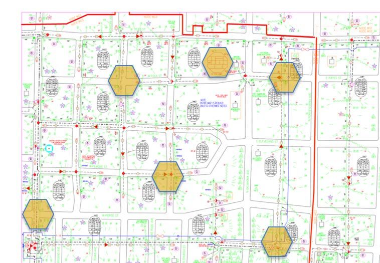
Table of Contents
Title                                                                                Page Number
Introduction ________________________________________________________________________ 3
Content ___________________________________________________________________________ 3
 1. Wireless Mobility Evolution _______________________________________________________ 3
 2. 5G Timeline and Foundational Pillars _______________________________________________ 4
 3. 5G Spectrum and Radio Access Network (RAN) Densification ____________________________ 7
 4. The 5G PAC (Power, Attachment, Connectivity) Conundrum ____________________________ 10
Conclusion ________________________________________________________________________ 12
Abbreviations ______________________________________________________________________ 13
Bibliography & References ___________________________________________________________ 14

                                        List of Figures
Title                                                                                Page Number
Figure 1 – Cellular Standards Timeline. Source: Broadband Advisors Group, LLC                      3
Figure 2 – Verizon Wireless and ATT Coverage Map.         Source: Engadget.com                     5
Figure 3 – Key Capabilities IMT 2020 (5G) vs IMT 2015.       Source: ITU-R M.2083.0                6
Figure 4 – 3GPP Release Calendar.         Source: 3GPP.org                                         7
Figure 5 – Spectrum by Carrier US.        Source: Sprint                                           9
Figure 6 – Cellular Block Licenses – top 3 US markets.      Source: FCC                             10
Figure 7 – 500-foot small cells, 1-mile diameter Macro cell. Source: Broadband Advisors Group, LLC 11
Figure 8 – 500-foot small cells integrated with HFC network. Source: Broadband Advisors Group, LLC
12

                         © 2017 SCTE-ISBE and NCTA. All rights reserved.                             2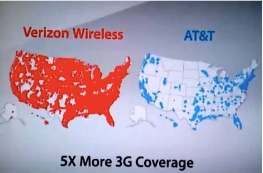
Introduction
5G. 5G. 5G. On billboards, in your inbox, at your favorite tech blog:

    •     5G - What is it?
    •     5G- Where is it?
    •     5G - WHEN is it?
    •     5G - How will it be different for users and the supporting infrastructure?
    •     5G - Why do we need it?

One of the foundational differences of 5G from the previous mobile communications Generations is its
density – perhaps 10x or more than 4G – driving the need for Location, Power, and Connectivity for the
Radios that the Hybrid Fiber-Coax (HFC) network is potentially well-equipped to support. This paper will
delve into the 5G topology to answer those questions and review performance expectations and how they
might map into an HFC network with Data Over Cable Service Interface Specifications (DOCSIS) 3.0
and DOCSIS 3.1

                                               Content
1. Wireless Mobility Evolution

        Figure 1 - Cellular Standards Timeline Source: Broadband Advisors Group, LLC

Cellular communications as we know it today began in the early 1980s with the Advanced Mobile Phone
System (AMPS), often colloquially referred to as Analog Mobile Phone Standard since the
communication was indeed analog and could be listened to (one end of the call) by an eavesdropper with
a scanner. The AMPS standard broke the spectrum bottleneck and lowered power requirements for the
mobile stations by replicating the spectrum bandwidth through “cells”, radio transmitters/receivers
serving a specified geographic area. Adjacent “cells” would use different frequencies to minimize
interference, and the key to operational success was the Mobile Switching Telecommunications Office
which through telemetry with the handset supported switching from one cell to the next rapidly enough
that calls would stay connected and conversations would be able to be conducted normally. AMPS was
launched in the 850 megahertz (MHz) spectrum, and was subsequently expanded into reclaimed ultra-
high frequency (UHF) broadcast spectrum to add bandwidth.

As mobility technology developed in the late 1980’s, there was an effort in Europe to develop mobility
standards that would be digital, work cross-platform, and more importantly enable international roaming
between countries, and the Global System for Mobile (GSM) standard set came to life. GSM is a joint

                             © 2017 SCTE-ISBE and NCTA. All rights reserved.                              3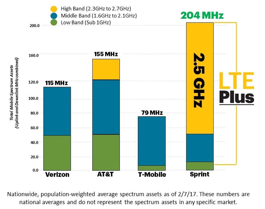
Time Division Multiple Access (TDMA) / Frequency Division Multiple Access (FDMA) modulation
schema, and also brought along the Simple Message System (SMS) with its 160-character limitation.

The first packet-switched cellular data service, General Packet Radio Service (GPRS) introduced data
service to complement voice and SMS around 2000.

As data use ballooned, GSM continued its development with the Enhanced Data Rates for Global
Evolution (EDGE) that was marketed by some operators as 3G for third-generation cellular capabilities.
Concurrently a competing standard – Code Division Multiple Access (CDMA) was developed and in the
United States some providers chose GSM (AT&T, T-Mobile) while the others chose CDMA (Verizon,
Sprint, US Cellular) setting up a handset challenge as for many years handsets only had one chipset or the
other in them and could not operate on the other network. Both standard sets supported higher data rates
through denser orders of modulation.

CDMA was further enhanced with Evolution – Data Optimized (EV-DO) which introduced a separate
data channel that would work in tandem with the voice channel. High-Speed Packet Access (HSPA) was
the corollary in the GSM ecosystem.

Recognizing that there was both an insatiable demand for mobile data consumption and that handsets
would soon be available with chipsets that could support both GSM and CDMA, the 3 Generation
Partnership Project (3GPP), a consortium of international standards bodies charted a path of network
development towards the 4th Generation environment, which they named Long Term Evolution (LTE),
trademarked by the European Telecommunications Standards Institute – (ETSI) that would provide both
platforms with download speeds of up to 300 Megabits per second (Mbps) per cell, along with support for
additional frequencies and improved centralized communications management.

Release 8 LTE provided a pre-4G capacity and bandwidth network performance enhancement including
carrier-width support from as little as 1.4 MHz to as much as 20 MHz and a much more spectrally-
efficient air interface modulation – Orthogonal Frequency Division Multiple Access (OFDMA). The
rapid improvement in data performance provided impetus for operators to market these enhancements as
4G though officially 4G was tied to release 10 that included carrier aggregation and Multiple In Multiple
Out (MIMO) antenna support. Release 10 is marketed as “True 4G” or LTE Plus in Sprints case.

2. 5G Timeline and Foundational Pillars
As the mobile environment moves towards 5G, it is important to understand that there is are marketing
and user-experience components that have driven consumer acceptance and expectations of the
performance of the cellular networks. Two main factors have been in play:

1: Coverage – how much of the US the network covered – we all remember the Verizon television
commercials with the “Can you hear me now?” guy – giving customers confidence their phone calls
would connect and wouldn’t drop.

2: Connectivity – as in to the internet – with increasing performance; 3G, LTE, 4G, LTE-Plus, along with
battling maps in TV commercials and on billboards.

                          © 2017 SCTE-ISBE and NCTA. All rights reserved.                                   4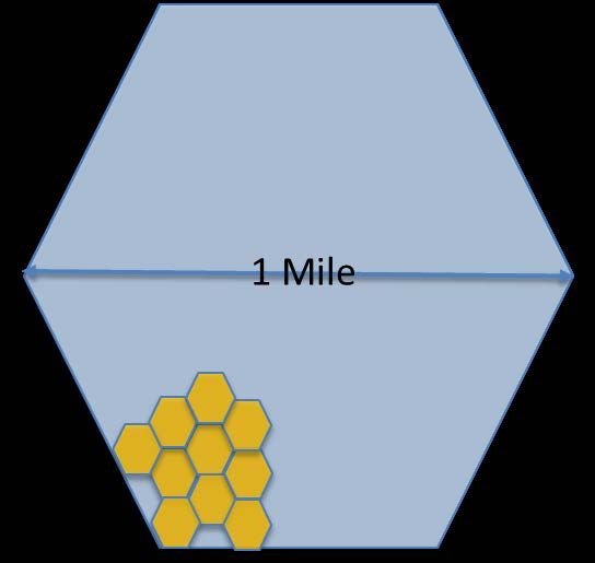
Figure 2 – Verizon Wireless and ATT Coverage Map Source: Engadget.com

What was not messaged, marketed, or even remotely hinted at was the speed/bandwidth of the data
connection, contrary to how wireline (or satellite) internet services are sold with claims of “Speeds up
to…X Mbps” with the FCC Broadband America report and sites like Speedtest.net validating those
claims. There are a couple of key differentiators that drive this dichotomy. First, 4G/LTE handsets and
networks under optimal conditions can deliver speeds for a test of up to 100 Mbps, but in reality, given
that one phone and user can only do one thing at one time, there is not a practical need for more than a
few Mbps for typically video streaming. Second, except for Wi-Fi tethers, only one device, the mobile
phone, is consuming bandwidth concurrently, unlike the home environment where dozens of devices may
be connected and requiring bandwidth.

The 5G topology is designed to move away from the “Coverage/Connectivity” environment to one where
much higher connectivity speeds, much lower latency, and a huge increase in the density of connected
devices is expected.

A joint effort is under way led by the 3GPP and the International Telecommunications Union (ITU) to
develop and promulgate standards that will support the planned capabilities of the International Mobile
Telecommunications (IMT) system 2020, the 5G network we have all been hearing about.

                          © 2017 SCTE-ISBE and NCTA. All rights reserved.                                 5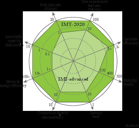
Figure 3 - Key Capabilities IMT 2020 (5G) vs IMT 2015 Source: ITU-R M.2083.0
The chart above depicts the expected increase in capabilities of the 5G network (IMT 2020) vs the 4.5 G
network (IMT 2015). You likely have heard of peak data rates of 1 Gigabit per second (Gbps), along with
Internet-of-Things (IoT) connection density, and latency between radio and network in the millisecond
(ms) range, there are other key vectors including improved Network Energy Efficiency, Improved
Spectrum Efficiency, and increase in Mbps-per-square-meter. The big question is – when will all these
new capabilities come to fruition?
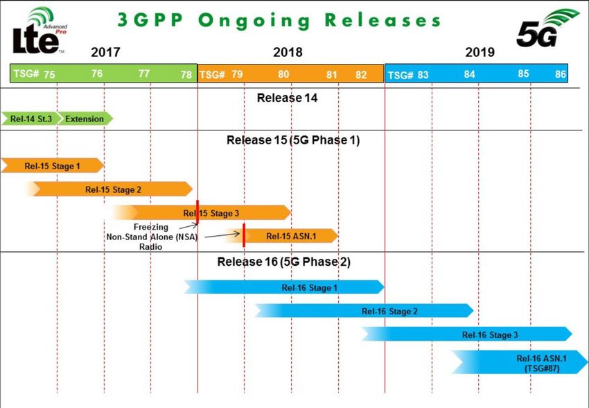
© 2017 SCTE-ISBE and NCTA. All rights reserved. 6Figure 4 - 3GPP Release Calendar Source: 3GPP.org
To answer that question, we go to the 3GPP Release Calendar, which earlier this year anticipated locking
down the 5G Standards in the middle of 2018. However, at the urging of all the large US mobility carriers
and others, the 3GPP agreed to accelerate by about 6 month the standards for Non-Stand Alone (NSA)
Radios.
This should allow silicon to be developed and integrated for initial deployment of NSA upgrades in 2019,
with the reaming standards coming to market in 2020 but likely taking a couple of years to develop scale.
One important point to note is that 4/4.5G does not go away in a 5G world, but will both interact with
support, and be supported by 5G technologies.
Now that we have reviewed some of the platform expectations of the 5G network, how do we get to Gbps
downloads with billions of connected devices?
3. 5G Spectrum and Radio Access Network (RAN) Densification
When more bandwidth is needed in a communications network there are three main levers to pull
individually or in combination to develop the increase:
1: Obtain more spectrum
© 2017 SCTE-ISBE and NCTA. All rights reserved. 72: Increase the efficiency through denser modulations allowing the transport of more bits per hertz
3: Enable the re-use of spectrum through network densification
The 5G roadmap delivers on all three, all of which the cable industry has employed going from 300 MHz
to 1 gigahertz (GHz), moving from Quaternary Phase Shift Keying (QPSK) to 256 Quadrature Amplitude
Modulation (QAM) and beyond, and performing node recombines, node splits, and service group splits
for spectrum re-use.
On the spectrum front, there are two very significant additions from the legacy cellular world:
1: Potentially using unlicensed or shared spectrum such as the 3.5 GHz Citizens Broadband Radio Service
(CBRS) in the US.
2: Employing hundreds of MHz of spectrum at very high frequencies such as 28 GHz and 39 GHz. It
should be noted that these higher frequencies are commonly called “millimeter wave”, however only the
39 GHz spectrum has sub-centimeter wavelength of ~7.6 millimeters (mm).
Figure 5 - Spectrum by Carrier US Source: Sprint
© 2017 SCTE-ISBE and NCTA. All rights reserved. 8The figure above reflects approximate spectrum of the 4 major US carriers reflecting population-
weighting (how much spectrum per average person) versus geographic coverage. Each of the spectrum
areas are broken up in a number of blocks/channels, ranging from 10 to 30 MHz in width that are
continually reused in alternating cells. Though mileage may vary, for the purposes of providing
bandwidth scoping and to make the math easy we will assume throughput on the order of 5 bits per hertz,
so a 10 MHz channel would support ~50 Mbps, a 20 MHz 100 Mbps, etc. By aggregating channels
together, the carriers are able to deliver higher total throughput, but the challenge for handset
manufacturers is adding more antennas and tuners while managing battery life.
The chart below provides the licensee status of the cellular spectrum blocks in the top 3 US Markets.
Figure 6 - Cellular Block Licenses – top 3 US markets Source: FCC
The new cm/mm frequency blocks are where significant bandwidth can be added – the 28 GHz block
goes from 27.5 to 28.35 GHz, and the 39 GHz block goes from 38.6 to 40 GHz with some license holders
having as much as 600 MHz in certain cities. Though there is a lot of bandwidth in these bands, they are
not without challenges. Higher frequency signals do not propagate as far, cannot penetrate buildings well,
and are reflected more easily than the lower-band cellular channels. (For you cable folks that remember
rain fade on Community Antenna Relay System (CARS) Band microwave links, these cm/mm wave
frequencies “enjoy” tree fade and a simple brick/stud/sheetrock wall can introduce ~30dB of attenuation).
Innovative players like Vivint have developed platforms in the 28 GHz spectrum that use a hybrid
approach – a high bandwidth point-to-point link is established between a tower or other transmitter
location to a rooftop of a “hub” – a home with clear line-of-sight to the tower and an owner willing to
allow antennas to be place on the roof (typically in exchange for free internet) which then can serve as
many as 24 other homes via 5 GHz Wi-Fi. This example demonstrates two key concepts in the coming
5G world:
1: 5G will serve fixed as well as mobile applications
2: Creative uses of multiple frequencies will be commonplace and enabled by the 5G environment. In
fact, 5G can and will be used in low, mid, and high band legacy cellular frequencies either in tandem or
standalone from the cm/mm bands.
A third concept is important to understand – the “brain” that will allow all these different bands,
applications, and systems to interoperate in a sub-millisecond latency environment by definition cannot be
back at the core as in the legacy cellular networks connected to the Mobile Telephone Switching Office
(MTSO) – it must be near the edge, be able to cache data, and have significant localized intelligence. 5G
proposes to solve this challenge with a combination of Software Defined Networking (SDN) and Network
Functions Virtualization (NFV). These technologies will enable a multi-level network with autonomous
local routing directed from a SDN controller. An example of this would be in a vehicle-to-vehicle
communications system instead of the packets having to go from car to tower to MTSO to tower to car,
© 2017 SCTE-ISBE and NCTA. All rights reserved. 9the Remote Radio Head (RRH) would have the SDN-enabled capability to connect the two vehicles
locally.
4. The 5G PAC (Power, Attachment, Connectivity) Conundrum
In the 4G world of 2017 there are 300,000 – 350,000 classic tower/building-top cellular base stations –
known in the industry as Macros, and tens of thousands of micro, pico and femtocells Each cell site could
cover as much as several square miles to only a diameter of 1000 feet or so. In the 4G environment absent
new spectrum (and at this point not including modulation density improvements) to double the bandwidth
would require doubling the towers, but the aspirations of 5G are for a ten-times higher Mbps per square
meter – 10X! The answer is cell-densification, also known as “small cells”. How small? In some
proposals only a few hundred feet wide.
To illustrate this the example below shows a 4G “Macro” site with a 1-mile radius, and a subset of 500-
foot radius small cells.
Figure 7 - 500 foot small cells, 1 mile diameter Macro cell
Source: Broadband Advisors Group, LLC
If a 1 square mile macro site (please note a 1-mile diameter hex is not a square mile – illustrative
example) was to be fully populated with 500-foot diameter small cells – there would be more than 100 of
them, with all the ensuing challenges of power, how/where to attach to light poles, power poles, strand,
and how to get network connectivity to them. That’s not the end game for 5G – for one, the Macro site
doesn’t go away – it remains serving 4G customer and perhaps enhancing 4G performance and coverage
through 5G-enabling technologies such as the dedicated fronthaul/backhaul channel to the Macro site
employed by the Sprint Magic Box.
© 2017 SCTE-ISBE and NCTA. All rights reserved. 10If a cellular operator faces bandwidth challenges in residential areas, there are not many options if
additional spectrum is not available – current tower locations are often as close to homes as the
municipalities and residents will allow, and adding additional towers, even if a smaller monopole,
requires significant time for zoning, permitting, and a fiber extension would be required.
What if an approach modeled after outdoor Wi-Fi networks was taken that could improve bandwidth?
Keeping with our model of a 1 square mile cell, what else is roughly a square mile that the cable industry
has hundreds of thousands of? HFC Nodes. Ranging from as small as a couple tenths of a square mile in
dense urban areas to several square miles in rural zones, if one looks at road-miles-per-square mile from
state and county Departments of Transportation in suburban areas there are 5-7 road miles per square mile
– sound familiar? HFC nodes serving 500 homes passed are around 5 strand-miles.
Figure 8 – 500 foot small cells integrated with HFC network
Source: Broadband Advisors Group, LLC
The example above depicts part of node with ~500’ diameter cellular base stations overlaid. Much like
outdoor Wi-Fi deployments, these radios could solve the PAC conundrum by obtaining Power from the
HFC network, being Attached via strand mount brackets, and by obtaining Connectivity through an
embedded DOCSIS modem. Note that the overlays are not ubiquitous – one of the challenges with radio
densification is managing interference, so the HFC-connected radios would be designed to cover areas
with heavy bandwidth demand (a bus stop for example) or where coverage from the macro base needs to
be improved.
For planning purposes, we will assume the radios would be similar to outdoor wireless equipment in
terms of space, power consumption, and bandwidth – roughly the size of an amplifier or fiber splice
© 2017 SCTE-ISBE and NCTA. All rights reserved. 11closure, drawing low tens of watts, and provisioned much like a residential or commercial cable modem
with 50-100 Mbps downstream and 3-5 Mbps upstream.
In the power domain, if each radio consumed 20 watts, if 20 were deployed in a node, at 75 volts average
input the current draw would increase by 5.3 amps, in most nodes requiring the installation of an
additional power supply.
In the Connectivity domain, to make the math easy we will assume the modems are provisioned for 100
Mbps downstream (we will leave upstream out of this scenario as DS/US loads in the cellular domain are
very similar those of wireline networks – much lower than downstream) – if the Macro site was
congested, a dozen users waiting at the bus stop would have more than enough bandwidth to stream video
from the local radio.
A second benefit is Internet-of-Things devices would be able to use dramatically less transmit power as
the local radios would be hundreds of feet away versus thousands.
HFC operators would rightly be concerned about overloading their DOCSIS platforms as they were with
outdoor Wi-Fi deployments, and certainly extensive traffic analysis and modeling would need to be
undertaken prior to deployment. In this traffic modeling, as CEO of Charter Tom Rutledge has noted,
more than 70% of the bits flowing down to a smartphone actually do not flow through the cellular
network – they flow through the customers home Wi-Fi network, attached to the cable modem and then
through the DOCSIS network. The outdoor HFC-fed radios would only be supporting small volumes of
short-duration activity such as a car driving down the street with a child in the backseat streaming video
or a jogger streaming Pandora as she made her neighborhood rounds, and likely would consume traffic
much like a residential modem – adding another 20 customers in a 500 homes-passed node would not
overload a typical DOCSIS Service Group.
If this scenario was deployed, now the operators have another cellular backhaul revenue stream and the
improved cellular coverage would provide better experiences for the cable customers TV Anywhere-type
streaming via the mobility network.
As cellular densification continues and the need for bandwidth exceeds the evolving capabilities of
DOCSIS, (some 5G nodes are postulated to need as much as 80 Gbps), fiber could be extended to the
radio for connectivity with power supplied by the coax network – yet another demonstration of the
flexibility and capability of the Hybrid Fiber-Coax Architecture.
Some equipment vendors have already implemented LTE-backhaul optical circuits in their optical nodes,
and some early DOCSIS 3.1 Remote-Phy Devices (RPD) also have backhaul circuits. The current
versions provide 1 to 10 Gbps symmetrical but 80 Gbps or more is on the near-term roadmap. Where
these nodes/RPD’s are deployed, a more powerful radio consuming more bandwidth could be installed
nearby (known in the industry as a Mini-Macro) with little or no outside plant modification.
Conclusion
Now that we have reviewed the evolution of the cellular network, the forthcoming 5G augments to it, and
how the HFC network might intersect with it, what have we learned?
© 2017 SCTE-ISBE and NCTA. All rights reserved. 12• 5G - What is it? – an exciting new set of standards for wireless communications, both mobile and
fixed, that will dramatically increase connectivity speeds, support much denser end-device
connections, reduce latency, and employ new licensed and unlicensed frequencies
• 5G- Where is it? – Nowhere, but just wait…
• 5G - WHEN is it? – 2020 - with some field trials before and mass scale by 2022
• 5G - How will it be different for users and the supporting infrastructure? – Higher connectivity
speeds, lower power requirements, better support for machine-to-machine traffic, much denser
cellular radio network
• 5G - Why do we need it? – to solve the insatiable demand for higher bandwidth for smartphones,
overcome cellular spectrum challenges, enable exciting capabilities such as autonomous vehicles,
and support the explosion of Internet-of-Things connected equipment
As 5G comes to fruition, cable operators have opportunities to continue to expand the fiber-optic
backhaul for macro sites and sites that will be employing large swaths of cm/mm wave spectrum, but also
can potentially employ the HFC network for Power, Attachment, and Connectivity for cellular network
densification in the legacy cellular radio spectrum.
Abbreviations
3GPP Third Generations Partnership Project
AMPS Advanced Mobile Phone System
CBRS Citizens Broadband Radio Service
CDMA Code Division Multiple Access
DOCSIS Data Over Cable System Interface Specifications
EDGE Enhanced Data Rates for Global Evolution
ETSI European Telecommunications Standards Institute
EV-DO Evolution – Data Optimized
FDMA Frequency Division Multiple Access
Gbps Gigabit per second
GHz Gigahertz
GPRS General Packet Radio Service
GSM Global System for Mobile
HFC Hybrid Fiber-Coax
HSPA High-Speed Packet Access
IMT International Mobile Telecommunications
IoT Internet of Things
ITU International Telecommunications Union
LTE Long Term Evolution
Mbps Megabits per second
MIMO Multiple In Multiple Out
MHz Megahertz
mm Millimeter
MTSO Mobile Telephone Switching Office
NFV Network Functions Virtualization
© 2017 SCTE-ISBE and NCTA. All rights reserved. 13NSA Non-Standalone
OFDMA Orthogonal Frequency Division Multiple Access
PAC Power Attachment Connectivity
QAM Quadrature Amplitude Modulation
QPSK Quaternary Phase Shift Keying
RAN Radio Access Network
RPD Remote Phy Device
RRH Remote Radio Head
SDN Software Defined Networking
SMS Simple Message System
TDMA Time Division Multiple Access
UHF Ultra-High Frequency
Bibliography & References
Verizon/ AT&T Coverage map https://www.engadget.com/2009/11/03/atandt-sues-verizon-over-theres-a-
map-for-that-ads/; Engadget.com
Enhancement of key capabilities from IMT-Advanced to IMT-2020; ITU-R M.2083-0 International
Telecommunications Union – Radio
Spectrum by US Carrier; http://newsroom.sprint.com/in-land-wireless-spectrum-is-king.htm; Sprint
Cellular Block Licenses – Top Three US Markets; FCC – Federal Communications Commission
© 2017 SCTE-ISBE and NCTA. All rights reserved. 14You can also read