THE ONERA ELSA CFD SOFTWARE: INPUT FROM RESEARCH AND FEEDBACK FROM INDUSTRY
←
→
Page content transcription
If your browser does not render page correctly, please read the page content below
28TH INTERNATIONAL CONGRESS OF THE AERONAUTICAL SCIENCES

        THE ONERA ELSA CFD SOFTWARE: INPUT FROM
         RESEARCH AND FEEDBACK FROM INDUSTRY
                                     L. Cambier, S. Heib, S. Plot
                                  Onera – The French Aerospace Lab
                                      F-92322 Châtillon, France
                                      Laurent.Cambier@onera.fr

             Keywords: Navier-Stokes, aerodynamics, aircraft, helicopter, turbomachinery

Abstract                                             capitalization of various research results in the
                                                     elsA multi-purpose code allows in the first place
The Onera elsA CFD software is both a                the sharing of common CFD features for
software package capitalizing the innovative         simulating external flows around airframes or
results of research over time and a multi-           internal flows in turbomachinery. In the second
purpose tool for applied CFD and multi-              place, it allows the selection over the wide range
physics. The research input from Onera and           of capabilities, of the features which are best
other laboratories and the feedback from             suited to the application, since there is no
aeronautical industry users allow enhancement        universal CFD method answering all of the
of its capabilities and continuous improvement.      problems.
The paper presents recent accomplishments of         The research studies, software development and
varying complexity from research and industry        validation activities, dealing with elsA, rely on a
for a wide range of aerospace applications:          project approach necessary to cope with the
aircraft, helicopters, turbomachinery…               complexity of today’s CFD. This project
                                                     approach is coordinated by Onera and involves
                                                     input from other research laboratories and
1 Introduction
                                                     feedback from aeronautical industry. The
For about 15 years at Onera, the elsA software is    objective of the paper is to show recent
simultaneously a basis for Computational Fluid       outstanding accomplishments both from the
Dynamics (CFD) research, a software package          research side and from the industry side.
capitalizing on the innovative results of research
over time, a tool allowing investigation and
understanding of flow physics, and a multi-          2 General description of elsA
purpose tool for applied CFD and multi-physics       First, let us briefly recall the main features of
[1-4]. The range of aerospace applications           the elsA software (see a more detailed overview
covered by elsA is very wide [5]: aircraft,          in [4] and associated references). The elsA
helicopters, tilt-rotors, turbomachinery, counter-   multi-application CFD simulation platform
rotating open rotors (CROR), missiles,               deals with internal and external aerodynamics
unmanned aerial vehicles (UAV), launchers…           from the low subsonic to the high supersonic
As a matter of fact, the aerodynamic analysis        flow regime and relies on the solving of the
and design in aerospace today requires high          compressible 3-D Navier-Stokes equations. elsA
levels of accuracy and reliability which result      allows the simulation of the flow around
from studies in several domains: physical            moving deformable bodies in absolute or
modelling, numerical methods, software               relative frames. A large variety of turbulence
engineering, efficiency on rapidly evolving          models from eddy viscosity to full Differential
hardware and extensive validation by                 Reynolds Stress models (DRSM) are
comparison with experimental databases. The          implemented in elsA for the Reynolds averaged
                                                                                                      1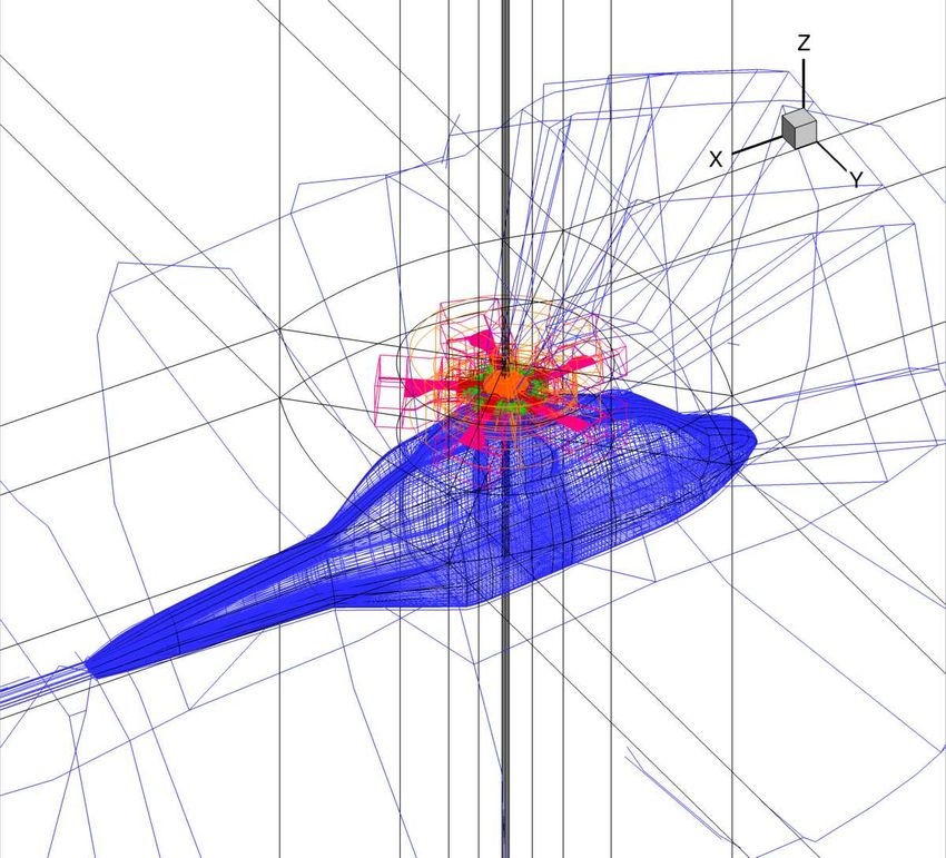
L. CAMBIER, S. HEIB, S.PLOT

Navier-Stokes (RANS) equations. Laminar-            organization (Toulouse) is an important elsA
turbulent transition modelling relies either on     partner since 2001 and has been participating
criteria, or on solving additional transport        over the last decade to research studies and
equations. Various approaches for Detached          software development dealing in particular with
Eddy Simulations (DES) and Large Eddy               mesh strategies, numerical methods and CPU
Simulations (LES) are also available.               efficiency. Other main research partners are the
Complex geometrical configurations may be           Fluid Mechanics and Acoustics lab (LMFA,
handled using high flexibility techniques           École Centrale de Lyon) and Cenaero (Belgium)
involving multi-block structured body-fitted        for turbomachinery flow simulation, and the
meshes: these techniques include patched grid       Dynfluid lab (Arts et Métiers ParisTech) for
and overset capabilities (Chimera technique).       high accuracy numerical schemes (see section 5
From this initial multi-block structured meshing    for activities about elsA by Cerfacs, LMFA,
paradigm, elsA is presently evolving toward a       Cenaero and Dynfluid). The Von Karman
quite complete multiple-gridding paradigm           Institute also uses elsA for turbomachinery flow
including the local use of unstructured grids in    simulation (see the validation study of the
some blocks of a multi-block configuration as       transport equation transition model in [6]).
well as adaptive Cartesian grids.                   Whereas it is rather unusual for a CFD software
The system of equations is solved by a cell         package to deal both with external flows around
centered      finite-volume    method.     Space    aircrafts or helicopters and with internal flows
discretization schemes include classical second     in turbomachinery, elsA is today used as a
order centered or upwind schemes and higher         reliable tool by Airbus for transport aircraft
order schemes. The mostly used integration of       configurations,     by     Safran     group   for
the semi-discrete equations relies on a backward    turbomachinery flow simulations and by
Euler technique with implicit schemes solved by     Eurocopter for helicopter applications (see
robust LU relaxation methods. The convergence       section 4). Among other users, let us mention
is accelerated by the use of multigrid techniques   MBDA for missile configurations and
for steady flows. The implicit Dual Time            Électricité de France for steam turbine
Stepping (DTS) method or the Gear scheme is         applications [7].
employed for time accurate computations.            A two-day Workshop gathering simultaneously
elsA also includes an “aeroelasticity module”       research partners and industry users is organized
offering a framework for aeroelastic simulations    every two years to share experience. The results
and an “optimization module” for calculation of     presented in the paper either are issued from the
sensitivities by linearized equation solution or    last elsA Workshop in December 2010, or
by adjoint solver techniques.                       correspond to more recent accomplishments.
elsA is based on an Object-Oriented (OO)            We will present some real-world applications
design method and is coded in three                 from the main industry users. Then, we will
programming languages: C++ as main language         show results from Onera and research partners,
for implementing the OO design, Fortran for         mostly illustrating prospects for future use.
CPU efficiency of calculation loops, Python for
the user interface. A good CPU and parallel
efficiency is reached on a large panel of           4 Results from industry users
computer platforms.
                                                    This section presents some examples of the use
                                                    of elsA by three of our main industry partners:
3 Research partners and industry users              Safran, Airbus and Eurocopter.

The development and the validation of the elsA      4.1 Turbomachinery results
software benefit by inputs from research
partners and feedback from industry users. By       Figure 1 provided by Snecma company (Safran
first considering the research side, the Cerfacs    group) shows some elsA results for modern

                                                                                                   2
THE ONERA ELSA CFD SOFTWARE:
                                                 INPUT FROM RESEARCH AND FEEDBACK FROM INDUSTRY

fans. The two curves illustrate the contribution           row simulations, and for the major part on
of the Onera CFD software (elsA in recent                  multi-stage applications. Best practice on space
years) to the simultaneous progress of the                 and time numerical schemes, turbulence and
efficiency of the conventional fans (more than             transition modelling, boundary conditions have
10 points in 30 years) and the reduction of the            been defined through comparisons with
blade number (twice less blades). Examples of              experiment and with legacy code results. The
simulations are shown for a conventional fan, a            design work includes studies on technological
counter rotating fan and a CROR.                           effects, such as rotating and non-axisymmetrical
                                            Blade number   platforms, mass flow injection or suction, casing
                                                           treatments, grooves, cooling holes.
    Efficiency
                                                           Figure 2 shows a typical result of flow
                                                           simulations performed by Snecma on a multi-
                                                           stage configuration. The approximate steady
                                                           flow calculations through multi-stage machines
                                                           are today usual in design process. In elsA, they
                                                           rely on a specific steady condition based on
         Potential
         methods                                           azimuthal averages, the mixing plane condition,
                                                           to connect two consecutive rows. This type of
                                                           simulation gives a quite good prediction of the
                          Design year
                                                           overall efficiency of a machine, even if of
 a) Evolution over time of efficiency and blade number     course it does not give any information on the
                                                           flow unsteadiness, as may be given by the more
                                                           costly Reduced Blade Count technique and
                                                           Phase-Lagged (or chorochronic) method also
                                                           available in elsA for time-periodic flows [4].
                                                           The number of mesh points for the 4-stage low
                                                           pressure turbine configuration of Figure 2 is
                                                           about 10 million. Numerical settings for the
                     Modern fan with 18 blades
                                                           steady flow simulation are the following:
                                                           second order Jameson scheme, backward Euler
                                                           implicit time integration scheme, LU-SSOR
                                                           implicit technique, multigrid convergence
                                                           acceleration. Turbulence modelling relies on
                                                           Wilcox (k,ω) model. Converged solution is
            Counter rotating fan with 10 + 14 blades       obtained on Snecma computer in less than one
                                                           day. Figure 2 presents the flow field in the
                                                           complete 8-row computational domain.
                                                           Numerical results show a good comparison with
                                                           measured static pressure on the vane walls. The
                                                           comparison of the isentropic Mach number on
                                                           one of the distributors for different span
       Counter rotating open rotor with 12 + 10 blades
                                                           locations (here shown at mid-span) is also
                                                           satisfactory.
  b) Results of elsA simulations carried out by Snecma
Fig. 1 – Contribution of CFD to improvement of
efficiency (courtesy of Safran/Snecma)
The elsA software has been strongly validated
by Onera and Safran for various turbomachinery
configurations and is today intensively used for                  a) Iso-absolute Mach number at mid-span
design studies which rely for a part on isolated
                                                                                                            3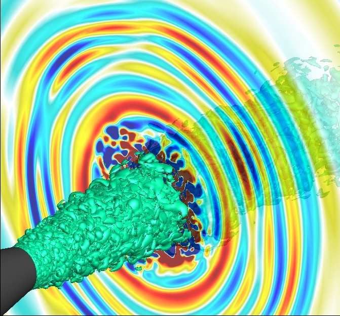
L. CAMBIER, S. HEIB, S.PLOT
Airbus today uses elsA as its structured multi-
block tool with various join types and Chimera
overset grids. There has been a massive ramp-
up of the use of Chimera technique in daily
production during the last few years. Thanks to
this technique, control surface applications are
now commonly realized with structured meshes.
This overset technique also gives to Airbus
plenty of opportunities to apply it in an easy and
fast turnaround manner: antenna on fuselage,
b) Wall static pressure (∆p = 2 000 Pa) on the hub and on wing tip effect, Vortex Generators...
the shroud : comparison with experiment
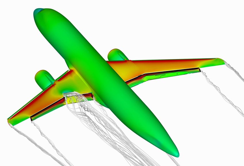
Figure 3 proposed by Airbus shows the pressure
coefficient field for a twin wing-mounted
turbofan generic transport aircraft in landing
configuration. Two calculations carried out by
the Applied Aerodynamics Department at Onera
are represented on this unique figure: without
deployment of the internal spoiler on the right,
and with deployment of the spoiler on the left.
The multi-block mesh includes more than 140
blocks and more than 33 million mesh points for
the deployed configuration. This type of
c) Isentropic Mach number on the wall of a distributor configuration is considered as very difficult to
(mid-span): comparison with experiment calculate with block-structured meshes. Thanks
Fig. 2 - Snecma results with elsA on a 4-stage to the use of Cassiopée pre-processing tools [8]
turbine (courtesy of Safran/Snecma) delivered with the elsA software suite, these
calculations illustrate the possibilities of the
elsA software is also used by other Chimera technique to deal with such
turbomachinery manufacturers of the Safran configurations. These results are considered by
group: Turbomeca for helicopter engines and Airbus of utmost importance for performance
Techspace Aero for fans and boosters. prediction of the landing configurations.
4.2 Transport aircraft results
CFD based on Navier-Stokes equations has
today reached a maturity level in terms of
accuracy, robustness and efficiency, which
makes it essential for the daily work of
aerodynamic engineers of transport aircraft
manufacturers. Navier-Stokes CFD has been
introduced for many years in Aerodynamic
Design and Data processes of Airbus with the
following objectives: Fig. 3 - Pressure coefficient calculated by elsA for a
- quickly deliver more optimized aircraft generic aircraft in landing configuration with /
components aerodynamic shapes; without internal spoiler deployed (Onera calculation)
- evaluate Reynolds effects, jet effects, ground Thanks to elsA Chimera features, Airbus is also
effects by extrapolating results known on an able to simulate the unsteady flow in a
existing aircraft; representative shape of the landing gear cavity
- prepare, analyse and, if necessary, correct of a transport aircraft (Fig. 4). A first mesh is
wind tunnel and flight tests. defined for the basic configuration including
4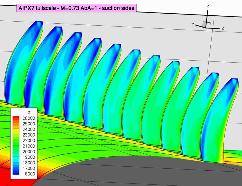
THE ONERA ELSA CFD SOFTWARE:
                                            INPUT FROM RESEARCH AND FEEDBACK FROM INDUSTRY

four Chimera domains respectively for the
cavity, for the fuselage, for the wheel and pylon
and for a triangle added plate. Then, to study the
influence of an internal spoiler, which was
proposed in order to reduce the rear door loads,
a second Chimera mesh is defined by adding to
the first mesh an internal spoiler Chimera                        a) Iso-contours of the pressure coefficient
domain. The second computation shows a high                                 on the optimized wing
rear door load reduction by putting an internal
spoiler at the middle of the cavity. The
conclusion of Airbus on this type of simulation
is positive on the ability of the Chimera strategy
to deal with complex landing gear
configurations and to quickly test additional
element effect, as well as on the elsA features
for simulating unsteady flows.

                                                            b) Evolution of the Cp distributions in sections 1 to 4
                                                                  between initial wing and optimized wing
                                                           Fig. 5 – Pilot optimization application with elsA in
                                                           full reverse mode (courtesy of Airbus)

 Basic landing gear cavity   Additional internal spoiler   4.3 Helicopter results
                                                           CFD simulation around helicopters is today
                                                           possible with a detailed representation of the
                                                           geometry which includes the rotor head with
                                                           complete mechanism. One important objective
                                                           of such simulation is to establish a drag
  Without internal spoiler     With internal spoiler       breakdown of the rotor head, element by
Fig. 4 – Landing gear cavity unsteady simulation –         element, in order to determine the most
Effect of an internal spoiler – Iso-Mach contours          important contributors to the total drag.
(green: M=0.2; red: M=0.15; yellow: M=0.1) at a            Moreover, the effect of taking into account rotor
given time (Courtesy of Airbus)                            head rotation in the CFD simulation is
                                                           determined as shown in Figure 6.
Another elsA feature appreciated by Airbus is
the full adjoint for optimum design. Figure 5
shows a pilot optimization application done in
full reverse mode. For a wing geometry
parametrisation based on 179 variables, the drag
optimization with lift kept constant allows a
drag reduction of about 3 drag counts. Figure 5
shows the evolution of the pressure coefficient
distributions in 4 sections for the initial and
optimized wings.                                           Fig. 6 – Drag breakdown given by an elsA
                                                           simulation (courtesy of Eurocopter)

                                                           Besides, this type of simulation is used for
                                                           studying the tailshake phenomenon which

                                                                                                                      5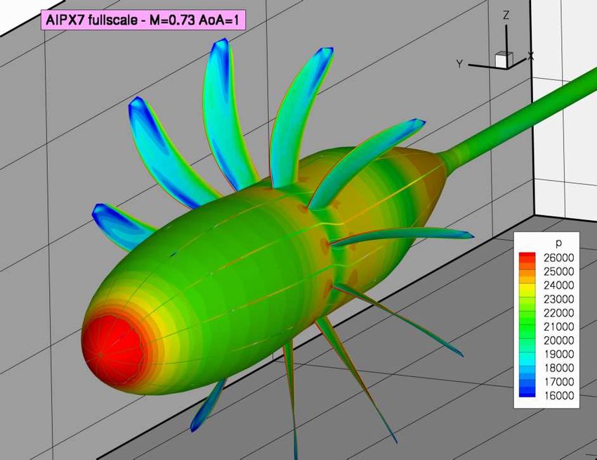
L. CAMBIER, S. HEIB, S.PLOT

corresponds to a modal excitation of the                   5 Results from Onera and research partners
structure of the rear parts of the helicopter (tail
beam, tail plane, fin) by the wake of the upper            This section presents results from Onera and
parts of the helicopter (rotor head, chimney,              research partners in order to highlight advanced
engine cowling). This type of study requires a             features on turbulence modelling, mesh
good prediction, not only of the aerodynamic               strategies, numerics and aeroelasticity.
field around the rotor head, but also of the wake
location and conservation. Figure 7 shows the              5.1 Modelling for turbulent flows
result of an unsteady elsA simulation carried out
by Eurocopter in a 36 million point mesh on 85             Whereas most of the design studies are done
processors. A second order in space numerical              with a few one- or two-equation turbulence
scheme is used. The turbulence model is the                models (Spalart-Allmaras model, (k,ω) and (k,ε)
Wilcox (k,ω) model with the SST correction.                families, (k,l) Smith model), more advanced
                                                           turbulence models for RANS equations are
                                                           studied and developed in elsA, such as the non-
                                                           eddy viscosity EARSM (Explicit Algebraic
                                                           Reynolds Stress) and DRSM models. In order to
                                                           deal with flows exhibiting strong unsteadiness
                                                           and large separated regions, LES, RANS/LES
                                                           and DES techniques are also an important elsA
                                                           research topic. We present in this section two
                                                           results of these advanced modelling techniques.
                                                           5.1.1 EARSM turbulence modelling for a
                                                           turbine flow simulation (LMFA work)
  a) Mesh of the helicopter with complete rotor head
                                                           This section presents the result of a simulation
                                                           carried out by LMFA (see [9] for another elsA
                                                           simulation by LMFA for a car turbocharger
                                                           compressor). The configuration provided by
                                                           Snecma is composed of a high pressure turbine
                                                           stage followed by the first row of the low
                                                           pressure turbine. Simulations with the (k, ω)
                                                           model predict too small losses on the low
                                                           pressure distributor, in comparison with the
                                                           experiment. The objective of the study of
                                                           LMFA was to evaluate if a more advanced
 b) Pressure isocontours and friction lines on the walls   turbulence model would offer a better
Fig. 7 – elsA simulation around an helicopter with
                                                           prediction. The considered turbulence model
complete rotor head (courtesy of Eurocopter)               has been implemented in elsA by the
                                                           Department of Modelling in Aerodynamics and
The drag prediction and the tailshake simulation           Energetics (DMAE) at Onera. It is an EARSM
both require high quality matchings between                model based on the (k, kl) two-equation model
Chimera blocks, a fine mesh in the region of the           proposed a few years ago by DMAE. The
rotor head wake and high quality numerics.                 turbulence closure is no more based on the
Whereas the elsA simulation today provides                 Boussinesq assumption as for the basic (k, kl)
with an accurate drag prediction, further                  model, but on a non-linear relation between the
improvement, such as the use of higher order               Reynolds tensor and the mean velocity gradients
schemes and interpolations, is necessary for a             through the Wallin-Johansson expression of the
deeper understanding of the tailshake physics.             anisotropy tensor.

                                                                                                         6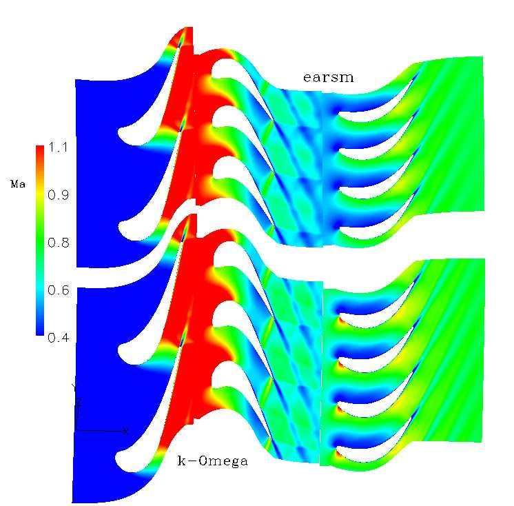
THE ONERA ELSA CFD SOFTWARE:
                                              INPUT FROM RESEARCH AND FEEDBACK FROM INDUSTRY

Figure 8a shows a comparison of the flow fields         simulation presented here and detailed in [10]
obtained by the (k, ω) model (below) and the            corresponds to a wall-to-wall swept wing
EARSM model (above). On the prediction of               configuration equipped with a pylon and an air
losses (Fig. 8b), the comparison with experiment        supply stick, and studied in transonic flow
shows an improvement with the EARSM model.              conditions in the S3Ch wind tunnel of Onera
There is still an under-estimation of the losses,       Meudon. The modelling [10] relies upon
which may be attributed to the unsteady rotor-          evolutions of the Zonal DES approach and upon
stator interaction effects, which were not taken        a turbulent Random Flow Generation (RFG)
into account in the steady simulation.                  technique. This RFG technique intends to
                                                        represent the important turbulence levels which
                                                        come from engines and which have a strong
                                                        influence on the jet development. The grid is
                                                        composed of about 175 million cells, mostly
                                                        concentrated into the jet development region
                                                        thanks to the patched-grid technique. Numerics
                                                        is ordinary: second order in space centered
                                                        scheme, second order in time Gear scheme with
                                                        Newton sub-iterations, implicit LU-SSOR
                                                        technique in each sub-iteration.

       a) Iso-absolute Mach number at mid-span

                                                        Fig. 9 – ZDES elsA simulation with the RFG
                                                        technique: instantaneous Mach field at mid-span on
                                                        the JEDI configuration (Onera simulation from [10])
                                                        The computed instantaneous Mach flow field at
                                                        mid-span (Fig. 9) shows the correct
                                                        development of the shear layers as well as the
 b) Losses in the low pressure distributor (∆x=∆y=2%)
                                                        complex interaction region between the pylon
Fig. 8 – elsA simulation in a turbine: comparison       and the jets.
between (k, ω) and EARSM (courtesy of LMFA and
Snecma)

5.1.2 Simulation of a jet with Zonal DES
(Onera work)
The DES-type approaches aim at combining the
accuracy and low cost of the RANS model for
attached boundary layers with the accuracy of
the LES in separated regions and far from walls.
These approaches are well adapted to installed
double flux engine configurations since they
allow for a deep analysis of turbulent structures       Fig. 10 – Averaged velocity fields at x/D=1 and 2.
inside mixing layers and of the interaction             Left: LDV measurements – Middle: ZDES without
between the pylon wake and the jet. The flow            RFG – Right: ZDES with RFG (Onera [10])

                                                                                                         7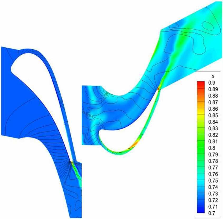
L. CAMBIER, S. HEIB, S.PLOT

Figure 10 shows a comparison with the                   simulations in parallel, for both external and
experimental averaged velocity fields of the            internal aerodynamics. Figure 11 shows the
results of two ZDES simulations with and                static pressure iso-contours given by the
without turbulence generation inside the engine.        simulation of the 3D flow around the Onera M6
The simulation with the RFG technique is in a           wing at M∞= 0.84 and α∞= 3.06°. The grid is
better agreement with experiment, but some              composed of 32 unstructured blocks and the
discrepancies remain, mostly because of the still       simulation is carried out on 32 processors. The
too low injected turbulence. Results on velocity        Spalart-Allmaras turbulence model is used.
fluctuations [10] confirm the importance of a
correct estimation of the turbulence rate of jets.

5.2 Mesh strategies
Results presented in section 4 show the
complexity of the configurations (landing gear
cavity, helicopter rotor head, turbomachinery
technological effects) which may be handled
with overset multi-block structured body-fitted         Fig. 11 – elsA simulation of the M6 wing configuration:
meshes. Nevertheless, it is very useful to have         unstructured grid and static pressure iso-contours
                                                        (Onera result from [13])
the capability of using locally unstructured
meshes in some of the blocks where it would             The second configuration corresponds to a
become too difficult to build a structured grid.        shrouded stator. The hybrid grid remains
Besides, structured Cartesian grid capabilities         structured around the blade and contains three
are well adapted to high order spatial                  additional unstructured blocks: two blocks
discretization and mesh adaptation, which in            located upstream and downstream of the blade
turn allows for better capturing of off-body flow       and one block corresponding to the cavity
phenomena such as shear layers and wakes. So,           underneath the hub. An unstructured grid
the objective of elsA is to progressively offer a       generator is able to mesh the cavity by building
quite complete multiple-gridding paradigm               only one block and in a shorter time than a
providing the potential for optimizing the              multi-block structured generator. The Wilcox
gridding strategy on a local basis for each             (k, ω) model is used.
specific configuration. We present now two
illustrations of this multiple-gridding evolution.
5.2.1 Hybrid solver (Onera/Cerfacs work)
Over the past few years, a cooperative work
between Onera and Cerfacs [11, 12, 13] has
allowed the extension of the multi-block
structured solver in elsA to an hybrid grid
solver, in which structured (ijk-based) and
unstructured blocks may coexist within the
same computational domain. Structured zones           Fig. 12 – elsA simulation in a shrouded stator : hybrid
may be kept for the sake of efficiency and of         grid (unstructured blocks in red) and flowfield
accuracy     in    viscous      layers,    whereas    (streamlines in the cavity) (Onera result from [12])
unstructured zones may enable an easier mesh
generation and adaptation process.                      5.2.2 Cartesian/curvilinear Chimera approach
Development and validation of the hybrid                (Onera work)
features in elsA are still in progress, but the two     CFD progress allows an increased use of CFD
following results show that the elsA hybrid             for aeroacoustics. The Blade Vortex Interaction
capabilities already allow turbulent flow
                                                                                                          8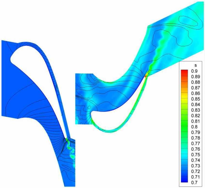
THE ONERA ELSA CFD SOFTWARE:
                                                                             INPUT FROM RESEARCH AND FEEDBACK FROM INDUSTRY

(BVI) noise, typical of helicopter applications,                                       coarse grid; see [5] for more details). When
has been selected here to illustrate this topic.                                       using a specific tool (Cassiopée Cartesian solver
The challenge is to accurately capture the                                             from Onera) which generates and automatically
evolution of the blade tip vortex during the rotor                                     adapts these Cartesian grids, and in which a
revolution. The Chimera technique allows the                                           third order in space scheme is used, it is
overlapping of a curvilinear multi-block blade                                         possible to obtain on a mesh of standard size
grid and Cartesian background grids.                                                   (Fig. 13b) the same level of accuracy as that
Three grid resolution levels have been                                                 obtained on the fine mesh without adaptation
considered for inviscid unsteady simulations                                           and with second order scheme.
performed with second order scheme. In the
finest mesh including 30 million cells, the wake                                       5.3 Numerics
is quite accurately captured with a strong vortex
intensity kept during 1.5 revolutions (only                                            Most of the elsA simulations are still done today
during 0.5 revolution with the coarse grid),                                           by second order centered or upwind space
which is necessary for the interaction with the                                        numerical schemes. Nevertheless, the increasing
following blades (Fig. 13a).                                                           needs for accuracy (for example, for
                                                                                       aeroacoustics) and the objective of reducing the
                                                                                       number of mesh cells for a given accuracy are
                                                                                       strong incentives to study higher order schemes.
                                                                                       Let us present two illustrations of this topic.

                                                                                       5.3.1 RBC schemes for the flow simulation in a
                                                                                       turbine stage (Dynfluid/Onera work)
                                                                                       The Dynfluid lab in cooperation with Onera has
                                                                                       been developing a class of numerical schemes
                                                                                       called Residual-Based Compact (RBC) schemes
      a) Wake structure with the fine grid resolution                                  [14]. Second and third order RBC schemes are
                                 r/R=0.87                                              available in elsA, whereas the study of fifth
            0.12                                                                       order RBC schemes is underway. The
                             Experiment
                             elsA - Fine mesh
                             Cassiopee 3rd order + MD - Standard mesh
                                                                                       approximation is “compact” since it uses a
             0.1
                                                                                       stencil of only 3 points in each mesh direction.
                                                                                       For general curvilinear grids, a weighted
                                                                                       formulation (noted RBCi, “i” standing for
   C ZM 2

            0.08
                                                                                       “irregular”) ensures third order accuracy on
                                                                                       mildly deformed mesh and at least second order
            0.06
                                                                                       accuracy on highly deformed meshes.
                                                                                       Figure 14 shows a comparison of the results
            0.04                                                                       obtained with the RBCi scheme with respect to
                   0   15   30        45
                                      Ψ
                                                 60         75          90             those of the classical second order Jameson
b) Influence of mesh, adaptation and numerical scheme
                                                                                       scheme (see [14] for more details). Quasi-3D
  on airload fluctuations : advancing side BVI peaks                                   unsteady computations are performed on a
Fig. 13 – elsA simulation for BO105 helicopter                                         radial portion of the VKI BRITE HP transonic
rotor in descent flight (Onera calculation from [5])                                   turbine stage. The use of chorochronic boundary
                                                                                       conditions allows simulating just one blade per
The evolution of the sectional lift coefficient
                                                                                       row. The RBCi scheme provides with a sharp
CzM2 at r/R=0.87 on the advancing side (Fig.
                                                                                       capturing of shock waves and of von Karman
13b) shows that the amplitude and the phase of
                                                                                       vortices in the blade wakes, which are smoothed
all simulations are quite good with the finest
                                                                                       out by Jameson’s scheme.
mesh (no BVI oscillation is simulated by the

                                                                                                                                        9
L. CAMBIER, S. HEIB, S.PLOT

                                                   are implemented to avoid such behaviour. An
                                                   explicit Low Dissipation and Dispersion six
                                                   stage Runge-Kutta scheme (LDDRK6) is used
                                                   for time integration. The turbulence is taken into
                                                   account via a LES approach where the subgrid-
                                                   scale modelling is implicit, assuming that the
                                                   energy transfer from large scales to small scales
                                                   is provided by the filtering operation. The
                                                   approach coupling LES for aeroacoustic sources
                                                   and Ffowcs Williams – Hawkings analogy for
                                                   acoustic propagation has been used. The
                                                   classical (M = 0.9; Re = 400 000) isothermal
          a) Second order Jameson scheme           round jet has been simulated. The mesh includes
                                                   about 20 million cells, which corresponds to a
                                                   prediction up to a Strouhal number of 2.

            b) Third order RBCi scheme
Fig. 14 – Unsteady flow simulation in the VKI      Fig. 15 – Isothermal round jet LES elsA simulation:
BRITE HP turbine stage (elsA result from [14])     vorticity and dilatation fields (courtesy of Cerfacs)
5.3.2 Jet noise simulation using high order
                                                   The vorticity field (Fig. 15) shows the turbulent
LES (Cerfacs work)
                                                   character of the flow at the exit nozzle, which
The prediction of acoustics generated by a jet     results from the vortex ring perturbation applied
engine is a challenging task, due to the large     to the inlet boundary. The dilatation field (Fig.
disparity between the length and time scales of    15) perpendicular to the jet axis is a good
the flow field. To capture accurately such         indicator of the acoustic wave propagation.
disparities, it is necessary to have numerical
schemes that exhibit low dispersion and
dissipation errors. Such schemes have been
implemented in elsA [15]; they are based on a
sixth order compact finite volume formulation.
To ensure stability, a filtering operation (also
based on a sixth order compact formulation) is
necessary. The boundary conditions play a very
important role for aeroacoustic computations,
since acoustic waves reflecting on the boundary
of the domain can completely pollute the
simulation. Either non-reflecting Navier-Stokes
Characteristic Boundary Conditions (NSCBC),
or a radiation condition based on the asymptotic   Fig. 16 – Isothermal round jet simulation: spatial
solution of the linearized Euler equations [16]    distribution of OASPL (courtesy of Cerfacs).
                                                                                                     10
THE ONERA ELSA CFD SOFTWARE:
INPUT FROM RESEARCH AND FEEDBACK FROM INDUSTRY
The analysis of the overall sound pressure level The forced response is calculated in the
(OASPL), which describes the contribution of following steps. First, with the assumption of
all measured frequencies, shows that the noise the cyclic symmetry of the structure, only one
directivity is accurately captured and the sector is taken into account for the Finite
maximum error compared to experimental data Element modal analysis resulting from
is around 2 dB (Fig. 16). calculations with the Samcef code. Then, the
aerodynamic damping is estimated by the
5.4 Aeroelasticity unsteady RANS simulations performed with the
elsA solver on a single rotor passage. The Smith
(k,l) turbulence model is used. The time
The “Ael” subsystem of elsA developed by the
advancing is simulated by the DTS technique.
Aeroelasticity and Structural Dynamics (DADS)
Finally, the excitation force of 10N is predicted
Department of Onera gives access in a unified
by the elsA unsteady RANS computations with
formulation to various types of aeroelastic
the chorochronic approach for the stage
simulations. The simulation types range from
configuration shown in Figure 17.
non-linear and linearized harmonic forced
motion computations, to static coupling and
consistent dynamic coupling simulations in the
time-domain, with different levels of structural
modelling (“reduced flexibility matrix” for
static coupling, modal approach, or full finite
element structural model).
5.4.1 Investigation of compressor blade
vibrations due to subharmonic aerodynamic
excitations (Cenaero work)
Fig. 17 - Configuration to provide the 10N
The first example of an aeroelastic simulation excitation: one blade out of 10 stator blades is
(see [17] for more details) deals with the forced different (in red) (courtesy of Cenaero)
response behaviour of a compressor blisk One of the input parameters for the forced
(resulting from the manufacturing of blades and response estimation is the aerodynamic damping
disks as a single element). The one piece which is related to the flow unsteadiness
structure and the low weight of the blisk may generated by the blade dynamic motion. To
lead to poor vibrational performance that is measure the aerodynamic damping, the forced
worth being known. The aeroelastic analysis is harmonic motion corresponding to the mode 1F
performed by computing the modal properties with constant amplitude is applied to the blade.
of the structure as well as the aerodynamical This blade motion generates unsteady pressure
damping and forces acting on it. which can either excite the structure or damp it.
The forced response behaviour due to a The analysis shows that the aerodynamic
subharmonic Blade Passing Frequency damping values for this test case are positive
Excitation is studied on a blisk of a low pressure which help to avoid the flutter instabilities.
compressor, designed at Techspace Aero. The To evaluate the response of the mode 1F, the
related Campbell and ZZENF diagrams show excitation corresponding to the 10N should be
crossing of the first bending mode with 10 extracted. For this purpose, the calculated
engine orders (1F/10N). Since there are 100 Generalized Aerodynamic Forces (GAF) are
stator blades upstream of the rotor, a practical transferred to the frequency domain using Fast
solution to generate a subharmonic excitation Fourier Transform. Figure 18 presents
(10N) is to replace one out of 10 blades by a amplitude of the GAF versus the frequency. The
thicker one as presented in Figure 17. part of the GAF which shows the impact of the
11L. CAMBIER, S. HEIB, S.PLOT
thicker blade (10N) and the part of all stator blade model of the front propeller of a generic
blades (100N) is shown in the figure. CROR configuration, due to an incidence effect.
The full 360o 11 blade generic propeller
configuration (Fig. 20) is meshed, leading to a
121 structured block grid, including about 14
million cells. A view of the static pressure field
computed by elsA on the rigid propeller at
cruise conditions (M∞=0.73 and α∞=1o) is
shown. In this case, due to incidence, the
flowfield is unsteady, and produces a 1/rev
periodic loading on each blade which is likely to
induce periodic forced response of soft bladings,
as shown below.
Fig. 18 - GAF signal in frequency domain (courtesy
of Cenaero)
By taking into account only the excitation
corresponding to the 10N and solving the
equation of motion of the structure, the forced
response is estimated. Figure 19 presents the
calculated amplification factor for a 10N
excitation. The comparison with the
measurements reveals that the computations
underestimate the forced response.
Fig. 20 – Unsteady elsA simulation on a generic
propeller rigid configuration (Onera simulation)
Fig. 19 - Amplification factor vs frequency for mode
In a second step, after rigid blade computations,
1F and excitation of 10N (courtesy of Cenaero).
aeroelastic dynamic fluid-structure coupled
computations have been carried out using the
5.4.2 Dynamic forced response of a soft blade Ael aeroelasticity module of elsA, in order to
propeller due to incidence effect (Onera work) study the forced response of the soft model, due
The DADS Department of Onera is in charge of to an incidence effect. A modal structural model
has been implemented, including first and
developing prediction capabilities concerning
the aeroelastic behaviour of soft blade second bending and first torsion modes at nodal
diameter 1, likely to be excited by the diameter
propellers and CRORs, in terms of flutter, whirl
flutter and dynamic response, and also for 1 loading due to incidence.
During the transient computation, several pieces
evaluation of global loads [18]. Hereafter are
presented some elsA results concerning the of information are collected: generalized
evaluation of the dynamic response of a soft coordinates and forces histories, global loads
history such as thrust or vertical force. These
12THE ONERA ELSA CFD SOFTWARE:
INPUT FROM RESEARCH AND FEEDBACK FROM INDUSTRY
data are post-processed in order to extract the Further improvements are still requested for
frequency response in terms of blade satisfying the demand for better physical
deformation and forces: 1/rev forced response modelling (for the simulation of detached
deformation and force levels are extracted, as flows), for more accuracy (for example, for
well as aeroelastic modal dampings. Such an aeroacoustics), for more efficiency (to deal with
analysis, performed at the same cruise the very fine meshes requested for simulating
conditions, is presented in Figure 21. The 1/rev detached flows), for faster response times (for
forced response peak is visible, as well as even more intensive use in design loops or
broader peaks at modal frequencies, illustrating optimization loops). The feedback of industry
damped modes. users on real-world configurations and the help
of research partners to carry out the future
enhancements are more than ever necessary to
cope with all these challenges.
Acknowledgements
We want to acknowledge the following
contributions to the paper: Snecma (Safran group)
for section 4.1, Airbus for section 4.2, C. François
(Onera) for the landing aircraft simulation,
Eurocopter for section 4.3, G. Ngo Boum (LMFA)
for the EARSM turbine simulation, V. Brunet
(Onera) for the ZDES jet simulation, M. de la Llave
Fig. 21 – Second bending response in time and Plata and M.-C. Le Pape (Onera) for the
frequency domains at 1o angle of attack (Onera simulations in hybrid grids, T. Renaud (Onera) for
simulation) the Cartesian/curvilinear rotor simulation, B. Michel
(Onera) and P. Cinnella (Dynfluid) for RBC results,
Fluid-structure dynamic coupling simulations H. Deniau (Cerfacs) for the high order LES jet noise
are conducted with elsA/Ael over 10 full simulation, F. Thirifay (Cenaero) for the blisk forced
propeller rotation cycles, using the Spalart- response and A. Dugeai (Onera) for the propeller
forced response.
Allmaras turbulence model. The DTS scheme is
Many thanks also to all those who have made elsA
used. Simulations are run in parallel on a Linux software project so successful for many years!
Xeon cluster using 44 processors, for about 5
days.
Investigations continue on this configuration, References
especially concerning the development of whirl
flutter prediction capabilities for propellers as [1] Cambier L and Gazaix M. elsA: an efficient Object-
Oriented solution to CFD complexity. 40th AIAA
well as CROR models. ASM, Reno, AIAA Paper 2002-0108, 2002.
[2] Gazaix M, Jollès A and Lazareff M. The elsA Object-
Oriented tool for industrial applications. 23rd ICAS
6 Concluding remarks meeting, Toronto, 2002.
[3] Cambier L and Veuillot JP. Status of the elsA
The wide range of applications both from Software for Flow Simulation and Multi-Disciplinary
industry users and from Onera and research labs Applications. 46th AIAA ASM, Reno, AIAA Paper
shows that the elsA software has reached a high 2008-0664, 2008.
level of maturity, even we were not able to [4] Cambier L, Gazaix M, Heib S, Plot S, Poinot M,
Veuillot JP, Boussuge JF and Montagnac M. An
show all the covered fields, such as CFD and
Overview of the Multi-Purpose elsA Flow Solver.
wind tunnel synergy [19], car turbochargers [9], Aerospace Lab, Issue 2, 2011.
steam turbines [7], wind turbines, missiles, [5] Reneaux J, Beaumier P and Girodroux-Lavigne P.
launchers… Advanced Aerodynamic Applications with the elsA
Software. Aerospace Lab, Issue 2, 2011.
13L. CAMBIER, S. HEIB, S.PLOT
[6] Babajee J, Arts T. Investigation of the laminar [18] Dugeai A, Mauffrey M and Sicot F. Aeroelastic
separation-induced transition with the γ-Reθt capabilities of the elsA solver for rotating machines
transition model on one very high-lift low-pressure applications. IFASD, Paris, 2011.
turbine (T2) and one engine-like scale low-pressure [19] Mouton S, Lyonnet M and Le Sant Y. Prediction of
turbine (TX) rotor blades at steady conditions and the aerodynamic effect of model deformation during
freestream turbulence. 47th 3AF Int. Symp. of Applied transonic wind tunnel tests. 47th 3AF Int. Symp. of
Aerodynamics, Paris, 2012. Applied Aerodynamics, Paris, 2012.
[7] Stanciu M, Fendler Y and Dorey JM. Unsteady
stator-rotor interaction coupled with exhaust hood
effect for last stage steam turbines. 9th European Copyright Statement
Turbomachinery Conf., Istanbul, 2011.
[8] Péron S and Benoit C. A Python module for Chimera The authors confirm that they, and/or their company or
assembly. 10th Overset Grid Symposium, organization, hold copyright on all of the original material
http://www.onera.fr/dsna/cassiopee/images/2010-09- included in this paper. The authors also confirm that they
OversetGridConnector.pdf, NASA Ames, Moffett have obtained permission, from the copyright holder of
Field, 2010. any third party material included in this paper, to publish
[9] Tartousi H, Kulisa P, Leboeuf F, Ngo Boum G, it as part of their paper. The authors confirm that they
Lefebvre A and Yammine A. Numerical investigation give permission, or have obtained permission from the
of a turbocharger centrifugal compressor: volute copyright holder of this paper, for the publication and
influence on the performance of the compressor. 9th distribution of this paper as part of the ICAS2012
European Turbomachinery Conf., Istanbul, 2011. proceedings or as individual off-prints from the
[10] Brunet V. Random flow generation technique for proceedings.
civil aircraft jet simulations with the ZDES approach.
4th Symp. on Hybrid RANS-LES methods, Beijing,
2011.
[11] Puigt G, Gazaix M, Montagnac M, Le Pape MC, de
la Llave Plata M, Marmignon C, Boussuge JF,
Couaillier V. Development of a new hybrid
compressible solver inside the CFD elsA software.
20th AIAA CFD Conf., Honolulu, AIAA Paper 2011-
3379, 2011.
[12] de la Llave Plata M, Couaillier V, Le Pape MC,
Marmignon C. elsA-Hybrid: an all-in-one structured /
unstructured solver for the simulation of internal and
external flows Application to turbomachinery. 4th
EUCASS Conf., Saint-Petersburg, 2011.
[13] de la Llave Plata M, Couaillier V, Marmignon C, Le
Pape MC, Gazaix M and Cantaloube B. Further
developments inthe multiblock hybrid CFD solver
elsA-H. 40th AIAA ASM, Nashville, AIAA Paper
2012-1112, 2012.
[14] Michel B, Cinnella P and Lerat A., Multiblock
residual-based compact schemes for the computation
of complex turbomachinery flows. IJESMS, Vol. 3,
Nos. 1/2, pp. 2-15, 2011.
[15] Fosso-Pouangué A, Deniau H, Sicot F and Sagaut P.
Curvilinear finite volume schemes using high order
compact interpolation. Journal of Computational
Physics, 229(13): 5090-5122, 2010.
[16] Fosso-Pouangué A, Deniau H, Lamarque N, and
Poinsot T. Comparison of outflow boundary
conditions for subsonic aeroacoustic simulations.
International Journal for Numerical Methods in
Fluids, 2012.
[17] Mesbah M, Thomas JF, Thirifay F, Viguie R, Durieu
F, Iliopoulou V and De Vriendt O. Investigation of
compressor blade vibrations due to subharmonic
aerodynamic excitations. 13th ISUAAAT, Tokyo,
2012.
14You can also read