TI DLP Pico Light Control - Low cost 3D printing and scanning accessories June 2021 - Low cost 3D printing and ...
←
→
Page content transcription
If your browser does not render page correctly, please read the page content below
TI DLP® Pico™ Light Control
Low cost 3D printing and scanning accessories

June 2021

                                                1
2021 Light Control Webinar Agenda
❑ DLP Pico Light Control overview
❑ DLP 3D Printers
   ▪ DLP 3D printer benefits / how it works
   ▪ Introducing the new DLP 3D print chipsets
   ▪ DLP 3D printer overview
   ▪ High level design considerations
❑ DLP 3D Scanners
   ▪ DLP 3D scanner benefits / how it works
   ▪ Applications
   ▪ Light control chipsets overview
   ▪ 3rd party offerings
❑ Ecosystem / resources

                                                 2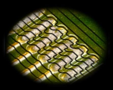
2021
    TI DLP Products | a history of innovation                                                                                                                              DLP 3D printing
                                                                                                                                                                           expands into
                                  1998              1999                                                           2015                                                    consumer market
                                                                                              2012                 Dr. Hornbeck receives
                                  DLP Products
                                                    Star Wars: Episode   2009                 DLP Industrial       the 2014 Scientific and
                                  receives first
                                  Emmy® Aw ard
                                                    1 – The Phantom      Consumer devices     dev elopment kit     Technical Academy                2017
                                                    Menace shown on      ship featuring DLP   launches allowing    Aw ard® of Merit
                                  for Outstanding                                                                  (Oscar® statuette) for           Lincoln Continental,
                                                    DLP Digital Cinema   Pico™ technology     developers to
                                  Achievement In                                                                                                    first automobile
               1996               Engineering                            based proj ectors    use DLP technology   the invention of DMD
                                                                                                                   technology as used in            w ith DLP
                                                                                              in new markets
1987           First commercial
               DLP systems
                                  Development                                                                      DLP Cinema ® projection
                                                                                                                   Photo credit: Michael Yada /
                                                                                                                                                    technology based
                                                                                                                                                    HUD
                                                                                                                   ©A.M.P.A.S.
Dr. Larry
Hornbeck
inv ents DLP
technology

                                                                                                                                                                           First 4K UHD
                                                                                                                                                                           proj ector w ith
                                                                                                                                                                           MSRP < $2000
                                                                                                                                                                           with DLP 4K
                                                                                                                                                                           UHD chipset
               For more than three decades, award-winning DLP Product                                                                             First automotiv e-
                                                                                                                                                  qualified DLP chipset
                   innovations have solved some of the world’s most                                                                               for head-up display
                                                                                                                                                  (HUD) applications
                     complex display and light control applications
DLP Pico - Display & Light Control
     Capture             Display     Print
      3D / Spectral       2D / 3D     3D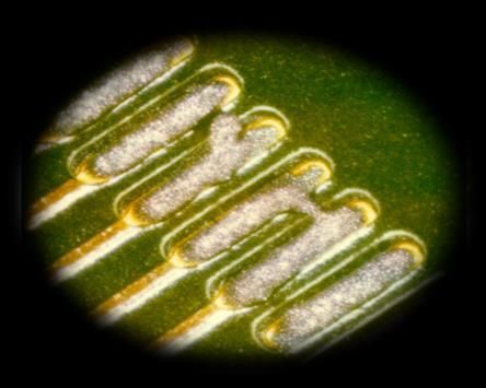
How DLP Technology works

             Array of micromirrors that digitally switch to steer light.
DLP 3D Printers

                  6
New DLP 3D Print Chipsets
  Factory floor performance, at desktop prices

Desktop DLP 3D printing:

 Ultra fast print speeds
 High efficiency and output
 Full layer exposure

 Fine detail, high accuracy
 Focused images on resin
 Small features, smooth surface finish

 Built to perform
 Based on technology used in $100,000+
 industrial DLP 3D printers
DLP 3D Printers | System and benefits
                                             Desktop DLP 3D printing means:
                         Build platform      ❑ Fast print speed
                         3D printed object      ▪ Print a full layer at a time
                         Resin Vat              ▪ High optical efficiency and output

                         Resin
                                             ❑ High resolution
                     Transparent Window
                                                ▪ DMD speed + pixel actuation
                                                ▪ Focused image on resin

                     Projection Optics
                                             ❑ Reliable operation at 405nm
                                                ▪ Inherent to DLP technology
                                                ▪ Based on technology used in:
                                                    ▪ PCB lithography
                     DMD                            ▪ Industrial 3D printers

                                                                                       8
DLP4710LC Chipset | Overview
                       Chipset                                                               Features
  DLP4710LC DMD           2x DLPC3479 controllers         ❑ Functionally equivalent – DLP4710, DLP4711
                                                          ❑ Process improvements – for light control applications
                                                          ❑ High resolution 2.1 MP – Focused optics, high accuracy

                System highlights                                                    System block diagram
                                                                                                            Parallel RGB
❑ Functionally equivalent, drop-in replacement to:
     ▪ DLP4710
     ▪ DLP4711
                                                                 3D slicing                                    DLP4710LC
❑ Fast DMD switching speed                                                                  System level         chipset
❑ 3rd party optical modules and systems available today       Image transfer                 controller
                                                                 (WiFi, USB, etc.)                             UI / Display
❑ Specified wavelengths: 420-700nm
                                                              Frame memory                                    Z-motor drive
                                                                    Legend
                                                                  TI       System
                                                                chipset     block

                                                                                                                           9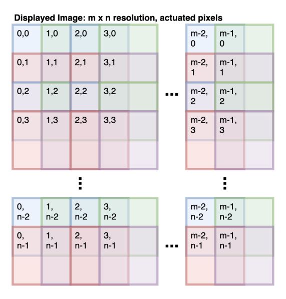
DLP300S Chipset | Overview
                     Chipset                                                                    Features
    DLP300S DMD         DLPC1438 controller             ❑ Fast printing speed – Print a full layer at a time
                                                        ❑ Reliable operation at 405nm – >3x output vs RGB LCD
                                                        ❑ High resolution 3.6 MP – Focused optics, high accuracy

               System highlights                                                           System block diagram
                                                                                                              SPI
❑ Enables
DLP301S Chipset | Overview
Chipset Features
DLP301S DMD DLPC1438 Controller ❑ Fast printing speed – Print a full layer at a time
❑ Reliable operation at 405nm – >14x output vs RGB LCD
❑ High resolution 3.6 MP – Focused optics, high accuracy
System highlights System block diagram
SPI
❑ Enables low cost, high performance DLP 3D printers Front-end FPGA
▪ Low cost SPI bus instead of parallel RGB 3D slicing
Parallel
❑ 3.6 MP solution in higher power package
▪ Increased print speed and material capabilities Image format I2C DLP301S
3D printer
chipset
❑ Fast DMD speed and 4-way actuator system
Image transfer controller
▪ For high accuracy resolution and smooth prints (WiFi, USB, etc.) UI / Display
❑ TI reference designs will be available: Frame memory Z-motor drive
▪ DLP subsystem electronics & optics
▪ Reference code: Legend
TI TI System Actuator
❑ Image formatting reference chipset block
❑ Actuator logic
11Desktop 3D print chipsets overview*
*Specifications are targets and subject to change
DLP300S
DLP4710LC Future
DLP301S
Availability Today In Progress In Progress
Resolution 2.1 MP 3.6 MP ≥ 3.6 MP
Wavelength 420 – 700 nm 400 – 550 nm 400 – 550 nm
123D Printer System block diagram
SPI
Front-end FPGA
3D slicing
Parallel
Image format I2C
DLPC1438 DLP300S/DLP301S
3D printer system
controller
Image transfer
(WiFi, USB, etc.) UI / Display
Frame memory
Z-motor drive
Legend
TI TI System
Actuator
reference chipset block
133D Printer operation timeline
Illumination Off Illum. Illumination Off Illum. Illum.
System_Ready Illumination Off
On On On
DLP controller
Command: Print Layer
Command: Print Layer
Ready for parallel data
Mode: External Print
Layer print finished
Layer print finished
Layer print starting
Mode: Standby
…
1: Send 2: Send 3: Send 4: Send 5: Send 6: Send 7: Repeat 8: Send 9: Send
Host mode first layer Start print layer next layer print layer 5-6 for all Stop mode
command data command command data command layers command command
FPGA
Vsync
Printing Setup Layer 1 Between Layers Layer 2 Layer N Print Complete
14High resolution with actuated pixels on resin
Input image: 2560 x 1440 4 Subframes: 1280 x 720 Displayed image: 2560 x 1440
❑ Same concept as modern displays – optimized for 3D printing
❑ Print 4 times the number of addressable pixels with no slow down in print speed
❑ TI will provide easy reference design to get from input resolution to projected images
15LED operation during actuation
Actuator
Position Position A Position B Position C Position D
LED LED off LED on
Actuator
Movement
Transition Stable
16DLP 3D Print with Grayscale
More accurate prints by taking advantage of every pixel
❑ DLP 3D printers have light in focus on resin
▪ Unlike LCD pixels, which blur together
❑ DLP 3D printers can print exactly what you project
▪ Smooth, round curves
▪ Sharp edges and defined points
❑ Use soft grayscale edges for smooth surfaces
▪ 8-bit grayscale available
▪ Selectable gamma curves for optimization
17DLP 3D scanners
18DLP Light Control | 3D scanner system overview
Wavelength - 405*nm – 2000nm
Time and space
DLP pattern
Transmitter coded patterns
projector
Processor
3D point cloud CCD/ CMOS
3D Object
Receiver
sensor
3D Scanner *405nm DMD in developmentDLP Light Control | DLP technology benefits
Enabling high resolution 3D capture Why choose DLP technology?
2. Object distorts the
light patterns
DLP Technology
Design Benefit
Feature
Is PCB defect-
free? (Pre-IC High speed pattern rates Real-time 3D acquisition
placement)
Flexible pattern control Micron-level accuracy & resolution
1. DMD projects light 3. Camera captures
the distorted images
External triggers Easy sync to cameras
patterns
DLP chipset Triangulation base
Illumination agnostic Works with LED, lasers & lamps
End equipment examples
Extended wavelength Diverse applications (UV, VIS, & NIR)
Factory Dental/medical Industrial/metrology Scalable portfolio Design scalable solutions (lo/mid/hi)
automation ScannersDLP Light Control | 3D scanner sub-system
SPI Optics
Flash
I2C Display and DMD
Application light control DLPxxxx
Sub-LVDS
processor controller
Video DLPCxxxx
SPI
+V System PMIC
power DLPAxxxx LEDs
Data & video signals Power signals
DLP components Other components DMD & LED cablesDLP Light Control | 3D machine vision opportunities
Prosumer 3D Industrial/metrology Inline automated
Scan + display scanner
Medical 3D scanner
scanner optical inspection
Use cases Use cases Use cases Use cases Use cases
• Retail AR • 3D Modeling • Implant surgery • Quality control • PCB solder paste &
• Projection mapping • Scan-to-print • Mouth rehabilitation • Factory automation assembly inspection
• Smart lighting • 3D animation • Dental scans • Tool Inspection • Advanced IC packaging
• Human-machine • EPOS (biometrics) • Hearing aid • In-process inspection • Machined parts
interface (HMI) • Reverse engineering inspection
image © Shining3D image © Shinning3D image © Zividlabs
image © Light Guide Systems
image © Planmeca
image © eSunNew DMD part numbers | DLPC347x
❑ The DLPC347x display and light control controllers, now have new DMD part numbers
❑ These DMDs are keyed to work specifically with DLPC347x controllers
❑ Programmed for use in light control applications (3D machine vision, 3D printing, etc.)
❑ LC DMDs are functionally equivalent to display DMDs
❑ The overall benefit is better support for light control customers:
▪ Helps support longer life cycle requirements for industrial, professional and medical markets
▪ Helps drive future developments for light control markets, independent of display markets
Controller Old DMD GPN New DMD GPN Light Control DMDs supported (future)
DLPC3470 DLP2010 DLP2010LC ▪ SW v7.x.x DLPC347x and earlier work with old DMD GPNs
DLPC3478 DLP3010 DLP3010LC
▪ New SW releases only support new DMD part numbers
DLP4710
DLPC3479 DLP4710LC ▪ DLPC347x customers should migrate to the new part numbers
DLP4711
23DLP Light Control | Pico light control chipset
DLP4500 DLP2010LC DLP3010LC DLP4710LC
DLPC350 DLPC3470 DLPC3478 DLPC3479 x 2
Chipsets →
Array size | Diagonal 912 ×1140 | 0.45” 854 x 480 | 0.2” 1280 x 720 | 0.3” 1920 x 1080 | 0.47”
# Of pixels 1.04 MP 0.41 MP 0.92 MP 2.07 MP
Pitch 7.6µm 5.4µm 5.4µm 5.4µm
Orientation ◆ diamond ◼ orthogonal ◼ orthogonal ◼ orthogonal
Max pixel data rate 2.99 Gp/s 1.02 Gp/s 2.29 Gp/s 5.15 Gp/s
2880 Hz (1-bit) 2487 Hz (1-bit) 2487 Hz (1-bit) 2487 Hz (1-bit)
Max pattern rate
120 Hz (8-bit) 272 Hz (8-bit) 272 Hz (8-bit) 437 Hz (8-bit)
DLP4500AFQD
Orderable part DLP2010LCFQJ DLP3010LCFQK DLP4710LCFQL
DLP4500AFQE
numbers DLPC3470CZEZ DLPC3478CZEZ DLPC3479CZEZ
DLPC350ZFF
Chipset price (1ku) ~$216 ~$62 ~$90 ~$190
EVM part numbers DLPLCR4500EVM DLP2010EVM-LC DLP3010EVM-LC DLP4710EVM-LCDLP Light Control | Pico EVM and TI design portfolio
Visit Design and Development portal to find the right EVM for your application
Ultra-mobile,
Mobile low power Compact high resolution
Ultra-low power
DLP2010LC DLP3010LC DLP4500 DLP4710LC
TIDA-080001 TIDA-080003 DLP4500-C350REF TIDA-080005
DLP2010EVM-LC DLP3010EVM-LC DLPLCR4500EVM DLP4710EVM-LCDLP Light Control | Pico system level modules
DLP2010LC/
Chipset DLPC3470
Applications
Robotics Dental
Scanner Factory 3D Printer
Automation Companion
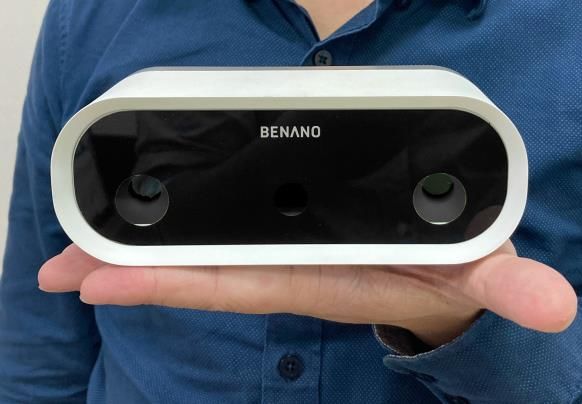
Engaging ❑ Original Design Manufacturer (ODM)
❑ System integrator
with BENANO ❑ Design services
https://www.ti.com/tool/BENANO-3P-C2100
Available through
TI.com
Simplify & accelerate development path with system level solution from 3 rd party design partners 26DLP Light Control | Pico system level modules
DLP3010LC/
Chipset DLPC3478
Applications
Robotics Dental
Scanner Factory 3D Printer
Automation Companion
Engaging ❑ Original Design Manufacturer (ODM)
❑ System integrator
with Polyga ❑ Design services
https://www.ti.com/tool/POLYGA-3P-3DEVM3010
Available through
TI.com
Simplify & accelerate development path with system level solution from 3 rd party design partners 27DLP Pico business model
Optical engine System integrators
OEMs / Brands
Manufacturers / ODMs
Controller & PMIC
DMD
Chip maker
Actuator supplier
Variety of sizes,
resolutions, and
Actuator brightness levels
Design support Design support Integration support Business facilitator2021 Light Control Webinar Summary
❑ DLP Pico Light Control overview
❑ DLP 3D Printers
▪ DLP 3D printer benefits / how it works
▪ Introducing the new DLP 3D print chipsets
▪ DLP 3D printer overview
▪ High level design considerations
❑ DLP 3D Scanners
▪ DLP 3D scanner benefits / how it works
▪ Applications
▪ Light control chipsets overview
▪ 3rd party offerings
❑ Ecosystem / resources
29Thank you
30IMPORTANT NOTICE AND DISCLAIMER
TI PROVIDES TECHNICAL AND RELIABILITY DATA (INCLUDING DATASHEETS), DESIGN RESOURCES (INCLUDING REFERENCE
DESIGNS), APPLICATION OR OTHER DESIGN ADVICE, WEB TOOLS, SAFETY INFORMATION, AND OTHER RESOURCES “AS IS”
AND WITH ALL FAULTS, AND DISCLAIMS ALL WARRANTIES, EXPRESS AND IMPLIED, INCLUDING WITHOUT LIMITATION ANY
IMPLIED WARRANTIES OF MERCHANTABILITY, FITNESS FOR A PARTICULAR PURPOSE OR NON-INFRINGEMENT OF THIRD
PARTY INTELLECTUAL PROPERTY RIGHTS.
These resources are intended for skilled developers designing with TI products. You are solely responsible for (1) selecting the appropriate
TI products for your application, (2) designing, validating and testing your application, and (3) ensuring your application meets applicable
standards, and any other safety, security, or other requirements. These resources are subject to change without notice. TI grants you
permission to use these resources only for development of an application that uses the TI products described in the resource. Other
reproduction and display of these resources is prohibited. No license is granted to any other TI intellectual property right or to any third party
intellectual property right. TI disclaims responsibility for, and you will fully indemnify TI and its representatives against, any claims, damages,
costs, losses, and liabilities arising out of your use of these resources.
TI’s products are provided subject to TI’s Terms of Sale (https:www.ti.com/legal/termsofsale.html) or other applicable terms available either
on ti.com or provided in conjunction with such TI products. TI’s provision of these resources does not expand or otherwise alter TI’s
applicable warranties or warranty disclaimers for TI products.IMPORTANT NOTICE
Mailing Address: Texas Instruments, Post Office Box 655303, Dallas, Texas 75265
Copyright © 2021, Texas Instruments IncorporatedYou can also read