Preparation of JetStar Wing for Use in Deicing Research - Transportation Development Centre Civil Aviation On behalf of Transport Canada
←
→
Page content transcription
If your browser does not render page correctly, please read the page content below
TP 13667E

Preparation of JetStar Wing for Use
        in Deicing Research

             Prepared for

   Transportation Development Centre
              On behalf of
              Civil Aviation

           Transport Canada

              August 2000
                                       Final Version 1.0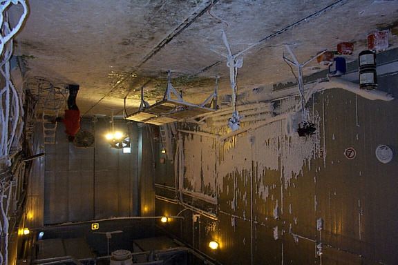
TP 13667E

Preparation of JetStar Wing for Use
        in Deicing Research

                 by

           Michael Chaput
                and
           Medhat Hanna

             August 2000

                                      Final Version 1.0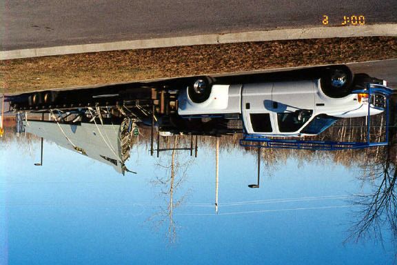
PREFACE

PREFACE

At the request of the Transportation Development Centre of Transport Canada, APS
Aviation Inc. (APS) has undertaken a research program to advance aircraft ground
de/anti-icing technology. The specific objectives of the APS test program are the
following:

•       To develop holdover time data for Type IV fluids using lowest-qualifying viscosity
        samples, and to develop holdover time data for all newly qualified de/anti-icing
        fluids;

•       To conduct flat plate holdover time tests under conditions of frost;

•       To further evaluate the flow of contaminated fluid from the wing of a Falcon 20
        aircraft during simulated takeoff runs;

•       To determine the patterns of frost formation and of fluid failure initiation and
        progression on the wings of commercial aircraft;

•       To evaluate whether the proposed locations of AlliedSignal’s wing-mounted ice
        sensors on an Air Canada CL65 are optimally positioned;

•       To evaluate the second generation of the NCAR snowmaking system;

•       To evaluate the capabilities of ice detection camera systems;

•       To examine the feasibility of and procedures for performing wing inspections with a
        remote ice detection camera system at the entrance to the departure runway (end-
        of-runway);

•       To reassemble and prepare the JetStar aircraft wing for mounting, to modify it to
        obtain cold-soak capabilities, and to conduct fluid failure tests in natural
        precipitation using the wing;

•       To extend hot water deicing tests to aircraft in natural outdoor precipitation
        conditions, and to correlate outdoor data with 1998-99 laboratory results;

•       To examine safety issues and concerns of forced air deicing systems; and

•       To evaluate snow weather data from previous winters to establish a range of snow
        precipitation suitable for the evaluation of holdover time limits.

The research activities of the program conducted on behalf of Transport Canada during
the 1999-2000 winter season are documented in nine reports. The titles of these
reports are as follows:

•       TP 13659E       Aircraft Ground De/Anti-icing Fluid Holdover Time and Endurance
                        Time Testing Program for the 1999-2000 Winter;

                                                  I:\Groups\CM1589\Reports\Wing\Final Version 1.0\Final Version 1.0 revised.doc
                                                iii                                                           Final Version 1.0
                                                                                                                   January, 02
    APS AVIATION INC.                                                                            Last printed 3/28/02 2:17 PM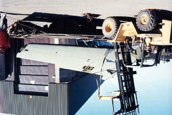
PREFACE

•       TP 13660E       Aircraft Full-Scale Test Program for the 1999-2000 Winter;

•       TP 13661E       A Second Generation Snowmaking System: Prototype Testing;

•       TP 13662E       Ice Detection Sensor Capabilities for End-of-Runway Wing Checks:
                        Phase 2 Evaluation

•       TP 13663E       Hot Water Deicing of Aircraft: Phase 2;

•       TP 13664E       Safety Issues and Concerns of Forced Air Deicing Systems;

•       TP 13665E       Snow Weather Data Evaluation (1995 - 2000);

•       TP 13666E       Contaminated Aircraft Simulated Takeoff Tests for the 1999-2000
                        Winter: Preparation and Procedures; and

•       TP 13667E       Preparation of JetStar Wing for Use in Deicing Research.

This report, TP 13667E, has the following objectives:

•       To reassemble and prepare the JetStar aircraft wing for mounting, to modify the
        wing to obtain cold-soak capabilities, and to conduct fluid failure tests in natural
        precipitation using the JetStar wing.

The JetStar wing was reassembled, the missing panels were replaced, the deicing boot
was removed, and the leading edge was polished. The wing was then mounted on a
boat trailer to hold the wing at an ideal working height and to facilitate movement and
use of the wing.

Because of the late start of the test program during the 1999-2000 winter, the cold-
soak capabilities of the JetStar wing were not examined, and no fluid failure tests using
the JetStar wing were performed.

ACKNOWLEDGEMENTS

This research has been funded by the Civil Aviation Group, Transport Canada, with
support from the US Federal Aviation Administration. This program could not have
been accomplished without the participation of many organizations. APS would
therefore like to thank the Transportation Development Centre of Transport Canada, the
Federal Aviation Administration, the National Research Council Canada, Atmospheric
Environment Services Canada, and several fluid manufacturers. Special thanks are
extended to US Airways Inc., Air Canada, National Centre for Atmospheric Research,
AéroMag 2000, Aéroports de Montreal, G. Vestergaard A/S, Hudson General Aviation
Services Inc., Union Carbide, Cryotech, BFGoodrich, Cox and Company Inc., Fortier
Transfert Ltée, and MTN Snow Equipment Inc. for provision of personnel and facilities
and for their co-operation with the test program. The authors gratefully acknowledge
the participation of Jeff Mayhew and Donald Robitaille. Special thanks are extended to
Frank Eyre and Barry Myers of the Transportation Development Centre for their
participation, contribution, and guidance in the preparation of this document. APS
would also like to acknowledge the dedication of the research team, whose
performance was crucial to the acquisition of hard data.
                                                  I:\Groups\CM1589\Reports\Wing\Final Version 1.0\Final Version 1.0 revised.doc
                                                 iv                                                           Final Version 1.0
                                                                                                                   January, 02
    APS AVIATION INC.                                                                            Last printed 3/28/02 2:17 PM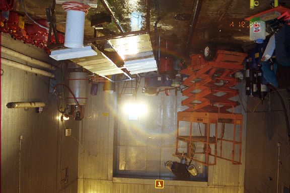
Transport        Transports
                  Canada           Canada                                                                                                        PUBLICATION DATA FORM
 1.    Transport Canada Publication No.                               2.    Project No.                                                    3.    Recipient’s Catalogue No.

       TP 13667E                                                            9789
 4.    Title and Subtitle                                                                                                                  5.    Publication Date

       Preparation of JetStar Wing for Use in Deicing Research                                                                                   August 2000
                                                                                                                                           6.    Performing Organization Document No.

                                                                                                                                                 CM1589-001
 7.    Author(s)                                                                                                                           8.    Transport Canada File No.

       Michael Chaput and Medhat Hanna                                                                                                           ZCD2450-23-14 (DC-182)
 9.    Performing Organization Name and Address                                                                                            10.   PWGSC File No.

       APS Aviation Inc.                                                                                                                         XSD-9-01714
       1100 René Lévesque Blvd. West
       Suite 1340                                                                                                                          11.   PWGSC or Transport Canada Contract No.

       Montreal, Quebec                                                                                                                          T8200-9-9563/001/XSD
       Canada H3B 4N4
 12.   Sponsoring Agency Name and Address                                                                                                  13.   Type of Publication and Period Covered

       Transportation Development Centre (TDC)                                                                                                   Final
       800 René Lévesque Blvd. West
       Suite 600                                                                                                                           14.   Project Officer
       Montreal, Quebec                                                                                                                          B. Myers
       H3B 1X9
 15.   Supplementary Notes (Funding programs, titles of related publications, etc.)

       Research reports produced on behalf of Transport Canada for testing during previous winters are available from the Transportation Development
       Centre (TDC). Nine reports (including this one) were produced as part of this winter’s research program. This subject matter is outlined in the
       preface.
 16.   Abstract

       The full-scale test site implementation study involved three phases: purchase of a wing, mounting of the wing on a
       suitable platform, and selection of an ideal test location.
       A Lockheed JetStar wing was purchased for this purpose. During the 1999-2000 winter test season, the control
       surfaces were reinstalled, a fairing was constructed for the leading edge, missing wing panels were replaced, the
       deicing boot was removed, and the leading edge was polished.
       In addition, a new mounting system for the JetStar wing, consisting of an off-the-shelf boat trailer, was proposed.
       The cost of the trailer represented a savings of more than CAN$10 000 over the cheapest quotation received in
       1999 for the mounting of the wing.
       Because the combined assembly did not conform to the Highway Code, transportation companies were contacted
       to determine the costs related to the long-distance transportation of the wing dolly assembly by means of a flatbed
       truck. Several transport companies were contacted for quotations and a company was selected.
       Full-scale testing with the JetStar wing was conducted in natural and simulated precipitation conditions at NRC
       Canada in Ottawa and at the central deicing facility at Dorval Airport in Montreal. Testing consisted of fluid
       application trials, hot water deicing trials, ice detection sensor trials for end-of-runway application, and forced air
       trials.

 17.   Key Words                                                                                         18.   Distribution Statement

       JetStar wing, wing assembly, winter operations, deicing                                                 Limited number of copies available from the
                                                                                                               Transportation Development Centre

 19.   Security Classification (of this publication)                  20.   Security Classification (of this page)                  21.   Declassification         22.    No. of    23.   Price
                                                                                                                                          (date)                          Pages
       Unclassified                                                         Unclassified                                                        —                        xiv, 46,         Shipping/
                                                                                                                                                                           app.           Handling
CDT/TDC 79-005
Rev. 96
                                                                                                   v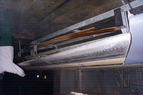
Transports         Transport
                   Canada             Canada                                                      FORMULE DE DONNÉES POUR PUBLICATION
 1.    No de la publication de Transports Canada                  2.    No de l’étude                                         3.    No de catalogue du destinataire

       TP 13667E                                                        9789
 4.    Titre et sous-titre                                                                                                    5.    Date de la publication

       Preparation of JetStar Wing for Use in Deicing Research                                                                      Août 2000
                                                                                                                              6.    No de document de l’organisme exécutant

                                                                                                                                    CM1589-001
 7.    Auteur(s)                                                                                                              8.    No de dossier - Transports Canada

       Michael Chaput et Medhat Hanna                                                                                               ZCD2450-23-14 (DC-182)
 9.    Nom et adresse de l’organisme exécutant                                                                                10.   No de dossier - TPSGC

       APS Aviation Inc.                                                                                                            XSD-9-01714
       1100, boul. René-Lévesque Ouest
       Bureau 1340                                                                                                            11.   No de contrat - TPSGC ou Transports Canada

       Montréal, Québec                                                                                                             T8200-9-9563/001/XSD
       Canada H3B 4N4
 12.   Nom et adresse de l’organisme parrain                                                                                  13.   Genre de publication et période visée

       Centre de développement des transports (CDT)                                                                                 Final
       800, boul. René-Lévesque Ouest
       Bureau 600                                                                                                             14.   Agent de projet

       Montréal (Québec)                                                                                                            B. Myers
       H3B 1X9
 15.   Remarques additionnelles (programmes de financement, titres de publications connexes, etc.)

       Les rapports de recherche produits au nom de Transports Canada sur les essais réalisés au cours des hivers antérieurs peuvent être obtenus auprès du Centre de
       développement des transports (CDT). Le programme de la saison hivernale a donné lieu à neuf rapports (dont celui-ci). On trouvera dans la préface l’objet de ces
       rapports.

 16.   Résumé

       L’étude d’implantation d’une installation d’essai en vraie grandeur comportait trois phases : achat d’une aile,
       montage de l’aile sur un support approprié et choix d’un endroit optimal pour réaliser les essais.
       Une aile de Lockheed JetStar a d’abord été achetée. Au cours de la saison d’essai 1999-2000, les gouvernes ont
       été réinstallées sur l’aile, un carénage a été construit pour le bord d’attaque, les panneaux manquants de l’aile ont
       été remplacés, le boudin de dégivrage a été enlevé et le bord d’attaque a été poli.
       Un nouveau système de montage de l’aile a en outre été proposé, soit une remorque porte-bateau du commerce.
       Le recours à une telle remorque représentait une économie de plus de 10 000 $CAN par rapport à la meilleure
       proposition de prix reçue en 1999 pour un chariot-support.
       Mais l’ensemble aile-remorque n’étant pas conforme au Code de la route, les chercheurs ont demandé des
       propositions de prix à des transporteurs routiers pour le chargement de l’aile et de son support à bord d’un fardier
       et son transport à longue distance. Après réception de multiples propositions, une entreprise a été sélectionnée.
       Des essais en vraie grandeur utilisant l’aile de JetStar ont été réalisés sous des précipitations naturelles et
       artificielles au CNRC, à Ottawa et au poste de dégivrage de l’Aéroport de Montréal-Dorval. Divers types d’essais
       ont été menés : application de fluides antigivrage, dégivrage à l’eau chaude, évaluation de détecteurs de givrage
       en bout de piste et dégivrage à air forcé.

 17.   Mots clés                                                                                     18.   Diffusion

       aile de JetStar, montage d’aile, opérations hivernales,                                             Le Centre de développement des transports dispose
       dégivrage                                                                                           d’un nombre limité d’exemplaires.

 19.   Classification de sécurité (de cette publication)          20.   Classification de sécurité (de cette page)     21.   Déclassification     22.    Nombre         23.    Prix
                                                                                                                             (date)                      de pages
       Non classifiée                                                   Non classifiée                                             —                    xiv, 46,                Port et
                                                                                                                                                          ann.                manutention
CDT/TDC 79-005
Rev. 96
                                                                                            vi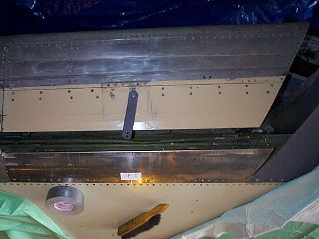
EXECUTIVE SUMMARY

EXECUTIVE SUMMARY

The full-scale test site implementation study involved three phases: purchase of
a wing, mounting of the wing on a suitable platform, and selection of an ideal
test location.

Following a long search, a Lockheed JetStar wing was purchased in April 1999.
Although not attached to the wing, all flight control surfaces were delivered
with the main wing surface. During the 1999-2000 winter test season, APS
obtained quotations for the reassembly of the various control surfaces,
construction of a fairing for the leading edge, replacement of any missing
panels, removal of the rubber deicing boot, and polishing of the leading edge.
The work was contracted to an aircraft mechanic in Ottawa.

Quotations for the design and fabrication of the wing dolly assembly were
received from several companies in 1999. During the 1999-2000 test season, a
new mounting system for the JetStar wing, consisting of an off-the-shelf boat
trailer, was proposed. Since the design of the wing mounting system did not
conform to the Highway Code, transportation companies were contacted to
determine the costs related to the long-distance transportation of the wing dolly
assembly by means of a flatbed truck. Several transport companies were
contacted for quotations and a company was chosen.

The third phase of the study involved the examination and selection of a
suitable full-scale test site. The centralized deicing facility at Dorval Airport,
operated by AéroMag 2000, was selected. NRC Canada’s Climatic Engineering
Facility was selected as the ideal location for any indoor tests in simulated
precipitation.

Additional objectives of the 1999-2000 wing test bed implementation project
included examining the integrity of the JetStar fuel system to determine wing
cold-soak capabilities and conducting fluid failure trials with the JetStar wing.
These objectives were not attained because of the late start of the test season.

During the 1999-2000 test season, full-scale testing with the JetStar wing was
conducted in natural and simulated precipitation conditions at NRC Canada in
Ottawa and at the central deicing facility at Dorval Airport in Montreal. Testing
consisted of:

     •       Fluid application trials;
     •       Testing of the Radiant Energy Corporation Deicing System;
     •       Hot water deicing trials;
     •       Use of ice detection sensors for end-of-runway application; and
     •       Forced air trials.

                                              M:\Groups\CM1589\Reports\Wing\Final Version 1.0\Final Version 1.0 revised.doc
                                             vii                                                           Final Version 1.0
                                                                                                                January, 02
 APS AVIATION INC.                                                                           Last printed 4/30/02 9:14 AM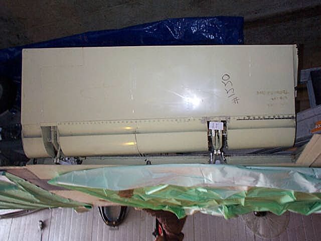
EXECUTIVE SUMMARY

Several recommendations for the improvement of the wing test bed design are
listed below and should be implemented prior to any future testing:

•        Fluid failure tests with the JetStar wing should be rescheduled for the
         upcoming test season.

•       The fuel system integrity of the JetStar wing should be examined to
        determine the feasibility of filling the tanks with fluid to obtain cold-soaking
        capabilities.

•       The structure of the trailer should be examined to potentially increase the
        overall weight capacity. Furthermore, a search for a boat trailer with
        additional weight capacity should be conducted.

•       The small swivelling wheel should be replaced by a larger inflatable wheel
        and consideration should also be given to modifying the design to include
        two retractable feet that could be extended for stability during testing.

•       A more permanent and stable method of levelling the JetStar wing should be
        examined.

•       The galvanized metal panels and fairing should be replaced with aluminum.

•       A more permanent method of securing the various control surfaces should be
        examined.

                                              M:\Groups\CM1589\Reports\Wing\Final Version 1.0\Final Version 1.0 revised.doc
                                             viii                                                          Final Version 1.0
                                                                                                                January, 02
    APS AVIATION INC.                                                                        Last printed 4/30/02 9:15 AM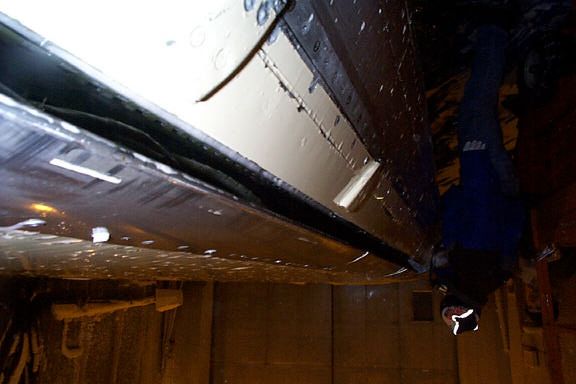
SOMMAIRE

SOMMAIRE

L’étude d’implantation d’une installation d’essai en vraie grandeur comportait
trois phases : achat d’une aile, montage de l’aile sur un support approprié et
choix d’un endroit optimal pour réaliser les essais.

Après de longues recherches, une aile de Lockheed JetStar a été achetée en
avril 1999. L’aile a été livrée avec toutes ses gouvernes, mais détachées.
Pendant la saison d’essai 1999-2000, APS a demandé des propositions de prix
pour la réinstallation des gouvernes, la construction d’un carénage pour le bord
d’attaque, le remplacement des panneaux manquants de l’aile, l’enlèvement du
boudin de dégivrage en caoutchouc et le polissage du bord d’attaque. Les
travaux ont été confiés à un mécanicien d’aéronef s d’Ottawa.

En 1999, plusieurs entreprises ont soumis des propositions de prix pour la
conception et la fabrication d’un chariot-support pour le montage de l’aile. Mais
pendant la saison d’essai 1999-2000, un nouveau système de montage a été
proposé, soit une remorque porte-bateau du commerce. Ce nouveau montage
n’étant pas conforme au Code de la route, des propositions de prix ont été
demandées à des transporteurs routiers pour le chargement de l’aile et de son
support à bord d’un fardier et son transport à longue distance. Une firme a été
sélectionnée parmi les entreprises soumissionnaires.

La troisième phase de l’étude consistait à choisir une installation d’essai en vraie
grandeur. Le poste de dégivrage de l’Aéroport de Montréal-Dorval, exploité par
AéroMag 2000, a été retenu. L'Installation de génie climatique du Conseil
national de recherches du Canada a pour sa part été choisie comme étant
l’endroit idéal pour les essais intérieurs sous précipitations artificielles.

L’année 1999-2000 du projet d’implantation d’une aile d’essai en vraie grandeur
comportait d’autres objectifs, soit l’examen de l’intégrité du circuit de carburant
de l’aile afin de déterminer ses capacités de sur-refroidissement et la conduite
d’essais de durée d’efficacité de liquides antigivrage sur l’aile de JetStar. Ces
objectifs n’ont pu être atteints en raison du début tardif de la saison d’essai.

La saison d’essai 1999-2000 a donné lieu à divers essais en vraie grandeur
mettant en jeu l’aile de JetStar menés sous des précipitations naturelles et
artificielles au CNRC à Ottawa et au poste de dégivrage de l’Aéroport de
Montréal-Dorval. Voici en quoi ont consisté ces essais :

     •       application de fluides antigivrage;
     •       essai du système de dégivrage de Radiant Energy Corporation;
     •       dégivrage à l’eau chaude;
     •       utilisation de détecteurs de givrage pour évaluer l’état de givrage des ailes
             d’un avion en bout de piste;
                                               M:\Groups\CM1589\Reports\Wing\Final Version 1.0\Final Version 1.0 revised.doc
                                               ix                                                           Final Version 1.0
                                                                                                                 January, 02
 APS AVIATION INC.                                                                            Last printed 4/30/02 9:15 AM
SOMMAIRE
• dégivrage à air forcé.
Plusieurs recommandations ont été formulées pour améliorer l’installation d’essai
d’une aile en vraie grandeur. Il conviendra de donner suite à ces
recommandations avant d’entreprendre tout autre essai. Voici la teneur de ces
recommandations :
• Que l’on réaménage le prochain calendrier des essais de durée d’efficacité
de fluides antigivrage mettant en jeu l’aile de JetStar.
• Que l’on examine l’intégrité du circuit de carburant de l’aile de JetStar afin
de déterminer la possibilité de remplir les réservoirs de liquide et de simuler
ainsi une aile sur-refroidie.
• Que l’on examine la structure de la remorque dans la perspective d’en
augmenter la capacité pondérale. Qu’une recherche soit également menée
pour trouver une remorque porte-bateau ayant une plus grande capacité
pondérale.
• Que la petite roue pivotante soit remplacée par un pneumatique à plus grand
diamètre et que l’on étudie la possibilité d’ajouter à la remorque deux pieds
télescopiques qui, déployés, aideraient à stabiliser l’ensemble pendant les
essais.
• Que l’on cherche un moyen de mettre de niveau l’aile de JetStar de façon
plus permanente et plus stable.
• Que les panneaux et le carénage en acier galvanisé soient remplacés
par des panneaux et un carénage en aluminium.
• Que l’on étudie une méthode pour fixer de façon plus permanente les
gouvernes.
M:\Groups\CM1589\Reports\Wing\Final Version 1.0\Final Version 1.0 revised.doc
x Final Version 1.0
January, 02
APS AVIATION INC. Last printed 4/30/02 9:15 AMTABLE OF CONTENTS
CONTENTS
Page
1. INTRODUCTION............................................................................................1
1.1 Objectives ...................................................................................................2
1.1.1 JetStar Wing Reassembly and Removal of the Deicing Boot.......................2
1.1.2 Mounting of the JetStar Wing on the Wing Dolly Assembly .......................2
1.1.3 Full-Scale Aircraft Tests with JetStar Wing ............................................3
1.1.4 Cold-Soak Capability of JetStar Wing ...................................................3
2. WING TEST BED PREPARATION.......................................................................5
2.1 Wing Reassembly..........................................................................................5
2.2 Wing Mounting Considerations.........................................................................7
2.3 Test Site Selection ........................................................................................9
2.4 Wing Transportation ......................................................................................9
3. LOCKHEED JETSTAR WING CHARACTERISTICS................................................23
3.1 Lockheed JetStar Wing Geometry ...................................................................23
3.2 Lockheed JetStar Fuel System Design..............................................................23
3.3 Wing Quiet Areas........................................................................................26
3.4 Main Wing and Flight Control Surface Wing Gaps ...............................................26
3.5 JetStar Wing Tests in Simulated Conditions ......................................................26
4. FULL-SCALE TESTING WITH JETSTAR WING ....................................................33
4.1 Fluid Application Trials .................................................................................35
4.2 Testing of the Radiant Energy Corporation Deicing System ...................................37
4.3 Hot Water Deicing.......................................................................................39
4.4 Use of Ice Detection Cameras for End-of-Runway Inspections................................41
4.5 Forced Air Deicing Trials ...............................................................................43
5. DISCUSSION AND RECOMMENDATIONS .........................................................45
5.1 Fluid Failure Patterns on JetStar Wing ..............................................................45
5.2 Repairs Needed to Obtain Cold-Soaking Capabilities ............................................45
5.3 Evaluation of Trailer.....................................................................................45
5.4 Mobility of Wing and Trailer...........................................................................46
5.5 Wing Surface Repairs...................................................................................46
5.6 Repair Cost Estimates ..................................................................................46
APPENDICES
A Design Characteristics of the Lockheed JetStar
I:\Groups\CM1589\Reports\Wing\Final Version 1.0\Final Version 1.0 revised.doc
xi Final Version 1.0
January, 02
APS AVIATION INC. Last printed 3/28/02 2:17 PMLIST OF FIGURES AND PHOTOS
LIST OF FIGURES
Page
2.1 Three-View Schematic of Lockheed JetStar.........................................................6
3.1 JetStar Wing Dimensions..............................................................................24
3.2 Fuel System of the Lockheed JetStar...............................................................25
3.3 Hard Wing/Flight Surface Wing Gaps ...............................................................27
3.4 JetStar Wing Inside NRC Canada Chamber........................................................28
LIST OF PHOTOS
Page
2.1 Lockheed JetStar ........................................................................................11
2.2 Truck and Trailer Used to Transport JetStar Wing ...............................................11
2.3 JetStar Wing Upon Arrival in Ottawa ...............................................................13
2.4 JetStar Wing Control Surfaces .......................................................................13
2.5 Removal of the Wing from the Transportation Vehicle..........................................15
2.6 Trailing Edge Quiet Area ...............................................................................15
2.7 Bracket Used to Secure Leading Edge Slat ........................................................17
2.8 Leading Edge Quiet Area...............................................................................17
2.9 Polished Leading Edge of JetStar Wing.............................................................19
2.10 JetStar Wing on Boat Trailer..........................................................................19
2.11 Flatbed Truck Moveable Ramp Used to Transport JetStar Wing and Wing-
Mounting System........................................................................................21
2.12 Wing and Trailer on Flatbed Truck at NRC Canada ..............................................21
3.1 Outdoor View of NRC Canada Climatic Engineering Facility ...................................29
3.2 Inside View of Small End of Climatic Engineering Facility ......................................29
3.3 Inside View of Large End of Climatic Engineering Facility ......................................31
4.1 JetStar Wing Test Set-up for Fluid Application Trials ...........................................35
4.2 Type I Fluid Application using Mobile Sprayer ....................................................35
4.3 Deicing JetStar Wing Using Conventional Deicing System From Scissor Lift..............37
4.4 Test Set-up for Hot Water Trials .....................................................................39
4.5 Snow Failure on the JetStar Trailing Edge .........................................................39
4.6 Wing Set-up at the Central Deicing Facility at Dorval Airport .................................41
4.7 Snow Accumulation on the JetStar Trailing Edge................................................41
4.8 Forced Air Deicing Set-up at NRC Canada .........................................................43
4.9 Freezing Rain on JetStar Wing Prior to Forced Air Deicing.....................................43
I:\Groups\CM1589\Reports\Wing\Final Version 1.0\Final Version 1.0 revised.doc
xii Final Version 1.0
January, 02
APS AVIATION INC. Last printed 3/28/02 2:17 PMGLOSSARY
APS APS Aviation Inc.
CEF Climatic Engineering Facility
HOT Holdover Time
IREQ Institut de recherche d’Hydro-Québec
NCAR National Center for Atmospheric Research
NRC Canada National Research Council Canada
Aerodynamically quiet areas:
There are two classes of aerodynamically quiet areas: aircraft cavities and
aerodynamic surfaces with separated airflow.
Aerodynamically quiet cavities:
All aircraft have cavities into which fluids may seep under gravity but where
drainage may be inadequate for a viscous fluid to seep out. If the cavity is not
sufficiently scoured by the airflow during take-off to effectively remove a fluid
more viscous than water it is called an aerodynamically quiet area.
Aerodynamically quiet surfaces:
Those parts of the aircraft where a thin layer of fluid may move very slowly or
not at all; this is as a result of airflow separation from the aerodynamic surface,
whereby there is a separation bubble formed (typically breakaway of laminar
airflow followed by a turbulent airflow reattachment) and thus zones of very
low velocity airflow at the surface.
I:\Groups\CM1589\Reports\Wing\Final Version 1.0\Final Version 1.0 revised.doc
xiii Final Version 1.0
January, 02
APS AVIATION INC. Last printed 3/28/02 2:17 PMThis page intentionally left blank.
I:\Groups\CM1589\Reports\Wing\Final Version 1.0\Final Version 1.0 revised.doc
xiv Final Version 1.0
January, 02
APS AVIATION INC. Last printed 3/28/02 2:17 PM1. INTRODUCTION
1. INTRODUCTION
At the request of the Transportation Development Centre, APS has undertaken
a research program to further advance aircraft ground deicing/anti-icing
technology.
Aircraft ground deicing/anti-icing has been the subject of concentrated industry
attention over the past decade because of a number of fatal aircraft accidents.
Recent attention has been placed upon the enhancement of anti-icing fluids to
provide an extended duration of protection against further contamination
following initial deicing. This has led to the development of fluid holdover time
tables (HOT tables), which are used by aircraft operators and accepted by
regulatory authorities. New fluids continue to be developed specifically to
prolong fluid holdover times without compromising airfoil aerodynamics.
APS has conducted over 250 full-scale aircraft tests since 1993. Over the past
few years, securing aircraft for full-scale testing has become increasingly
difficult, due to the complexities of these trials. In 1998-99, APS was asked to
examine the feasibility of implementing a full-scale test site centred on a wing
test bed and supported by current fluid and rainmaking sprayers.
The full-scale test site implementation study involved three phases: purchase of
a wing, mounting of the wing on a suitable platform, and selection of an ideal
test location.
Following a long search, a Lockheed JetStar wing was purchased for this
purpose. Although not attached to the wing, all flight control surfaces were
delivered with the main wing surface. The external fuel tank was removed and it
was necessary to construct a fairing to maintain the original wing profile.
Quotations for the design and fabrication of the wing dolly assembly were
received from several companies, including NRC Canada. The assembly’s design
would hold the wing at normal aircraft height and facilitate movement and use
of the wing during tests. The assembly would allow low-speed towing over
short distances. The wing dolly assembly would be lifted onto a flatbed truck
for any long-distance transportation. The estimated total cost of re-attaching the
control surfaces and mounting the wing on the dolly assembly was less than
CAN$18 000.
Dorval Airport’s deicing facility, operated by AéroMag 2000, was selected as
the outdoor site for tests with the JetStar wing because it addressed several
APS concerns, including ease of access, security, and proximity to current APS
test installations. The facility is also equipped with a glycol recovery system.
Furthermore, AéroMag deicing vehicles and personnel could be used to spray
de/anti-icing fluids during wing tests. NRC Canada’s Climatic Engineering
I:\Groups\CM1589\Reports\Wing\Final Version 1.0\Final Version 1.0 revised.doc
1 Final Version 1.0
January, 02
APS AVIATION INC. Last printed 3/28/02 2:17 PM1. INTRODUCTION
Facility in Ottawa was selected as a suitable location for wing tests conducted
in simulated conditions.
In addition to the JetStar wing, a Shorts 330 wing was provided to APS by the
Federal Aviation Administration in Spring 2000. The wing was transported to
the central deicing facility in Montreal and was loaned to AéroMag 2000 for
training purposes. This wing could also be used in future testing.
This document reports the 1999-2000 developments in the full-scale test site
implementation study.
1.1 Objectives
APS was asked to continue the implementation of a full-scale test site. The
work statement states the following four objectives:
1.1.1 JetStar Wing Reassembly and Removal of the Deicing
Boot
Because of problems obtaining aircraft for full-scale testing in
recent years, a plan was developed to implement a full-scale test
site, centred on a wing test bed. In April 1999, a Lockheed
JetStar was purchased for this purpose. Although not attached
to the wing, all of the flight control surfaces were delivered along
with the main wing section. Before using the wing for test
purposes, the flight control surfaces need to be re-attached to the
main wing section and the rubber deicing boot, which currently
covers the leading edge, needs to be removed. The contractor
shall complete these tasks.
1.1.2 Mounting of the JetStar Wing on the Wing Dolly
Assembly
The second phase of the full-scale test site implementation study
involves the mounting of the acquired JetStar wing onto a test
platform. The design of the platform will hold the wing at an
ideal working height and facilitate movement and use of the wing
panel during testing. The design will allow for low-speed towing
for short distance transportation. A quotation was received from
NRC Canada for the design and fabrication of the wing dolly
assembly.
I:\Groups\CM1589\Reports\Wing\Final Version 1.0\Final Version 1.0 revised.doc
2 Final Version 1.0
January, 02
APS AVIATION INC. Last printed 3/28/02 2:17 PM1. INTRODUCTION
1.1.3 Full-Scale Aircraft Tests with JetStar Wing
Conduct fluid failure testing on the JetStar wing in natural
precipitation, to document similarities and differences between
this wing and those of previously tested full-scale aircraft. Tests
will be conducted outside the NRC Canada cold chamber in
Ottawa on two occasions.
1.1.4 Cold-Soak Capability of JetStar Wing
Future cold-soaked wing trials could be conducted at NRC Canada
using the JetStar wing. The contractor shall explore the
possibility of filling the JetStar fuel tanks with chilled fluid to
obtain this capability.
I:\Groups\CM1589\Reports\Wing\Final Version 1.0\Final Version 1.0 revised.doc
3 Final Version 1.0
January, 02
APS AVIATION INC. Last printed 3/28/02 2:17 PMThis page intentionally left blank.
I:\Groups\CM1589\Reports\Wing\Final Version 1.0\Final Version 1.0 revised.doc
4 Final Version 1.0
January, 02
APS AVIATION INC. Last printed 3/28/02 2:17 PM2. WING TEST BED PREPARATION
2. WING TEST BED PREPARATION
2.1 Wing Reassembly
The implementation of a full-scale test site was explored by APS during the
1998-99 test season, prompted by problems obtaining operational aircraft
for full-scale testing. The acquisition of a surplus wing, complete with all
flight control surfaces, was central to the development of a test plan. After
an arduous search, a Lockheed JetStar wing was obtained from an aircraft
salvage company, Dodson International, in Rantoul, Kansas. A Lockheed
JetStar is shown in Photo 2.1. A three-view schematic of the aircraft has
also been included in Figure 2.1.
Although the control surfaces were not attached to the wing, they were
delivered along with the main wing section, having been removed and
placed in wooden crates for proper storage. The external fuel tank had
previously been removed, and was not included in the negotiated price for
the wing purchase.
The Lockheed JetStar wing was delivered in April 1999 to NRC Canada’s
Climatic Engineering Facility in Ottawa. The truck and trailer used to
transport the wing from Kansas to Ottawa are shown in Photo 2.2. The
main wing section, without the various control surfaces, is shown in
Photo 2.3 upon its arrival in Ottawa. As promised, all aircraft control
surfaces were packaged in wooden crates and delivered with the main wing
section (see Photo 2.4). The wing was removed from the transportation
vehicle using a forklift operated by NRC Canada personnel (see Photo 2.5),
and was placed on blocks outside the NRC Canada facility. The overall
condition of the wing and control surfaces were deemed to be highly
satisfactory upon initial inspection by APS personnel.
During the winter 1999-2000 test season, APS obtained quotations for the
reassembly of the various control surfaces, construction of a fairing for the
leading edge, replacement of any missing panels, removal of the rubber
deicing boot, and polishing of the leading edge. The work was contracted to
an aircraft mechanic in Ottawa.
Testing of the InfraTek infrared deicing system with the JetStar wing was
scheduled to begin in February 2000 at NRC Canada and, as a result,
Radiant Aviation Services funded the reassembly of the wing to accelerate
the process and ensure that the work was completed prior to the start of
testing. The JetStar wing reassembly was conducted at the NRC Canada
facility with the support of NRC Canada personnel.
I:\Groups\CM1589\Reports\Wing\Final Version 1.0\Final Version 1.0 revised.doc
5 Final Version 1.0
January, 02
APS AVIATION INC. Last printed 3/28/02 2:17 PMFigure 2.1
Three-View Schematic of Lockheed JetStar
Source: Jane’s Yearbook 1967/68
I:\Groups\CM1589\Reports\Wing\JetStar Three Views.DOC
3/28/02 2:23 PM2. WING TEST BED PREPARATION
Prior to the reassembly, the wing and accessories were moved indoors and
secured on a train trolley. The crates were then opened and the control
surfaces were cleaned. It was discovered that the mounting rods and
brackets for the trailing edge flaps were not included with the flap sections.
Without these parts, the flaps could only be fixed permanently in neutral
position. Since it was a fundamental requirement that all flight controls be
moveable to allow testing of the wing in various configurations and
inspection of the various quiet areas during testing, inquiries were made to
Dodson International regarding the availability of these parts. Following
lengthy discussions with the salvage company, the required rods and
brackets were delivered to NRC Canada at no extra cost. Photo 2.6 shows
the inboard trailing edge flap in the fully deployed position. The salvage
company also provided APS with a copy of the Lockheed JetStar wing
components manual. Copies of this manual have been provided to Transport
Canada.
The actuators for the leading edge slats, which regulate the various flap
positions, were not included in the wing purchase agreement. Without the
actuators, the unsecured hinged leading edge slats would hang freely. It was
decided to attach brackets to the moveable leading edge sections that could
then be secured to the main wing section to maintain the leading edge in a
neutral position (see Photo 2.7). The bracket could then be unsecured for
inspection of the leading edge quiet areas (see Photo 2.8).
The aileron, which is an extension of the wing tip, was moveable when
attached to the wing by the mechanic, and could be blocked in any given
position using a wedge.
Two small panels on the main wing section were missing when the aircraft
was delivered to APS in April 1999 (see Photo 2.3). In addition, the external
fuel tank (see aircraft three-view drawing in Figure 2.1) was removed by the
salvage company prior to delivery of the wing, requiring the fabrication of a
fairing to fill the large hole in the leading edge where the tank was located
and to restore the original wing profile. The fairing and missing panels were
constructed of galvanized metal and painted.
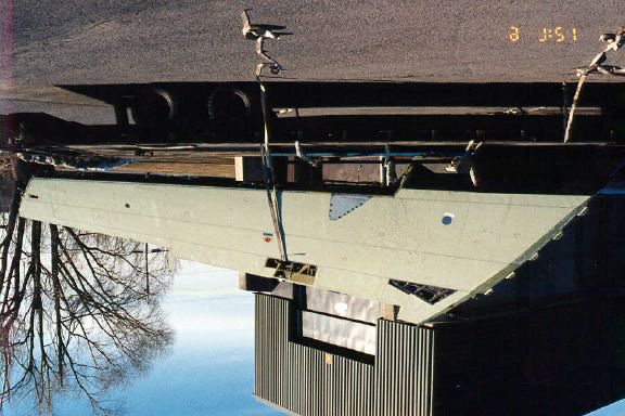
The rubber deicing boot on the leading edge of the JetStar wing was also
removed and the entire leading edge was polished (see Photo 2.9).
2.2 Wing Mounting Considerations
The second phase of the full-scale test site implementation study considered
mounting the acquired wing onto a platform. The ideal design of the
platform would: hold the wing at an ideal working height; facilitate
I:\Groups\CM1589\Reports\Wing\Final Version 1.0\Final Version 1.0 revised.doc
7 Final Version 1.0
January, 02
APS AVIATION INC. Last printed 3/28/02 2:17 PM2. WING TEST BED PREPARATION
movement (rotation); permit actuation of the wing panel during testing; and
allow for low-speed towing for short distance transportation. Several
companies, such as Lazer Inox, Max-Atlas, Chagnon Ltée, and NRC Canada
were approached in 1999 to tender quotations for the design and fabrication
of a wing dolly system.
The companies proposed similar dolly designs. In general, the dolly would
have consisted of two separate components; one to support the wing at the
wing root, and the second to support the wing at the wing tip. The dolly
assembly would fasten to existing attachment points at the wing root, while
requiring minor modifications to the wing tip in order to facilitate the
attachment of the dolly assembly at that end. The portion of the assembly
at the wing root would consist of two non-swivelling wheels. The portion
of the assembly at the wing tip would consist of one retractable swivelling
wheel, two retractable feet that could be extended for stability during
testing, and a towing eye. The dolly assembly would be designed so that
the working height of the top surface of the wing would be approximately
five feet above the ground.
The quotations received in 1999 for the design and fabrication of the wing
dolly assembly varied in price from CAN$13 600 to $20 000.
During the 1999-2000 test season, a new mounting system for the JetStar
wing was proposed. It consisted of an off-the-shelf 6.1 m (20 ft.)
galvanized scissor-lift pontoon boat trailer, with a weight capacity of
1 588 kg (3 500 lb.). The design of the trailer was examined in detail and
was found to address every one of the following test bed mounting system
requirements:
• The height of the trailer would allow the wing to be positioned at an ideal
working height approximately 1.5 m (5 ft.) above the ground;
• The swivelling wheel at the end of the trailer would facilitate movement
and allow the wing to be rotated during a test;
• The design of the trailer would not impede actuation of the various wing
surfaces during testing; and
• And the trailer was sufficiently stable to allow for low-speed towing for
short distance transportation.
More importantly, the purchase of the trailer represented a savings of more
than CAN$10 000 over the cheapest quotation received in 1999 for the
mounting of the wing. The boat trailer was purchased in January 2000 and
the wing was mounted upon it shortly thereafter. The wing was levelled
using various shims to reproduce the 2° dihedral and 1° angle of incidence
of the JetStar wing when attached to the fuselage. Photo 2.10 shows the
JetStar wing mounted on the boat trailer at the NRC Canada facility.
I:\Groups\CM1589\Reports\Wing\Final Version 1.0\Final Version 1.0 revised.doc
8 Final Version 1.0
January, 02
APS AVIATION INC. Last printed 3/28/02 2:17 PM2. WING TEST BED PREPARATION
2.3 Test Site Selection
The third and final phase of the full-scale test site implementation study
involved the examination and selection of a suitable full-scale test site. In
addressing these objectives, certain requirements, such as accessibility,
security, proximity to current APS installations, and containment and
recovery of sprayed fluids were examined. The centralized deicing facility at
Dorval Airport, operated by AéroMag 2000, was selected in 1999 because
it addressed every concern: the deicing facility is easily accessible, secure,
and located within one kilometre of the APS test site at Dorval Airport. It is
also equipped with a glycol recovery system. Furthermore, AéroMag deicing
vehicles and personnel could be used to spray de/anti-icing fluids during
wing tests. Outdoor tests using artificial precipitation sprayers could also be
performed at this facility. In return for the use of the facility, APS would
make the wing section available to AéroMag personnel for training purposes.
Alternative locations for outdoor testing include the exterior premises of
NRC Canada’s Climatic Engineering Facility in Ottawa and the exterior
premises of the ADGA hangar at Gatineau Airport.
NRC Canada’s Climatic Engineering Facility would be an ideal location for
any indoor tests in simulated precipitation. An alternative indoor site could
be the Institut de recherche d’Hydro-Québec (IREQ) climatic chamber in
Varennes.
2.4 Wing Transportation
Since the design of the wing mounting system does not conform to the
highway code, transportation companies were contacted to determine the
costs of transporting the wing dolly assembly from the NRC Canada facility
in Ottawa to the AéroMag deicing facility at Dorval Airport in Montreal by
means of a flatbed truck.
Several transport companies were contacted for quotations. The chosen
company, Goldie Mohr Limited of Barhaven, Ontario, operates flatbed trucks
with sliding ramps (see Photo 2.11), which are ideal for loading and
unloading equipment of this nature. The average transportation cost for a
one-way delivery between Montreal and Ottawa was CAN$700.
I:\Groups\CM1589\Reports\Wing\Final Version 1.0\Final Version 1.0 revised.doc
9 Final Version 1.0
January, 02
APS AVIATION INC. Last printed 3/28/02 2:17 PMThis page intentionally left blank.
I:\Groups\CM1589\Reports\Wing\Final Version 1.0\Final Version 1.0 revised.doc
10 Final Version 1.0
January, 02
APS AVIATION INC. Last printed 3/28/02 2:17 PM2. WING TEST BED PREPARATION
Photo 2.1
Lockheed JetStar
Photo 2.2
Truck and Trailer Used to Transport JetStar Wing
I:\Groups\CM1589\Reports\Wing\Photos\Chapter 2.doc
APS AVIATION INC. Printed: 3/28/02 2:24 PM
112. WING TEST BED PREPARATION
Photo 2.3
JetStar Wing upon Arrival in Ottawa
Photo 2.4
JetStar Wing Control Surfaces
I:\Groups\CM1589\Reports\Wing\Photos\Chapter 2.doc
APS AVIATION INC. Printed: 3/28/02 2:24 PM
132. WING TEST BED PREPARATION
Photo 2.5
Removal of the Wing from the Transportation Vehicle
Photo 2.6
Trailing Edge Quiet Area
I:\Groups\CM1589\Reports\Wing\Photos\Chapter 2.doc
APS AVIATION INC. Printed: 3/28/02 2:24 PM
152. WING TEST BED PREPARATION
Photo 2.7
Bracket Used to Secure Leading Edge Flap
Photo 2.8
Leading Edge Quiet Area
I:\Groups\CM1589\Reports\Wing\Photos\Chapter 2.doc
APS AVIATION INC. Printed: 3/28/02 2:24 PM
172. WING TEST BED PREPARATION
Photo 2.9
Polished Leading Edge of JetStar Wing
Photo 2.10
JetStar Wing on Boat Trailer
I:\Groups\CM1589\Reports\Wing\Photos\Chapter 2.doc
APS AVIATION INC. Printed: 3/28/02 2:24 PM
192. WING TEST BED PREPARATION
Photo 2.11
Flatbed Truck Moveable Ramp Used to Transport JetStar Wing and Wing
Mounting System
Photo 2.12
Wing and Trailer on Flatbed Truck at NRC Canada
I:\Groups\CM1589\Reports\Wing\Photos\Chapter 2.doc
APS AVIATION INC. Printed: 3/28/02 2:24 PM
213. LOCKHEED JETSTAR WING CHARACTERISTICS
3. LOCKHEED JETSTAR WING CHARACTERISTICS
3.1 Lockheed JetStar Wing Geometry
The following information pertains to the design characteristics of the
Lockheed JetStar wing:
• Wing section NACA 63A112 at the wing root;
• Wing section NACA 63A309 (modified) at the wing tip;
• Wing chord of 4.16 m at the wing root (13 ft. 7¾ in.);
• Wing chord of 1.55 m at the wing tip (5 ft. 1 in.);
• Incidence 1° at the wing root, -1° at the wing tip;
• Dihedral 2°;
• Sweepback 30° at quarter-chord;
• Conventional fail-safe stressed-skin structure of high-strength aluminum;
and
• Aluminum alloy aileron, double-slotted all-metal trailing edge flaps,
hinged leading edge slats, no spoilers.
Additional pertinent information on the design characteristics of the
Lockheed JetStar has been obtained from a Lockheed JetStar model
specification manual and from Jane’s 1967-68 Yearbook (see Appendix A).
During the 1999-2000 test season, APS personnel measured the precise
dimensions of the JetStar wing. Figure 3.1 shows a diagram of the
Lockheed JetStar wing including dimensions.
3.2 Lockheed JetStar Fuel System Design
The design of the fuel tank system of the Lockheed JetStar is displayed in
Figure 3.2. When intact, the entire system consists of four integral wing
tanks of approximately equal capacity (two tanks in each wing) and two
external tanks installed on the wings. The total fuel capacity of the six tanks
is approximately 10 070 L (5 790 L in the wing tanks and 4 280 L in the
external tanks).
The wing test bed consists of a starboard JetStar wing. The external fuel
tank (RH ext, see Figure 3.2) was removed by the salvage company and
was not delivered with the main wing section. Therefore, the fuel capacity
of the wing is restricted to the two integral wing tanks, main tanks no.3 and
no.4 (see Figure 3.2). The capacity of main tanks no.3 and no.4 are 1 476
and 1 420 L, respectively.
I:\Groups\CM1589\Reports\Wing\Final Version 1.0\Final Version 1.0 revised.doc
23 Final Version 1.0
January, 02
APS AVIATION INC. Last printed 3/28/02 2:17 PMFigure 3.1
JetStar Wing Dimensions
6'1"
1'10"
1.9m
23' 1" 0.6m
7.0m
5'31/2"
T1
1.6m 5'9"
1.8m 14'
T2 4.3m
11.5'
8'91/2"
2.7m 3.4m
5'51/4"
A1 1.7m
8'2"
2.5m
5'
LE2
1.5m LE1
8'1/2"
3'11" 1'2" 2.5m
1.2m 0.4m
27'7"
8.4m
cm1589/reports/wing/Wing Dimensions.DWG3. LOCKHEED JETSTAR WING CHARACTERISTICS
To obtain cold-soaking capabilities for future tests, the fuel tanks of the
JetStar wing would have to be filled with chilled liquid. If glycol is chosen, a
total of 3 185 kg would be required to fill the tanks to full capacity
(1 623 kg in main tank no.3 and 1 562 kg in main tank no.4).
3.3 Wing Quiet Areas
Wing quiet areas include aerodynamically quiet cavities. These control
surface-related cavities often cannot be observed during clean wing
configuration (with control surfaces retracted). The five quiet cavities on the
JetStar wing are found behind the two leading edge slats (LE1 and LE2), in
front of the two trailing edge flaps (T1 and T2), and in front of the aileron
(A1). The locations of these controls are shown in Figure 3.1.
3.4 Main Wing and Flight Control Surface Wing Gaps
Gaps refer to the tolerance spaces between the main wing structure and the
movable flight control surfaces. The gaps also correspond to the most likely
path that water/fluid would take when entering a quiet cavity.
Measurements for the JetStar wing were taken at 28 cm (11 in.) intervals
at the upper wing surface. Figure 3.3 shows the measurements.
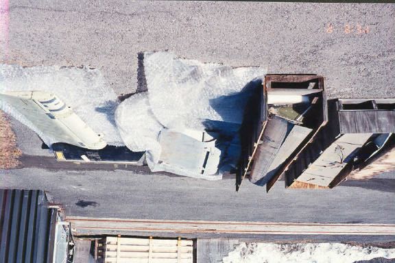
3.5 JetStar Wing Tests in Simulated Conditions
The NRC Canada Climatic Engineering Facility (CEF) in Ottawa was selected
as a suitable location for the conduct of indoor trials in simulated
precipitation using the JetStar wing. The CEF is partitioned into two
sections, separated by an insulated dividing door. Each partition can be
controlled separately, permitting different tests to be conducted
simultaneously. Photo 3.1 provides a general indication of the size of the
facility. Photos 3.2 and 3.3 provide interior images of the small and large
ends of the facility. The facility was designed and constructed for the
testing of locomotives. The size of the chamber is 31 m by 6 m and its
height is 8 m. The lowest temperature achievable is –46°C. Figure 3.4 is a
schematic of the JetStar wing in relation to the NRC Canada CEF cold
chamber in Ottawa.
I:\Groups\CM1589\Reports\Wing\Final Version 1.0\Final Version 1.0 revised.doc
26 Final Version 1.0
January, 02
APS AVIATION INC. Last printed 3/28/02 2:17 PMFigure 3.3
Hard Wing/Flight Surface Wing Gaps
x
TE1 x x 18
x 20
19
x x 21
x 23 22
x
TE2 x x 25 24
x 26
x 27
x 29 28
x
31
30
x x x
x x xx 17
x x x xx 12 1314 15 16
x 8 9 10 11
x x x x 5 6 7
2 3 4
1 LE2
LE1
Measurements taken at 28 cm intervals.
LE1 LE2 TE2 TE1
Gap Gap Gap Gap
Loc Loc Loc Loc
(mm) (mm) (mm) (mm)
1 1.75 14 0.72 18 0.97 25 1.75
2 2.24 15 < 0.38 19 0.89 26 < 0.38
3 1.75 16 1.19 20 1.19 27 < 0.38
4 1.75 17 0.61 21 2.29 28 0.89
5 2.29 22 1.75 29 0.61
6 1.19 23 1.19 30 < 0.38
7 1.75 24 < 0.38 31 < 0.38
8 0.61
9 1.19
10 1.75
11 1.75
12 1.75
13 0.61
cm1589/reports/wing//Wing Gaps.xls
Printed: 3/28/02, 2:27 PMFigure 3.4
JetStar Wing Inside NRC Canada Chamber
6.0 m
(20 ft)
31 m (103 ft)
cm1589/reports/wing/Wing inside Chamber (Version 2).DWG3. LOCKHEED JETSTAR WING CHARACTERISTICS
Photo 3.1
Outdoor View of NRC Canada Climatic Engineering Facility
Photo 3.2
Inside View of Small End of Climatic Engineering Facility
I:\GROUPS\CM1589\REPORTS\WING\PHOTOS\CHAPTER 3.DOC
March 28, 2002
293. LOCKHEED JETSTAR WING CHARACTERISTICS
Photo 3.3
Inside View of Large End of Climatic Engineering Facility
I:\GROUPS\CM1589\REPORTS\WING\PHOTOS\CHAPTER 3.DOC
March 28, 2002
314. FULL-SCALE TESTING WITH JETSTAR WING
4. FULL-SCALE TESTING WITH JETSTAR WING
During the 1999-2000 test season, full-scale testing with the JetStar wing was
conducted in natural and simulated precipitation conditions at NRC Canada in
Ottawa and at Dorval Airport in Montreal. Testing consisted of:
• Fluid application trials (Section 4.1);
• Testing of the Radiant Energy Corporation Deicing System (Section 4.2);
• Hot water deicing trials (Section 4.3);
• Use of ice detection sensors for end-of-runway application (Section 4.4); and
• Forced air trials (Section 4.5).
The purpose of this section is not to document the results of tests conducted
during the past year, but rather to display the full-scale test capabilities of the
JetStar wing. The results of Hot Water, Ice Detection Sensor, and Forced Air
trials with the JetStar wing are reported in detail in three associated reports,
TP 13663E, TP 13662E, and TP 13664E.
I:\Groups\CM1589\Reports\Wing\Final Version 1.0\Final Version 1.0 revised.doc
33 Final Version 1.0
January, 02
APS AVIATION INC. Last printed 3/28/02 2:17 PMThis page intentionally left blank.
344. FULL-SCALE TESTING WITH JETSTAR WING
4.1 Fluid Application Trials
Objective: Fluid application trials were conducted on behalf of a fluid
manufacturer to determine the behaviour, in particular the foaming and
wetting characteristics, of an aircraft deicing fluid on a wing when applied
using standard industry methods
Procedures: The JetStar test wing was set up outside of NRC Canada in
Ottawa and positioned over a tarp for fluid collection purposes (Photo 4.1).
The deicing fluid was heated in a hot water tank to 80°C and then applied
to the JetStar wing using a mobile fluid sprayer developed by APS on behalf
of Transport Canada (Photo 4.2).
Photo 4.1
JetStar Wing Test Set-up for Fluid Application Trials
Photo 4.2
Type I Fluid Application using Mobile Sprayer
I:\Groups\CM1589\Reports\Wing\Final Version 1.0\Final Version 1.0 revised.doc
35 Final Version 1.0
APS AVIATION INC. January, 02
Last printed 3/28/02 2:17 PMYou can also read