Turbo Systems Installation Instructions - Acura Integra / Honda Civic
←
→
Page content transcription
If your browser does not render page correctly, please read the page content below
Turbo Systems
   Installation Instructions

                          Acura Integra /
                           Honda Civic
Disclaimer: The product described herein are for off-road use only and are not intended for installation on emissions
                                                controlled vehicles.

              2255 Agate Court     Simi Valley, CA 93065 Tel. 805.581.0333         Fax: 805.584.1913
                                             www.turboneticsinc.com
                                                                                                       Part No. 60108-rev.b
Turbo Kit Installation Instructions No. 60108-rev.b

IMPORTANT, READ THIS FIRST: Study these instructions completely before proceeding.
Engine and/or turbocharger damage may occur if any component within these instructions
is improperly installed. Turbonetics, Inc. or any of its distributors cannot be held responsible for
damages as a result of negligent or improper installation. This complete turbocharger system can
be installed using common tools and automotive procedures, but installer must have a thorough
knowledge of automotive engine operation and feel comfortable working on the vehicle. If in
doubt, consult a knowledgeable turbo installer or Turbonetics tech support specialist with any
questions.

Although this turbo system has been designed to use existing emissions controls (including
catalytic converter), check local laws regarding aftermarket modification to emission controlled
vehicles. Remove the turbocharger kit from its carton and inspect for any obvious physical
damage. All kit components are thoroughly inspected and carefully packaged prior to shipment
from the factory. If any shipping damage is evident, contact your supplier and request that they
process a claim with the shipper involved. Be sure to review the Turbo System Parts List to verify
that you have all necessary kit components to proceed. If any components in the parts list are
missing, contact Turbonetics, Inc. Customer Service department.

Before proceeding, it is recommended to have the following items:
• Honda / Acura service / repair manual
• A large table / bench nearby
• Standard selection of automotive tools
• Plenty of adjacent available workspace
• The ability to lift the vehicle (at least a foot or two off the ground)
• Replacement oil pan gasket or RTV sealant, oil filter and engine coolant
• NPT thread sealant tape

Removing the Factory Exhaust Manifold and Downpipe
Begin by removing the following:
        1.) Exhaust manifold and A-pipe to the catalytic converter. Save the hardware used to
            mount the manifold to the head and the hardware that mount the A-pipe to the
            catalytic converter.
                 a. Remove the oxygen sensor from the exhaust manifold, using great care not
                     to damage it.
                 b. Remove the exhaust donut gasket found at the end of the factory A-pipe.
        2.) Air box and intake pipe. Completely remove the intake system from the throttle body
            all the way to the box located in the fender well.
        3.) Remove the bumper cover to expose the area under the bumper.
        4.) Remove the plastic skirt located directly under the engine and attached to the
            bumper cover.

**Tip: Keep an empty box on hand to keep the hardware removed. Some of these will be reused
when installing the turbo kit.

Once the exhaust manifold has been removed, locate the air conditioning compressor line. Take
note of all of the brackets that maintain a fixed position for this line. Removing these brackets will
make it free from constraint and allow you to pull it back to have more room when installing the
turbo and manifold. You can use cable / zip ties to keep the a/c lines secured.

            2255 Agate Court     Simi Valley, CA 93065 Tel. 805.581.0333   Fax: 805.584.1913
                                            www.turboneticsinc.com
                                                                                                         2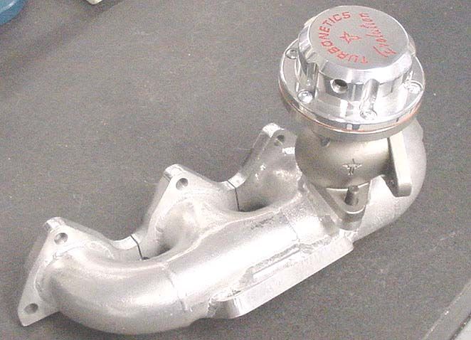
Mounting the Turbocharger to the Manifold and Downpipe
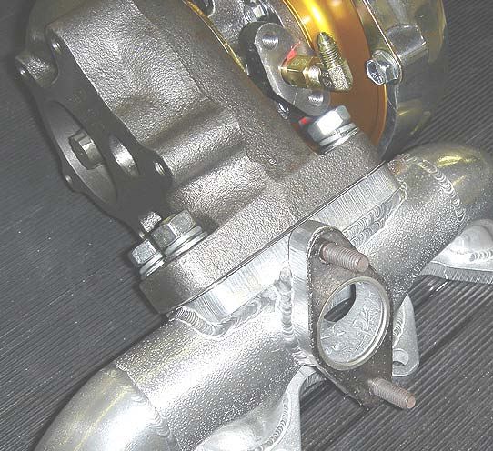
Orientating the Turbocharger
The arrows in figure 1 and 2 point to the areas of a turbocharger which keep the center section in
a fixed position.
1.) Loosen the bolts until the compressor housing, bearing housing, and turbine housing
will rotate freely in relation to one another.
2.) Attach the turbo to the manifold with the supplied hardware and gasket as shown in
figure 3 and mount the assembly onto the head using the factory gasket. You will
find on some applications that it is easier to drop the turbo in first, then bolt on the
manifold, then bolt the turbo to the manifold.
3.) Rotate the center section of the turbocharger so that the oil drain is facing
downwards. Keep in mind that the oil drain is a gravity drain system, and the drain
fitting should be pointed as near to vertical as possible. If this is not done, the oil will
not drain out of the turbocharger properly, and it may blow oil past the seals.
4.) Rotate the polished compressor housing so that the discharge is pointed down to
where the intercooler piping will be mounted.
5.) Tighten the turbine housing and compressor housing bolts
Turbine Housing
Turbine Housing Clamps
Turbine Housing Bolts
Figure 1
Compressor Housing Clamps
Compressor Housing
Compressor Housing Bolts
Figure 2
2255 Agate Court Simi Valley, CA 93065 Tel. 805.581.0333 Fax: 805.584.1913
www.turboneticsinc.com
3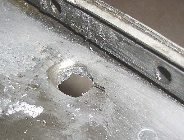
Mounting the Turbocharger to the Manifold

   1.) Thread the four supplied M10x1.25 – 42mm long studs into the threaded holes on the
       turbo mounting flanges of the manifold (as shown in figure 3)
   2.) With the manifold facing upwards (pointed side of the exhaust manifold flange facing
       upwards) install the turbo to the manifold with the compressor housing facing toward the
       left hand side (passenger side) (as shown in figure 4)
   3.) Tighten the turbo to the manifold using the supplied nuts and washers

                       Figure 3                                           Figure 4

Mounting the Wastegate to the Manifold

   1.) Thread the two supplied M8x1.25 – 30mm long stud into the threaded holes on the
       wastegate mounting flange of the manifold (as shown in figure 5)
   2.) With the manifold facing upwards (pointed side of the exhaust manifold flange facing
       upwards) install the wastegate to the manifold with the wastegate discharge flange facing
       toward the right hand side (driver’s side) (as shown in figure 6)
   3.) Tighten the wastegate to the manifold using the supplied nuts and washers

                       Figure 5                                                Figure 6

         2255 Agate Court   Simi Valley, CA 93065 Tel. 805.581.0333   Fax: 805.584.1913
                                       www.turboneticsinc.com
                                                                                                   4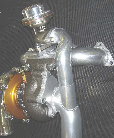
Installing the Downpipe

    1.) Install the factory donut gasket onto the end of the downpipe.
    2.) With the turbo / manifold combination in place, install the downpipe onto the turbine
        housing using the provided hardware and to the catalytic converter using the factory
        hardware.
    3.) Install the wastegate dump tube into the open port on the downpipe, rotating it as you
        press it in if necessary (the fitment should be snug).

    **Tip: You may want to keep all of the fasteners loosely installed until all of the components
    are in place. This will make installing all of the components easier. Tighten all of the
    hardware only after everything is in place.

When mounting the turbo to the manifold and mounting the downpipe onto the turbo, use a thin
layer of high-temperature gray silicone, or Permatex Copper Coat as a sealant. Though all
flanges are well-machined, flat surfaces, the silicone will further cover any exhaust leaks that may
slip by.

                                                  Figure 7

           2255 Agate Court   Simi Valley, CA 93065 Tel. 805.581.0333    Fax: 805.584.1913
                                         www.turboneticsinc.com
                                                                                                       5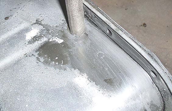
Oil Feed and Return

Installing the Oil Feed Line

Oil pressure for the turbo is acquired from the oil pressure sending unit. This unit is located near
the oil filter (with the D16, it is located above the oil filter). Remove this unit and install the brass
tee fitting with the –3 straight fitting and the oil pressure sending unit as shown in figure 9 and 10.
Once this is done, install the braided oil feed line onto the tapered –3 fitting. The line needs to be
routed around the distributor side of the engine and pass under the distributor on its way to the
turbo, where it should be fastened to the 90 degree –3 fitting installed on the top of the
turbocharger bearing housing (see figure. 8).

                            Figure 8                                                  Figure 9

                                                           Figure 10

Tapping the Oil Pan

Oil drainage from the turbocharger relies on gravity, making this part of the turbo kit installation
very critical. Failing to install the oil drain system properly could cause the oil to not drain from
the turbocharger properly, which can result in oil blowing past the seals of the turbo. This would
cause oil to be pumped into the exhaust and/or into the intercooler and engine.

           2255 Agate Court    Simi Valley, CA 93065 Tel. 805.581.0333       Fax: 805.584.1913
                                          www.turboneticsinc.com
                                                                                                            6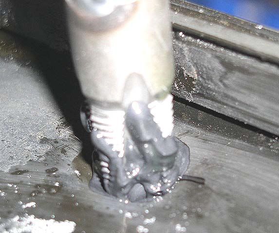
The provided brass _ NPT x 5/8” hose fitting needs to be threaded into the oil pan for the oil
return line. It is important to mount this fitting as high as possible on the pan without having the
fitting interfere with the oil pan mounting flange/bolts. The mounting point should provide a
smooth, downward sloping path for the oil return hose to attach to from the turbo oil drain. The
pan needs to have a hole punched in it, and the hole threaded using the provided tap. After
choosing a suitable location for installing the fitting, punch a hole in the pan using progressively
larger hole punches until the hole is about 9/16” in diameter as shown in figure 11 to 13. The
metal that is now curved inwards from creating the hole will provide the surface to be tapped
using the provided pipe tap. Tap the hole using this pipe tap, but make sure it is packed with
heavy grease in order to catch the shavings created during the tapping process. (shown in figure
14) This will keep the shavings from getting in the oil. After this is completed, thread in the brass
fitting, using a thread sealant to prevent oil leakage. (as shown in figure 16) Now attach the
provided oil drain hose, cutting it to length as needed and using the provided hose clamps to
secure the hose. It is very important that the routing of the oil drain hose be smooth, with no
kinks or bends. Also, the hose should never be routed in a way that would cause the oil to have
to travel “uphill”.

                         Figure 11                                                 Figure 12

                         Figure 13                                                     Figure 14

           2255 Agate Court   Simi Valley, CA 93065 Tel. 805.581.0333     Fax: 805.584.1913
                                         www.turboneticsinc.com
                                                                                                        7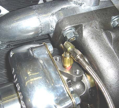
Figure 15                                                        Figure 16

Fuel and Ignition Management wiring

Installing the FIC

Remove the distributor and find the positive (+) and negative (-) terminals exposed.

The positive side of the coil makes for an excellent key-on 12V source. If this isn’t powered, the
car will not run, and neither will your fuel and ignition components.

Never use the negative side of the coil as a ground, as it is not a constant ground.

For a secure ground, use the negative (-) terminal of the car battery.

                                                                                       Diagram 1

MF2 - All wires connections must be soldered for proper running conditions.
             • Black                    Ground (-), battery
             • White 1                  Ground (-), battery
             • White 2                  MAP sensor
             • Red 1                    12V (+), key-on
             • Red 2                    Fuel injector harness
             • Brown                    Fuel injector harness
             • Yellow                   Negative (-), coil
             • Orange                   MAP sensor
             • Blue                     MAP sensor

           2255 Agate Court   Simi Valley, CA 93065 Tel. 805.581.0333    Fax: 805.584.1913
                                         www.turboneticsinc.com
                                                                                                     8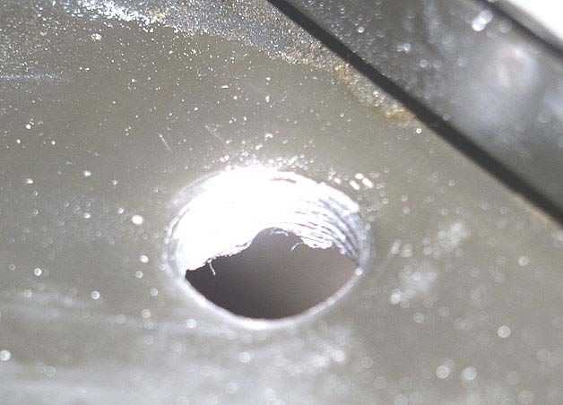
**Note 1: Both red wires are interchangeable. Either one can be used for 12V (+), key-
        on or to the fuel injector harness.

        **Note 2: Both white wires are interchangeable. Either one can be used for ground (-),
        battery or MAP sensor.

When mounting the MF2, find a suitable location that minimizes vibration and exposure to heat
and moisture.

If you are using an ignition amplifier, do not connect the MF2 power signal to the coil (+) or (-).
The MF2 uses 12V, and the 300-400 volts from an amplifier will destroy the MF2. Find an
alternate RPM signal.

Installing the MSD BTM

The following ignition instructions are for the MSD BTM. Should you use a 6A in conjunction with
this, follow the included instructions.

MSD
             •   Red                       Positive (+), coil
             •   Black                     Ground (-), battery
             •   White                     Negative (-), coil
             •   Orange                    Negative (-), coil

                                                   Diagram 2

           2255 Agate Court   Simi Valley, CA 93065 Tel. 805.581.0333     Fax: 805.584.1913
                                         www.turboneticsinc.com
                                                                                                      9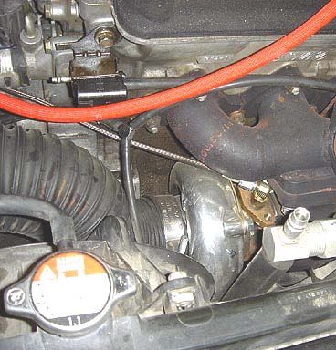
Installing the Missing Link

The MAP sensor is generally located on top of the throttle body held by 2 screws. Remove the
MAP sensor and install the provided Missing Link in its place using the provided o-ring. Re-install
the MAP sensor onto the missing link using the provided o-ring and hardware. Make sure that
the o-rings are installed properly. Any leaks in this system would cause severe drivability
problems, as well as tripping the check engine light. (see figures 17-21)

Should a check engine light come on, turn off the car, clear the ECU by disconnecting the battery
and start again. If the check engine light still comes on, double check the MAP sensor
installation.

                      Figure 17                                                  Figure 18

                      Figure 19                                                Figure 20

          2255 Agate Court   Simi Valley, CA 93065 Tel. 805.581.0333    Fax: 805.584.1913
                                        www.turboneticsinc.com
                                                                                                    10
Figure 21
Installing Additional Fuel Injectors
Preparing your Honda / Acura fuel system for the additional injectors is limited to these simple
steps:
1.) Strip away the spongy cover of the factory fuel line that transitions from the fuel filter
to the fuel rail. This is NOT the fuel line from the fuel pressure regulator.
2.) Cut the fuel line cleanly in half. (as shown in figure 22)
3.) Take the brass 4-way tee supplied and apply Teflon tape or liquid Teflon to all the
threads, careful not to leave any dirt or debris in the tee, and then reassemble. Two
of the tee’s barbs intercept the factory fuel line that you have just cut.
4.) Attach the two fuel lines that will be connected to the fuel injectors.
5.) Take the two fuel injectors supplied with the kit and mount them on to the intercooler
pipe with the threaded bosses. Keep the electrical terminals accessible to the
electrical connectors.
Factory Fuel Filter
Factory Fuel Line
Figure 22
2255 Agate Court Simi Valley, CA 93065 Tel. 805.581.0333 Fax: 805.584.1913
www.turboneticsinc.com
11Installing Intercooler/Piping
Mounting the Intercooler
Begin by removing the driver’s and passenger’s side tow hooks.
With the front fascia of the car exposed, you now have access to the installation points for the
intercooler. Take the intercooler for your specific application and position it directly in the center
of the front fascia, and the mounting points should become obvious. Mount the intercooler using
the hardware provided. (See figure 23 to 25)
Figure 23 Figure 24
Figure 25
2255 Agate Court Simi Valley, CA 93065 Tel. 805.581.0333 Fax: 805.584.1913
www.turboneticsinc.com
12Installing Intercooler Piping
With the intercooler mounted in place, slip the hose connectors onto the end tank tubes and
attach the intercooler pipes as show in figure 26 to 29. To ease the installation of the intercooler
pipe couplers, you can apply soapy water to the inside of the couplers to make them easier to slip
them into place.
Figure 26 Figure 27
Figure 28
Figure 29
Once the intercooler pipe to the throttle body is installed (as shown figure 29):
1.) With the fuel injectors mounted in place, slip the fuel line over the machined inlet of
the fuel injectors and install provided hose clamps.
With everything in place, the bumper cover installation may require that the bumper cover be
trimmed as needed to accommodate the intercooler.
2255 Agate Court Simi Valley, CA 93065 Tel. 805.581.0333 Fax: 805.584.1913
www.turboneticsinc.com
13Air Intake / Filter
Install the provided intake flex hose onto the inlet end of the turbo as shown in figure 30. Route
the flex hose and attach the filter adapter and air filter as shown in figure 31. Next, attach the
provided 3/8” rubber hose from the air filter adapter to the valve cover breather port.
Figure 31
Figure 30
Figure 32
2255 Agate Court Simi Valley, CA 93065 Tel. 805.581.0333 Fax: 805.584.1913
www.turboneticsinc.com
14Vacuum Routing
Wastegate
Both the wastegate and turbocharger compressor housing require that you install the provided
brass vacuum fittings as shown in figure 33. For the wastegate boost source, connect the brass
fitting on the compressor housing and the fitting on the side of the wastegate with the vacuum
hose supplied. (See figure 34)
See diagram 3 for vacuum hose routing
Figure 33
Figure 34
Diagram 3
2255 Agate Court Simi Valley, CA 93065 Tel. 805.581.0333 Fax: 805.584.1913
www.turboneticsinc.com
15Blow off Valve
1.) Install the o-ring seal in the pocket on top of the weld tube, using a small amount of
silicone grease to keep it in place during assembly
2.) Rotate the mounting flange to your desired position, and tighten the Raptor blow off valve
using the supplied hex bolts as shown in diagram 5
3.) Refer to the sensing line schematic shown in diagram 4. Connect the vacuum sensing
line using the supplied 1/8” silicone vacuum hose
• The vacuum sensing line (top port) may be connected to any convenient intake manifold
pressure source (suggested connection location is on the intake manifold plenum, since
runner locations may cause pulsing, which may affect control stability)
• The boost sensing line (bottom port) may be connected to any convenient source
between the turbocharger compressor discharge and throttle plate (location isn’t critical).
Since most of the valve motion in controlled by intake manifold vacuum, the valve will
operate without this sensing line, but will have quicker response with it connected.
IMPORTANT: Do not plug this hole, it needs to be able to breath
Diagram 4
Diagram 5
2255 Agate Court Simi Valley, CA 93065 Tel. 805.581.0333 Fax: 805.584.1913
www.turboneticsinc.com
16Starting the Vehicle
1.) Double check that all connections are correct, and that all bolts and studs have been
fastened, as well as all intercooler pipes couplers.
2.) Before starting up the car, make sure that all electrical connections are correct.
3.) Verify proper oil feed by disconnecting all of the spark plug wires from the spark plugs
and take the oil feed line that connects to the turbocharger and place the end into a cup.
Turn the car over to verify that oil passes through the line. After verifying oil flow, re-
attach the line to the turbo.
4.) Check the oil and coolant level.
5.) Spark plugs should be gapped between 035” and 038”. Begin at 035” and should misfire
occur, drop the gap down to 028”.
6.) Verify that the gasoline in the tank is a minimum of 91 octane.
7.) Verify that the ignition timing is set to factory recommendations.
8.) Start the car; allow 5-10 minutes to warm up. After operating temperature has been
achieved, proceed to test drive the car. If the check engine light comes on, double
check that the map sensor Missing Link has been installed properly. Disconnect the
negative terminal of the battery and test drive it again.
9.) Stop after initial test drive and check for oil leaks. Once cooled down, double check all
nuts, bolts, fittings, and harnesses.
10.) To verify that the fuel controller is working, open the MF2 box and make sure that the
threshold light is coming on at 1-3psi of boost, and that the green light is also on.
11.) To verify that the MSD is operational: As you are driving under boost, turn the knob
towards retard beyond recommended settings and if you notice a loss of power, it is
working.
2255 Agate Court Simi Valley, CA 93065 Tel. 805.581.0333 Fax: 805.584.1913
www.turboneticsinc.com
17You can also read