UF3300 - Micronics Flow Meters
←
→
Page content transcription
If your browser does not render page correctly, please read the page content below
UF3300
UF3300FM: Wall-Mounted Ultrasonic Flow Meter
UF3300HM: Wall-Mounted Ultrasonic Heat Meter

 User Manual

 Micronics Ltd, Knaves Beech Business Centre,
 Davies Way, Loudwater, High Wycombe, Bucks HP10 9QR

 Telephone: +44(0)1628 810456 E-mail: sales@micronicsltd.co.uk
 www.micronicsflowmeters.com

 Issue 1.0
Micronics UF3300 User Manual

CONTENTS

1 INTRODUCTION ................................................................................................................................................... 1
 1.1 General Description ............................................................................................................ 1
 1.2 How Does It Work? ............................................................................................................. 2
 1.2.1 Reflex (V) Mode........................................................................................................... 4
 1.2.2 Double Reflex (W) Mode ............................................................................................. 4
 1.2.3 Triple Reflex (WV) Mode ............................................................................................. 4
 1.2.4 Quadruple Reflex (WW) Mode ..................................................................................... 4
 1.2.5 Diagonal Mode ............................................................................................................ 4
 1.3 Package Contents .............................................................................................................. 5
 1.4 Display and Connectors ...................................................................................................... 6
 1.5 Keypad ............................................................................................................................... 8
 1.5.1 Dual Function Numerical Keypad................................................................................. 8
 1.5.2 Menus and the Menu Selection Keys ........................................................................... 9

2 INSTALLATION.................................................................................................................................................... 11
 2.1 Positioning ........................................................................................................................ 11
 2.2 Mounting........................................................................................................................... 11
 2.3 Connections...................................................................................................................... 12
 2.3.1 Power Supply ............................................................................................................ 12
 2.3.2 Control & monitoring cables ....................................................................................... 13
 2.3.3 USB Connector.......................................................................................................... 14
 2.4 Positioning the Transducers ............................................................................................. 15
 2.5 Attaching the Transducers ................................................................................................ 16
 2.5.1 Cleaning the Contact Area ......................................................................................... 16
 2.5.2 Attaching the Guide Rail to the Pipe .......................................................................... 16
 2.5.3 Fitting the Transducers .............................................................................................. 17
 2.5.4 Fixing Transducers in Diagonal Mode ........................................................................ 20
 2.6 Connecting Temperature Probes (UF3300 HM Models Only) ........................................... 22
 2.7 Calibrate the PT100 Sensors (Heat Meter versions only).................................................. 23
 2.8 Attach the PT100 Sensors (Heat Meter versions only) ...................................................... 23
 2.9 Switching on for the First Time.......................................................................................... 24
 2.9.1 Checking System Health ........................................................................................... 24
 2.9.2 Selecting a Language ................................................................................................ 24
 2.9.3 Setting the Date & Time ............................................................................................. 25
 2.9.4 Enabling/Disabling the Backlight ................................................................................ 25
 2.9.5 Enabling/Disabling Audible Keypress ........................................................................ 26

3 USING THE QUICK START MENU .................................................................................................................... 27
 3.1 Entering the Site Data....................................................................................................... 27
 3.2 Attaching and Connecting the Flow Sensors..................................................................... 29
 3.3 Taking a Flow Reading ..................................................................................................... 29
 3.4 Flow / Energy / Velocity Monitoring ................................................................................... 30
 3.5 Total Flows ....................................................................................................................... 30
 3.5.1 Calculating the Average Flow or Power ..................................................................... 31

Page i Issue 1.0 April 2021
Micronics UF3300 User Manual

 3.5.2 Resetting Totals......................................................................................................... 31

4 MANAGING NAMED SITES ............................................................................................................................... 32
 4.1 View/Edit Site Data ........................................................................................................... 32
 4.2 Selecting an Existing Site ................................................................................................. 33
 4.3 Adding a New Site ............................................................................................................ 34
 4.4 Changing a Site Name ...................................................................................................... 34
 4.5 Editing Site Data ............................................................................................................... 35
 4.6 Changing Calibration Parameters ..................................................................................... 36
 4.6.1 Adjusting the Zero Cutoff ........................................................................................... 36
 4.6.2 Adjusting the Zero-Flow Offset (ZFO) ........................................................................ 36
 4.6.3 Adjusting the Calibration Factor ................................................................................. 37
 4.6.4 Adjusting the Roughness Factor ................................................................................ 39
 4.6.5 Adjusting the Damping Factor .................................................................................... 40

5 LOGGING FUNCTIONS ....................................................................................................................................... 41
 5.1 Manual Logging ................................................................................................................ 41
 5.2 Scheduling Logging .......................................................................................................... 41
 5.3 Stopping Logging .............................................................................................................. 42
 5.4 Copying Logged Data to a USB Memory Stick.................................................................. 42
 5.5 Clearing Log Files ............................................................................................................. 43
 5.6 Logger Status ................................................................................................................... 43

6 OUTPUTS .......................................................................................................................................................... 44
 6.1 Current Loop Setup .......................................................................................................... 44
 6.1.1 Example .................................................................................................................... 45
 6.1.2 Converting the Measured Current to Flow Rate ......................................................... 46
 6.2 Digital Outputs .................................................................................................................. 47
 6.2.1 Pulse Output .............................................................................................................. 48
 6.2.2 Alarm Output ............................................................................................................. 51
 6.2.3 Frequency Output ...................................................................................................... 53

7 HEAT METER ..................................................................................................................................................... 54
 7.1 Calibrate Temperature Sensors ........................................................................................ 54

8 PRIMARY FLOW ................................................................................................................................................ 55

9 MAINTENANCE AND REPAIR ........................................................................................................................... 56

10 TROUBLESHOOTING......................................................................................................................................... 57
 10.1 Overview .......................................................................................................................... 57
 10.2 General Troubleshooting Procedure ................................................................................. 58
 10.3 Warning and Status Messages ......................................................................................... 59
 10.3.1 Flow Rate Errors & Messages ................................................................................... 59
 10.3.2 Heat Meter Errors & Messages .................................................................................. 60
 10.3.3 Current Loop and Digital Output Errors & Messages ................................................. 60

Issue 1.0 April 2021 Page ii
Micronics UF3300 User Manual

 10.3.4 Data Logging Errors & Messages .............................................................................. 61
 10.3.5 Set-up and Other Errors & Messages ........................................................................ 63
 10.4 Diagnostics ....................................................................................................................... 65
 10.4.1 Advanced Diagnostics ............................................................................................... 66

11 APPENDIX ......................................................................................................................................................... 67
 11.1 Specification ..................................................................................................................... 67
 11.2 Declaration of Conformity ................................................................................................. 70

Page iii Issue 1.0 April 2021
Micronics UF3300 User Manual

1 INTRODUCTION

1.1 General Description
The UF3300 is a wall-mounted flow meter (and heat meter depending on configuration options) that
uses clamp-on transducers to enable the flow of a liquid within a closed pipe to be measured
accurately without needing to insert any mechanical parts through the pipe wall or protrude into the
flow system.
Using ultrasonic transit time techniques, the UF3300 is controlled by a micro-processor system
which contains a wide range of data that enables it to be used with pipes with an outside diameter
ranging from 13mm up to 2000mm (depending on configuration) and constructed of a wide range of
materials. The instrument will also operate over a wide range of fluid temperatures.
The UF3300 has the following standard features:
• Large, easy to read graphic display with backlighting.
• Simple to follow dual function keypad.
• Easy to follow ‘Quick Start’ set up procedure.
• Continuous signal monitoring.
• Three isolated switched outputs for use in any combination as a:
 o Pulse output (on volume or 1energy),
 o Frequency output (on flow or 1power), or
 o Alarm output (on flow, volume, 1power, 1energy, flow signal).
• Current output with a selectable range between 0 and 24mA including support for an alarm
 current.
• Diagnostics.
Volumetric flow rates are displayed in l/s, l/min, l/h, m³/s, m³/min, m³/h, Ml/s, Ml/min, Ml/hr, Ml/day,
USgals/sec, USgals/min, USgals/h, USgals/day, Barrel/h, Barrel/day, ft3/sec, ft3/min, ft3/hr,
MUSgal/hr), MUSgal/day, Imp Gals/sec, Imp. Gal/m, Imp Gals/hr, Imp Gals/day, Barrels/hr,
Barrels/day. Linear velocity is displayed in metres or feet per second. When operating in the ‘Flow
Reading’ mode, the total volumes, both positive and negative, are displayed up to a maximum 12-
digit number.
The flowmeter can be used to measure clean liquids that have less than 3% by volume of
particulate content. Cloudy liquids such as river water and effluent can be measured along with
cleaner liquids such as demineralised water.

1 On models with a heat-meter

Issue 1.0 April 2021 Page 1
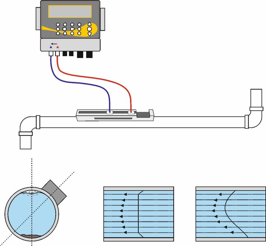
Micronics UF3300 User Manual

Typical applications:
• River water
• Seawater
• Potable water
• Demineralised water
• Treated water

1.2 How Does It Work?
The UF3300 flow meter uses a cross correlation transit time algorithm to provide accurate flow
measurements.
An ultrasonic beam of a given frequency is generated by applying a repetitive voltage pulse to the
transducer crystals. This transmission goes first from the downstream transducer to the upstream
transducer as shown in the upper half of Figure 1. The transmission is then made in the reverse
direction, being sent from the upstream transducer to the downstream transducer as shown in the
lower half of Figure 1. The speed at which the ultrasound is transmitted through the liquid is
accelerated or decelerated slightly by the velocity of the liquid through the pipe. The subsequent
time difference T1 – T2 is directly proportional to the liquid flow velocity.

Figure 1 Principle of operation

The UF3300 system can be set up to operate in one of five modes determined mainly by the pipe
diameter and the type of transducer set in use. Figure 2 illustrates the importance of applying the
correct separation distance between the transducers to obtain the strongest signal.

Page 2 Issue 1.0 April 2021
Micronics UF3300 User Manual

 Reflex (V) Mode
 (single bounce)

 Reflex (W) Mode
 (double bounce)

 Reflex (WV) Mode
 (triple bounce)

 Reflex (WW) Mode
 (quadruple bounce)

 Diagonal Mode

Figure 2 Operating modes

Issue 1.0 April 2021 Page 3
Micronics UF3300 User Manual

1.2.1 Reflex (V) Mode
This is the mode most commonly used. The two transducers (U & D) are attached to the pipe in line
with each other and the signals passing between them are reflected by the opposite pipe wall.
The separation distance is calculated by the instrument in response to entered data concerning the
pipe and fluid characteristics.

1.2.2 Double Reflex (W) Mode
In this mode the separation distance is calculated to give a double bounce2. This is most likely to
occur if the pipe diameter is small and the calculated reflex mode separation distance would be
impractical for the transducers in use.

1.2.3 Triple Reflex (WV) Mode
This mode goes one step further to detect a triple bounce2. This would normally be used when
working with very small pipes relative to the transducer in use.

1.2.4 Quadruple Reflex (WW) Mode
This mode goes one step further again, to use a quadruple bounce2. Again, this would normally be
used when working with very small pipes relative to the transducer in use.

1.2.5 Diagonal Mode
This mode might be selected by the instrument where relatively large pipes are concerned. In this
mode the transducers are located on opposite sides of the pipe, but the separation distance is still
critical in order for the signals to be received correctly.
This mode might be used with the standard ‘A’ & ‘B’ transducer sets but for very large pipes
installation the optional transducer set ‘D’ might be recommended.

2
 In general, it should be noted that errors accumulate as the number of bounces increase. Units are
calibrated using single reflex mode. Any inherent inaccuracy will be amplified by using higher order
modes such as triple and quadruple bounce. In addition to this, as the path length is longer, the
signal will also be more attenuated with higher order operating modes. Attenuation is also greater
with sensors using higher operating frequencies. (E.g. Signals from A sensors will be more
attenuated than with B sensors.)

Page 4 Issue 1.0 April 2021
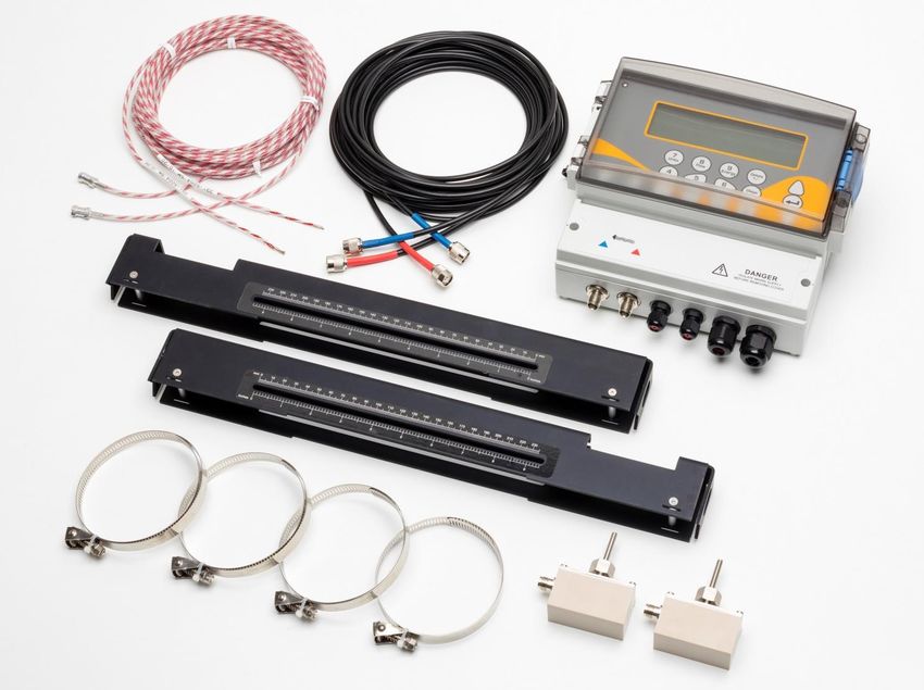
Micronics UF3300 User Manual

1.3 Package Contents
The unit consists of the following components:
1. UF3300 electronics unit
 Incorporating keypad and backlit display.
2. Transducer cables x 2, (2m)
3. Guide rail (optional second rail for diagonal configuration)
 For use with A or B type transducers
4. Stainless steel bands x 4 (larger sizes available)
5. Transducer set 'B' : for use on pipes 50mm to 2000mm outside diameter, or
 Transducers set 'A': for use on pipes 13mm to 115mm outside diameter.
Supplied with heat meter versions only:
6. RTD PT100 temperature sensors with clamps (not shown)
The package also contains two syringes with ultrasonic couplant for standard and high temperature
applications, and a copy of this manual (not shown).

 1

 2
 6

 3

 4

 5

Figure 3 Package Contents

Issue 1.0 April 2021 Page 5
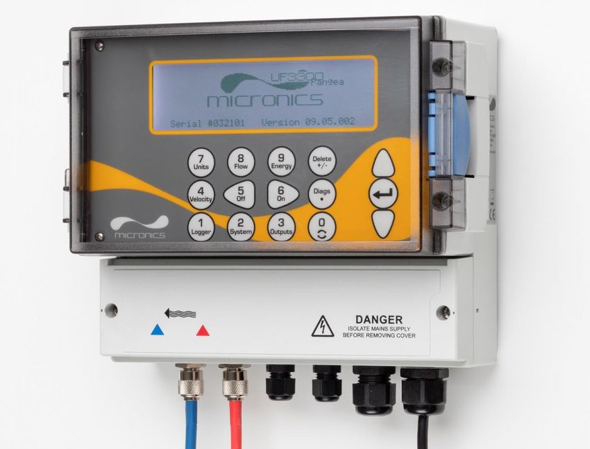
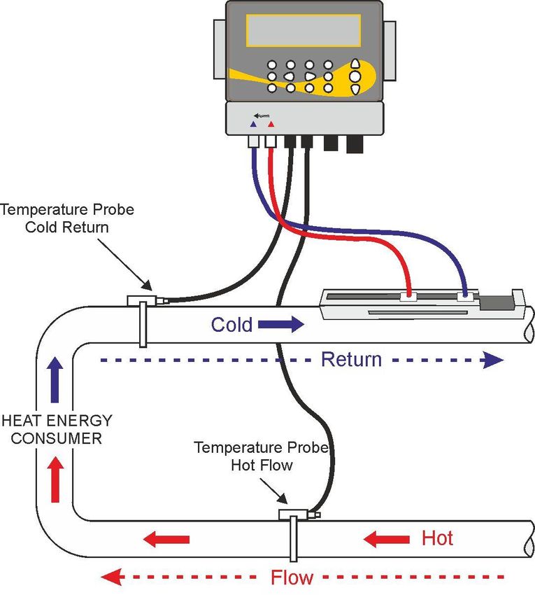
Micronics UF3300 User Manual

1.4 Display and Connectors
The UF3300 unit is microprocessor-controlled, operated through a menu system using an inbuilt
LCD display and keypad. It can display the instantaneous fluid flow rate or velocity, together with
totalised values.
The instrument can also provide a variable current or variable ‘pulse’ (volumetric, energy, or flow
frequency) output that is proportional to the detected flow rate. In addition to this, the instrument can
also be used to signal alarm conditions such as flow too high, too low or a volume being exceeded.
This output can be calibrated to suit a particular flow range and used with a range of external
interface devices, such as those found in BMS or site monitoring systems. The three isolated
outputs provided can be configured as required in any order and with any functionality as just
mentioned.
Heat meter versions of the UF3300 can be used to measure energy and power. They are supplied
with RTD probes which, when properly placed, can be used to calculate energy lost or absorbed in
a heater or chiller circuit. It does this by measuring the difference in temperature between the
probes, which are usually placed on the flow and return pipes at the point of source. The unit is
calibrated for ordinary water but is also capable of making an estimate when the system contains a
proportion of glycol3.
Obviously, since this method of energy calculation relies on measuring the temperature on the
outside of the pipe, the assumption made is that the temperature drop between the fluid and the
outside wall is the same at both measurement points. With careful selection of measurement points
on pipes whose wall and lining are good thermal conductors, a reasonable degree of accuracy in
the measurement of the temperature differential is possible, however with pipe materials that are
poor thermal conductors (e.g. plastic, epoxy etc.) it is recommended that PT100 pocket sensors be
used instead. With the careful choice of sensor type and installation method, it may be possible to
install these sensors without having to interrupt flow.

3 The proportions of water glycol are selected when choosing Fluid Type. The assumption is that the type of
glycol is ethylene (C2H6O2) with a Specific Heat Capacity (SHC) of 3.77kJ/kg⁰K, and a Relative Density (RD)
of 1.05 @25⁰C.
It has also been found that the SHC of ethylene glycol-based additives varies significantly by brand. For this
reason, and because the exact proportion and type of glycol being used are often not known, the energy
values obtained when using a glycol/water mix should be considered at best, only an estimate.
The SHC and RD for other fluid types should also be considered approximate. Published data for these other
fluids often varies significantly and is dependent on many factors that are outside the scope of this instrument
to compensate for.

Page 6 Issue 1.0 April 2021
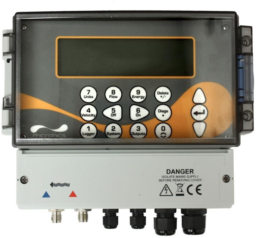
Micronics UF3300 User Manual

UF3300 units can also act as a data logger (requires data logger option). When operating in the
data logger mode, data is saved to non-volatile internal storage. This data may be downloaded at a
later date via a flash drive inserted in the USB socket. Data is saved as text in a CSV file which may
then be loaded directly into a program such as Microsoft™ Excel™. The internal storage capacity is
8GB.

 LCD display
 Cover latch

 Keypad

 Terminal block cover

 Note: USB
 socket on left
 side

 Transducer cable RTD PT100/ Power cable
 connectors output cable glands
 glands

Figure 4 UF3300 Front View

Issue 1.0 April 2021 Page 7
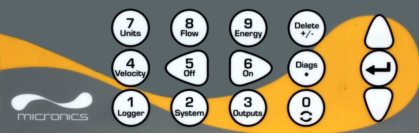
Micronics UF3300 User Manual

1.5 Keypad
The instrument is configured and controlled via a 15-key tactile membrane keypad, as shown in
Figure 5.
 Numerical keypad with Scroll up
 dual function keys

 ENTER
 (SELECT)

 Scroll
 down
Figure 5 UF3300 keypad

1.5.1 Dual Function Numerical Keypad
The block of keys shown in the centre of the keypad in Figure 5 are dual function keys. They can be
used to enter straight-forward numerical data within menus or provide quick access to frequently
used menus or commands from the Read Flow/Velocity/Energy display screens. There is a
distinction between short key presses (< 1.5 seconds) and long key presses (≥ 1.5 seconds). All key
press operations in this document are short key presses unless otherwise stated.
NOTE: DEPENDING ON THE INSTALLED OPTIONS, SOME OF THE FEATURES ACCESSED
BY THESE KEYS MAY BE UNAVAILABLE.

 Key Use

 0 Circulate between flow, velocity and optionally energy screens (via a short press
 when reading flow, energy or velocity), enter the zero-flow setting screen (long press
 when reading flow), or freeze and un-freeze diagnostic values in the Diagnostic
 screen

 1 Display the Logger menu (see page 41)

 2 Display the System Settings menu (see page 24)

 3 Display the Output Board Setup menu (see page 44)

 4 Switch to the Read Velocity display from the Read Flow display or Read Energy
 display
 (Heat Meter versions only)

 5 No function - reserved for future use

Page 8 Issue 1.0 April 2021
Micronics UF3300 User Manual

 Key Use

 6 No function - reserved for future use

 7 Cycle through the available display units

 8 Switch to the Read Flow display from the Read Velocity display or Read Energy
 display
 (Heat Meter versions only)

 9 Heat Meter versions only: switch to the Read Energy display from the Read
 Velocity display or Read Flow display

 Delete No shortcut function: within text entries, deletes character to left of flashing cursor.
 +/- Deletes alarms when activated, or return to the MAIN MENU from the Summary
 screen

 Diags Display the Diagnostics screen (see page 65)
 .

Numeric Entry
Entry of numeric values is straightforward using the digits, decimal point and +/- keys. Press the +/-
key as the first character to enter a negative value. Pressing it again will change the sign again.
Then enter the number desired using the digits keys. The decimal place is optional, but not if you
are entering a value containing an exponent. The first press of the decimal point will result in a ‘.’.
The second press will result in an ‘E’. Press ENTER to terminate entry and fix the value.
An example of exponential notation follows:
1. Enter the number using digits and the mandatory decimal point
 (for example, 1 must be entered as 1.0).
2. Add another decimal point at the place where you wish the exponent to appear.
3. Add the exponent as a number.
For example, using this technique, 101000 (1.01×10⁵) would be entered as the sequence “1.01.5”
and this would appear as 101000 l/min.

1.5.2 Menus and the Menu Selection Keys
To navigate the UF3300’s menu system, use the three keys on the right-hand side of the keypad:
1. Use the UP & DOWN arrow keys to scroll through a menu list and select a menu item, as
 indicated by an arrow-shaped cursor on the left-hand side of the screen.
2. Edit or open the active menu choice by pressing the ENTER key.
3. Use the UP and DOWN arrow keys to cycle through the available options or, for numerical
 settings, use the keypad to enter the required value.
4. Press the ENTER key to confirm the new setting.

Issue 1.0 April 2021 Page 9
Micronics UF3300 User Manual

Some menus have more options than can be shown on the screen at the same time, in which case
the ‘overflowed’ choices can be brought into view by continuing to scroll beyond the lowest visible
item.
Menus generally ‘loop around’ if you scroll beyond the first or last items. Sometimes, this is the
quickest route to find the Exit command to close a menu.
If you select Exit on any menu it usually takes you back up one level in the menu hierarchy, but in
some cases, it may go directly to the Read Flow screen.
Menu items ending with “..” generally indicate that selection of this item will take you to another
screen.

 UF3300 MAIN 26-02-20 13:45:42
 ↱ Quick start..
 View / Edit Site Data..
 Setup Instrument..
 Data Logger..
 Read Flow..
 Read Energy..

Figure 6 Main menu
 (Read Energy and Data Logger options available with heat meter versions only)

Page 10 Issue 1.0 April 2021
Micronics UF3300 User Manual

2 INSTALLATION

2.1 Positioning
The UF3300 instrument should be installed as close as conveniently possible to the pipe-mounted
ultrasonic sensors. Standard transducer cables are 5 metres in length with 10 metre cables being
optionally available. Where, for operational reasons, it is not possible to mount the instrument this
close to the sensors, bespoke cables of up to 100m can be provided – consult Micronics Ltd for
further information and availability.
A suitable mains supply must be available to power the instrument (an optional 24V AC/DC. supply
module is available). The external supply must be suitably protected and connected via an
identifiable isolator. A 500mA fuse is fitted internally in the instrument’s input supply line.

2.2 Mounting
Ideally the UF3300 enclosure should be fixed to a wall using three M4 screws.
1. Remove the UF3300 terminal cover.
2. Fix a screw into the wall at the required point to align with the mounting keyhole on the back of
 the enclosure.
3. Attach the enclosure to the wall using the keyhole screw mounting.
4. Align the enclosure (see Figure 7) then mark out the positions for the two remaining screw
 fixings through the slots near the bottom corners of the enclosure. Then remove the enclosure,
 and drill (and plug) the fixing points.
5. Clear the site of any dust/debris then mount the enclosure on the wall.

 M4 keyhole

 141mm

 198mm

Figure 7 UF3300 mounting dimensions

Issue 1.0 April 2021 Page 11
Micronics UF3300 User Manual

2.3 Connections
This section explains how to connect power and signal cables to the terminal blocks inside the wall
mount unit.
The transducer cables attach to sockets on the left side of the terminal block. Other cables enter the
instrument through the four cable glands provided and are connected to terminal blocks which are
located behind a safety cover (Figure 8).
To make power, PT100 and output connections:
1. Remove the terminal block cover by unfastening the two retaining screws.
2. Route the control and monitoring cables through the two smaller cable glands.
3. Cut the wires to length, strip back the insulation by approximately 10mm and connect them into
 the required terminals as described above and identified in Figure 8.
4. On completion, tighten the cable glands to ensure the cables are held securely.
5. Refit the terminal block cover.

 4-20mA Pulse(outputs 1, 2 & 3) PT100 Sensors Power
Figure 8 Terminal blocks

2.3.1 Power Supply
The instrument can be powered from a mains supply (100 - 240V AC., 50/60Hz) or from a 24V
AC/DC supply if it is fitted with a 24V supply module.
1. Route the power cable through one of the two cable glands on the right hand side of the
 instrument, below the power connection terminals, using the gland most suitable for the cable
 diameter.
2. Cut the wires to length, strip back the insulation by approximately 10mm and connected to them
 into the correct power supply terminals identified in Figure 8.
3. On completion, tighten the cable glands to ensure the cables are held securely.

Page 12 Issue 1.0 April 2021
Micronics UF3300 User Manual

 LETHAL VOLTAGES!
ENSURE THE POWER CABLE IS ISOLATED FROM THE MAINS SUPPLY.
DO NOT APPLY MAINS VOLTAGE WITH THE TERMINAL COVER REMOVED. EXTERNAL
POWER SUPPLY MUST BE CLASS 2 RATED.

 IMPORTANT: IT IS THE RESPONSIBILITY OF THE INSTALLER TO CONFORM TO THE
REGIONAL VOLTAGE SAFETY DIRECTIVES WHEN CONNECTING THE UF3300 TO A POWER
SUPPLY USING A MAINS-RATED TRANSFORMER.

 SUPPLY EARTHING.
IF THE EQUIPMENT IS POWERED FROM A 24V AC SUPPLY THEN THE SUPPLY MUST BE
ISOLATED FROM EARTH.

2.3.2 Control & monitoring cables
Depending on the fitted options, any of the following control and monitoring cables may be required:
• Current Output
 A 4-20mA, 0-16mA, or 0-20mA monitoring signal output at terminal mA+ and mA-.(mA+ is the
 current output terminal and mA- is the return terminal).
• Pulse Output
 An opto-isolated pulse output is available at terminals PULSE+ and PULSE- (PULSE+ is the
 pulse output terminal and PULSE- is the return terminal).
• Alarm Outputs
 Two programmable, multifunction alarm outputs are available using MOSFET, SPNO relays.
 The relays are rated at 48V/500mA continuous load, and are connected to terminals ALARM1+,
 ALARM1-, ALARM2+ and ALARM2- respectively.
Using the instrument’s menu system (see page 44), you can:
• Select the current output function Off/On
• Select the current output range (set the current range, where 4-20mA, 0-20mA, 0-16mA are
 common ranges), but the device is capable of generating currents of up to 24mA
• Calibrate the current output signal to a required flow range
• Select the alarm cause (and alarm current for the current output)
• Set a trigger value for the alarm when it is associated with Under Value or Exceeds Value
• Set current trim values to accommodate any inaccuracies in the user’s system

Issue 1.0 April 2021 Page 13
Micronics UF3300 User Manual

2.3.3 USB Connector
A USB connector is available at the left-hand side of the enclosure. This can be used to download
logged data onto a USB memory stick (see page 42).

Figure 9 USB socket on left side of UF3300 enclosure

Page 14 Issue 1.0 April 2021
Micronics UF3300 User Manual

2.4 Positioning the Transducers
For accurate measurements, the transducers must be installed at a position where the fluid flows
uniformly. Flow profile distortions can result from upstream disturbance such as bends, tees, valves,
pumps and other similar obstructions. To ensure a uniform flow profile, the unit must be mounted
away from any cause of flow disturbance.
As a guide, we suggest this is best achieved by ensuring there is a straight length of pipe upstream
of the transducers of at least 10 times the pipe diameter, and 5 times the pipe diameter on the
downstream side, as shown in Figure 10, but this may vary. Flow measurements can be made on
shorter lengths of straight pipe, but when the transducers are mounted this close to any obstruction
the resulting inaccuracies can be unpredictable.

 DOWNSTREAM UPSTREAM
 5 x pipe 10 x pipe
 diameter diameter

 45°
 Uniform Flow Profile Distorted Flow Profile

 Air

 Sludge

Figure 10 Location of unit

To obtain the most accurate results, the condition of both the liquid and the pipe must be suitable to
allow ultrasound transmission along the predetermined path.

Issue 1.0 April 2021 Page 15
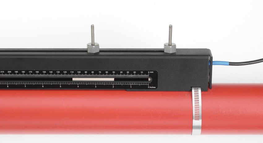
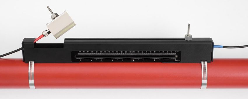
Micronics UF3300 User Manual

In many applications, an even flow velocity profile over a full 360° is unattainable due, for example,
to the presence of air turbulence at the top of the flow and also possibly sludge at the bottom of the
pipe. Experience has shown that the most consistently accurate results are achieved when the
sensors are mounted at 45°with respect to the top of the pipe.
IMPORTANT: DO NOT EXPECT TO OBTAIN ACCURATE RESULTS IF THE UNIT IS
POSITIONED CLOSE TO ANY OBSTRUCTION THAT DISTORTS THE UNIFORMITY OF THE
FLOW PROFILE. MICRONICS LTD ACCEPTS NO RESPONSIBILITY OR LIABILITY IF
PRODUCT HAS NOT BEEN INSTALLED IN ACCORDANCE WITH THESE INSTRUCTIONS.

2.5 Attaching the Transducers
Type ‘A’ or ‘B’ transducers are attached to the pipe using the adjustable guide rail assembly shown
in Figure 11. The guide rail itself is secured to the pipe using two wrap-around steel bands. For
convenience, an imperial (inches) and metric (millimetres) ruler is attached to the side plate of the
guide rail. Once the guide rail assembly is fully assembled the transducers are locked into position
by tightening the transducer clamp.
NOTE: WHEN USING THE UF3300 IN THE ‘DIAGONAL’ MODE, OR IN ‘REFLEX’ MODE ON
PIPES OVER 350 MM DIAMETER, TWO GUIDE RAILS ARE REQUIRED WITH A TRANSDUCER
MOUNTED IN EACH ONE – SEE PAGE 20 FOR DIAGONAL MODE CONNECTION DETAILS.

2.5.1 Cleaning the Contact Area
Prepare the pipe by degreasing it and removing any loose material or flaking paint in order to obtain
the best possible surface. A smooth contact between pipe surface and the face of the sensors is an
important factor in achieving a good ultrasound signal strength and therefore maximum accuracy.

2.5.2 Attaching the Guide Rail to the Pipe
Position the guide rail horizontally on the pipe at 45° with respect to the top of the pipe and secure it
in position using the supplied stainless steel banding, as shown in Figure 11.
NOTE: IN THE FOLLOWING PROCEDURE THE GUIDE RAIL IS INSTALLED WITH THE
RECTANGULAR OPENING FACING TOWARDS THE UPSTREAM END OF THE PIPE.

 Upstream Downstream

Figure 11 Attaching the guide rail

Page 16 Issue 1.0 April 2021
Micronics UF3300 User Manual

2.5.3 Fitting the Transducers
1. Tighten each transducer clamp clockwise until it is close to the top of the transducer (Figure 12,
 left). This is necessary in order to prevent the acoustic couplant touching the pipe when the
 transducer is initially inserted into the guide rail – as described below.
2. Using the supplied syringe applicator, apply a 3mm bead of acoustic couplant to the base of
 both transducers (Figure 12, right).

 Transducer clamp

 Transducer
 Cable connector

 Couplant

Figure 12 Transducer components (left); applying couplant (right)

3. Thread the downstream transducer cable (blue) through the right-hand end of the guide rail and
 up through the rectangular opening at the top left-hand end of the guide rail, as shown in Figure
 13.
4. Connect the downstream cable (blue) to one of the transducers.
NOTE: WHEN CARRYING OUT THE FOLLOWING STEPS HANDLE THE TRANSDUCER
ASSEMBLY WITH CARE TO AVOID SMEARING THE ACOUSTIC COUPLANT ON THE PIPE
WHILST ATTACHING THE TRANSDUCER TO THE GUIDE RAIL.

Figure 13 Installing downstream (blue) transducer

5. Carefully slide the downstream transducer assembly along the guide rail until the inner face of
 the transducer is aligned with the '0' mark on the ruler scale (Figure 14).

Issue 1.0 April 2021 Page 17
Micronics UF3300 User Manual

 Align edge of transducer with ‘0’ on ruler scale

Figure 14 Aligning edge of downstream transducer (blue) with zero on ruler scale

6. Lower the transducer onto the pipe by turning the transducer clamp anti-clockwise until it is
 ‘finger tight’ (do not use a spanner).
7. Thread the upstream signal cable (red) through the left-hand end of the mounting rail and
 connect it to the second transducer (Figure 15).
8. Carefully lower the transducer assembly through the rectangular opening until the slots in the
 side of the transducer clamp align with the edges on the top of the guide rail.

Figure 15 Installing upstream transducer (red)

9. Position the upstream transducer so that the inner face of the transducer is set to the required
 separation distance on the ruler, as shown in Figure 16.
NOTE: THE SEPARATION DISTANCE FOR A PARTICULAR APPLICATION CAN BE FOUND
USING THE ‘QUICKSTART’ MENU SEE PAGE 27.

Page 18 Issue 1.0 April 2021
Micronics UF3300 User Manual

 Calculated separation distance

Figure 16 Settinging transducer separation

10. Lower the transducers onto the pipe by turning each transducer clamp anti-clockwise until it is
 ‘finger tight’ (do not use a spanner). Figure 17 shows the final position of the transducers when
 the transducer clamps are fully tightened.

Figure 17 Lowering transducers onto pipe

11. Connect the transducer signal cables to the UF3300 instrument – i.e. with the RED cable
 connected to the upstream transducer connector and the BLUE cable to the downstream
 transducer connector.
NOTE. IF YOU OBSERVE NEGATIVE FLOW, SWAP THE RED AND BLUE CABLES AT THE
SENSOR END.

Issue 1.0 April 2021 Page 19
Micronics UF3300 User Manual

2.5.4 Fixing Transducers in Diagonal Mode
This mode of operation requires two transducer guide rails fitted on opposite sides of the pipe (fitted
on a 45° axis with respect to the top of the pipe as in Reflex Mode). If the required transducer
separation is 230mm or less, the guide rails can be fitted using the same stainless steel bands (see
Figure 18a). For greater transducer separation, the guide rails may need to be installed separately
(see Figure 18b). In this case, it is necessary to accurately mark out the required positions to ensure
that the transducers are correctly positioned and aligned along the axis of the pipe, directly opposite
each other on a 45° axis with respect to the top of the pipe, and at the required separation.
To position the transducers, obtain and note the separation distance between the transducers using
the Quick Start menu (see page 27).
Prepare the transducers with couplant as described in Section 2.5.3.
Required transducer separation 230mm or less:
1. Position the two guide rails horizontally on the pipe at 45° with respect to the top and bottom of
 the pipe and secure in position using the supplied stainless steel banding (see Figure 18a).
2. Follow the instructions provided for Reflex Modes, fitting the downstream transducer in the
 lower guide rail and the downstream transducer in the top guide rail.

 (a) Required transducer separation 230mm

 Separation distance

 FLOW

Figure 18 Guide rail positioning for Diagonal Mode

Required transducer separation greater than 230mm:

Page 20 Issue 1.0 April 2021
Micronics UF3300 User Manual

1. Position the upstream guide rail horizontally on the pipe at 45° with respect to the top of the
 pipe and secure it in position using the supplied stainless steel banding.
2. Fit the upstream transducer into the guide rail but do not fasten it in position yet.
3. Position the downstream guide rail at the approximate location to give the required separation
 under the pipe. For example, if the required separation is 450mm, align the guide rail so that the
 zero marks on the two guide rails are 400mm apart. The remainder can then be accounted for
 by sliding the upstream transducer to the 50mm mark (see Figure 18b). This allows for any fine
 adjustments that may be necessary during use.
4. Fit the downstream transducer so that the inner face is aligned with the zero mark on the guide
 rail.
5. Adjust the position of the upstream transducer so that the overall separation distance is
 correctly achieved.
6. Lower the two transducers onto the pipe by turning the transducer clamps anti-clockwise.

Marking out Large Pipes for Diagonal Mode
This is a method for marking out perpendicular circumferences on large pipes to ensure that guide
rails are positioned accurately:
1. Wrap a length of material such as chart paper around the pipe, aligning the edges of the paper
 precisely at the overlap. With the edge of the chart paper being parallel, either edge describes a
 circumference around the pipe that is perpendicular to the pipe axis.
2. Mark the chart paper exactly where it overlaps. Then, after removing the paper from the pipe,
 fold the measured length in half keeping the edges parallel. The fold line now marks a distance
 exactly half way around the pipe.
3. Put the paper back on the pipe and use the fold line to mark the opposite side of the pipe.

Issue 1.0 April 2021 Page 21
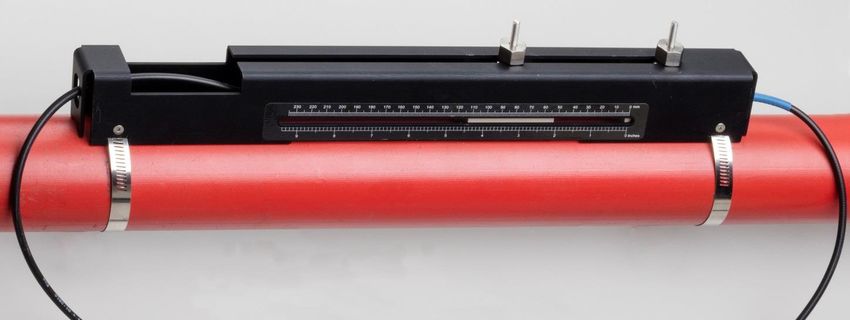
Micronics UF3300 User Manual

2.6 Connecting Temperature Probes (UF3300 HM Models Only)
The temperature sensors must be located at the flow and return of the system that is being
monitored. The area of pipe where they are to be attached must be free of grease and any
insulating material. It is recommended that any coating on the pipe is removed so that the sensor
has the best possible thermal contact with the pipe4.
For optimum reliability on boiler applications, the flow measurement needs to be made on the cold
side of the system. For optimum reliability in chiller applications, the flow measurement needs to be
made on the warmer side of the system.

Figure 19 UF3300 Heat Meter Temperature Probe Positioning (Heater system)

4 It must be kept in mind that this is the reading on the outside of the pipe, which may vary significantly from
the actual fluid temperature, especially if the pipe material is of some type of insulating material. This does not
necessarily invalidate energy readings since the readings are dependent on the temperature differential, not
the absolute temperature. It is the responsibility of the installer to ensure the differential temperature readings
are as accurate as possible. This may necessitate covering the sensors with insulating material to ensure
drafts and differences in ambient temperature are minimised for both sensors.

Page 22 Issue 1.0 April 2021
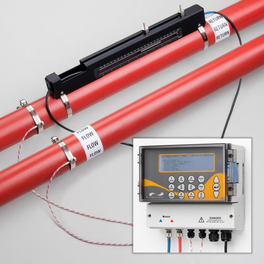
Micronics UF3300 User Manual

2.7 Calibrate the PT100 Sensors (Heat Meter versions only)
IMPORTANT: THE PT100 SENSORS MUST BE BALANCED BEFORE INITIAL USE, USING THE
PROCEDURE DESCRIBED BELOW AND USED WITH THE CABLE LENGTH SUPPLIED.
EXTENDING OR SHORTENING THE CABLES WILL NEGATE THE CALIBRATION OF THE
SENSORS.
Please refer to Chapter 8, page 54.

2.8 Attach the PT100 Sensors (Heat Meter versions only)
The PT100 sensors must be located at the input and output of the system that is being monitored.
The area of pipe where they are to be attached must be free of grease and any insulating material.
It is recommended that any coating on the pipe is removed so that the sensor has the best possible
thermal contact with the pipe.
Clamp the sensors in position using the supplied stainless-steel cable ties.

Figure 20 Fully assembled UF3300 (heat meter version)

Issue 1.0 April 2021 Page 23
Micronics UF3300 User Manual

2.9 Switching on for the First Time
 READ FLOW DD-MM-YY HH:MM:SS
When power is applied, the unit passes through its Q60.0%
initial booting sequence and then displays the Flow
screen.
Press the ENTER key to display the Main menu. +
 27.540 27.0 l
 l/min

 - 0.1 l

2.9.1 Checking System Health
This operation should be checked after powering up the unit for the first time, but it is useful to
check periodically that all systems are operating properly, especially if errors were reported when
entering the Main menu.
1. From the Main menu, use the Up and Down scroll keys to select Setup Instrument. Press the
 ENTER Key.
2. A list of options will be displayed depending on the UF3300 configuration. It should be noted
 that a status message will appear to the right of the option name. If the sub-system
 implementing the option is working correctly, the status will read “OK”. If any subsystem has a
 fault, two dashes will be visible.
3. If a subsystem is NOT reading OK at start-up, try restarting the UF3300 by turning it off then on
 again. If the error persists, contact your distributor or return the item for repair.

2.9.2 Selecting a Language
English is the default display language. German, French and Spanish options are also available. To
change the language:
 UF3300 MAIN DD-MM-YY HH:MM:SS
1. From the Main menu, use the Up and Down
 Quick start..
 scroll keys to select Setup Instrument. Press View / Edit Site Data..
 the ENTER Key. With System selected in the →Setup Instrument..
 Options menu, press the ENTER Key. Data Logger..
 Read Flow..
 Read Energy..
 Alternatively, from a Read Flow/Velocity/Energy
 screen, press the SYSTEM key (2). The System
 Option DD-MM-YY HH:MM:SS
 Settings menu is displayed.
 ↱System..
2. Use the UP/DOWN arrow keys to select Power..
 Language. Press the ENTER key. Output..
 Heat-Meter..
3. Use the UP/DOWN arrow keys to scroll through Logger..
 Primary Flow..
 the available options.
4. With the required language highlighted, press the ENTER key.
5. Use the UP/DOWN arrow keys to select Save Setup & Exit. Press the ENTER key.
The selected language is now active for all screens.

Page 24 Issue 1.0 April 2021
Micronics UF3300 User Manual

2.9.3 Setting the Date & Time
 System Settings DD-MM-YY H:MM:SS
1. From the MAIN menu, use the Up and Down
 scroll keys to select Setup Instrument. Press Lock-screen Timeout 90 sec
 Back-light mode ON
 the ENTER Key. With System selected in the Back-light Timeout 75 sec
 Options menu, press the ENTER Key. ↱Set Date & Time..
 Reset Totals..
 Damping 10 sec
 Alternatively, from a Read Flow/Velocity/Energy
 screen, press the SYSTEM key (2). The System
 Settings menu is displayed.
2. Use the UP/DOWN arrow keys to select Set Set Date & Time DD-MM-YY HH:MM:SS
 Date & Time. Press the ENTER key. ↱Set Date & Time DD-MM-YY.HH:MM:SS
 The Set Date & Time menu is displayed. Mode DD-MM-YY
 Exit
3. The instrument is configured to display dates in
 DD-MM-YY format. Proceed to step 6 unless
 you prefer to use MM-DD-YY format.
4. Use the UP/DOWN arrow keys to select Mode. Press the ENTER key.
5. Use the UP/DOWN arrow keys to choose the required format: DD-MM-YY or MM-DD-YY. Press
 the ENTER key. The date and time format will immediately be updated.
6. Use the UP/DOWN arrow keys to select Set Date & Time. Press ENTER. A flashing cursor
 appears under the first date number. Enter the date and time sequence in DD-MM-YY-HH-MM-
 SS format then press the ENTER key.
7. Scroll down and select Exit then press the ENTER key to return to the MAIN menu.
NOTE: IF YOU MAKE A MISTAKE WHEN ENTERING THE DATA PRESS THE DELETE KEY TO
MOVE THE CURSOR BACK TO THE NUMBER YOU WISH TO CHANGE, THEN CONTINUE. IF
YOU ENTER AN INVALID NUMBER AN ‘ERR:INVALID DATE OR TIME!’ OR ‘BADLY
FORMATTED DATE OR TIME’ ERROR MESSAGE IS DISPLAYED ON THE SECOND LINE OF
THE SCREEN. IF THIS OCCURS REPEAT THE SET DATE/TIME PROCEDURE.

2.9.4 Enabling/Disabling the Backlight System Settings DD-MM-YY HH:MM:SS

The backlight can be selected to be OFF, TIMED ↱Back-light mode On
(illuminated until a set interval of keypad inactivity Back-light Timeout 75 sec
 Audible keypress Off
occurs), or ON permanently. If the backlight is not Set Date & Time..
required it is recommended that you disable it or use Display Total Both
 Reset Totals..
the TIMED option.
1. From the MAIN menu, use the Up and Down scroll keys to select Setup Instrument. Press the
 ENTER Key. With System selected in the Options menu, press the ENTER Key.

 Alternatively, from a Read Flow/Velocity/Energy screen, press the SYSTEM key (2).
 The System Settings menu is displayed.
2. Use the UP/DOWN arrow keys to select Back-light mode. Press the ENTER key.
3. Use the UP/DOWN arrow keys to scroll through the available options: On/Timed/Off.
4. With the chosen mode selected, press the ENTER key.

Issue 1.0 April 2021 Page 25
Micronics UF3300 User Manual

5. If you select TIMED, use the UP/DOWN arrow keys to select to Back-light Timeout. Press the
 ENTER key.
6. Use the keypad to enter the required timeout interval (5-120s). Press the ENTER key.
7. Select Save Setup & Exit then press the ENTER key to return to the Options menu.
8. Select Exit then press the ENTER key to return to the Main menu.

2.9.5 Enabling/Disabling Audible Keypress
When enabled, the Audible keypress option
 System Settings DD-MM-YY HH:MM:SS
provides feedback that a key has been released:
 ↱Audible keypress ON
• When a key is pressed for a short period of time, Set Date & Time..
 Display Total Both
 a very short beep will be heard. Reset Totals..
 Damping Mode Fixed
• When a key is pressed for a long time, a beep of Damping Time 10 sec
 up to half a second will be heard.
To change the Audible keypress option:
1. From the MAIN menu, use the Up and Down scroll keys to select Setup Instrument. Press the
 ENTER Key. With System selected in the Options menu, press the ENTER Key.

 Alternatively, from a Read Flow/Velocity/Energy screen, press the SYSTEM key (2). The
 System Settings menu is displayed.
2. Use the UP/DOWN arrow keys to select Audible keypress. Press the ENTER key.
3. Use the UP/DOWN arrow keys to scroll through the available options: On/Off.
4. With the chosen mode selected, press the ENTER key.
5. Note that key beeps will be active immediately
6. Select Save Setup & Exit then press the ENTER key to return to the Options menu.
7. Select Exit then press the ENTER key to return to the Main menu.

Page 26 Issue 1.0 April 2021
Micronics UF3300 User Manual

3 USING THE QUICK START MENU
If you want to perform a ‘one-off’ flow reading at a particular pipe location the Quick start wizard
provides the simplest way to set up the UF3300 system and access the FLOW READING screen.
If the point at which you intend to take the measurement is likely to require regular monitoring it is
best to set it up as a ‘Site’ within the UF3300, which then stores the site parameters (See Chapter
4).
Before you can use the UF3300 system you need to obtain the following details (this information will
be required when setting up the Quick start wizard):
• Pipe outside diameter or circumference.
• Pipe wall thickness and material.
• Pipe lining thickness and material.
• Type of fluid.
• Fluid temperature.

3.1 Entering the Site Data UF3300 MAIN DD-MM-YY HH:MM:SS

 ↱Quick start..
1. Select Quick start from the MAIN MENU and View/Edit Site Data..
 press the ENTER key. You will then be Setup Instrument..
 presented with a series of screens in which to Data Logger..
 Read Flow..
 enter the data mentioned above. Read Energy..

2. Enter the pipe’s outside diameter (15 – 2000
 mm or its circumference (47.1 – 6283.2 mm). Pipe Outside Di DD-MM-YY HH:MM:SS
 When you enter one value the other is ↱Pipe outside diameter 114.30 mm
 calculated from it. Pipe circumference 359.08 mm
 Continue..
 Main Menu..
 Select CONTINUE and press the ENTER key.

 Pipe Wall Thick DD-MM-YY HH:MM:SS
3. Enter the pipe wall thickness (0.5 – 50 mm).
 ↱Pipe wall thickness 8.00 mm
 Continue..
 Select CONTINUE and press the ENTER key. Main Menu..

4. Choose the pipe wall material: Plastic/Cast
 Iron/Ductile Iron/Copper/Brass/Concrete/ Pipe Wall Mater DD-MM-YY HH:MM:SS

 Glass/Other (m/s)/Mild Steel/ ↱Pipe wall material Plastic
 Continue..
 S'less Steel 316/S'less Steel 303. Main Menu..
 If the material is not listed, select Other (m/s)
 and enter the propagation rate of the pipe wall
 material in metres/sec. Contact Micronics if this
 is not known.

 Select CONTINUE and press the ENTER key.

Issue 1.0 April 2021 Page 27
Micronics UF3300 User Manual

 Identify the pipe lining material from the Pipe Lining DD-MM-YY HH:MM:SS
 following options: ↱Lining material Glass
 None/Rubber/Glass/Epoxy/Concrete/ Continue..
 Main Menu..
 Other (m/s). If the material is not listed, select
 Other (m/s) and enter the propagation rate of
 the pipe wall material in metres/sec. Contact
 Micronics if this is not known.
 Pipe Lining Thi DD-MM-YY HH:MM:SS
5. Select CONTINUE and press the ENTER key.
 ↱Pipe Lining thickness 1.0 mm
6. If no lining material was entered, go to step 7. Continue..
 Main Menu..
 Otherwise, enter the lining thickness (0 – 40
 mm).

 Select CONTINUE and press the ENTER key.
7. Select the fluid type from the following options: Fluid Type DD-MM-YY HH:MM:SS
 Water/Glycol/water 50%/Glycol/water ↱Select fluid type Water
 30%/Lubricating oil/Diesel/Freon/Other (m/s). If Continue..
 the fluid is not listed, select Other (m/s) and Main Menu..

 enter the propagation rate of the fluid in
 metres/sec. Contact Micronics if this is not
 known.
 Note: If Other is selected, enter the speed of sound (SoS) in metres per second, of the wall
 material. After entry of the SoS, the user will be taken to the following screen as would have
 been the case if another selection was made.

 Select CONTINUE and press the ENTER key. Fluid Temperatu DD-MM-YY HH:MM:SS

8. Enter the fluid temperature (-30 – 135.0 °C) at ↱Fluid Temperature 14.0°C
 Continue..
 the point the meter is installed. Main Menu..

 Select CONTINUE and press the ENTER key.

9. Heat Meter Versions Only: Specify how the
 Heat-meter DD-MM-YY HH:MM:SS
 Heat meter is configured: Hot Sensor/Cold
 Sensor/Fluid Temperature. ↱Installation Side Hot Sensor
 Sensor Type PT100
 Program the unit with the temperature of the Continue..
 Main Menu..
 fluid at the point where the flow meter is
 installed to account for any variations in relative
 density and specific heat capacity. If the meter is installed at a point some way from either the
 hot of cold sensor, select the temperature entered in the previous step.

 Select CONTINUE and press the ENTER key.

Page 28 Issue 1.0 April 2021
Micronics UF3300 User Manual

10. The Summary screen is displayed. This displays
 Summary DD-MM-YY HH:MM:SS
 a summary of the entered parameters and
 Site: QuickStart
 informs you of the type of sensor to be used, the Sensor separation: 69.9mm
 mode of operation and the distance to set up Pipe OD: 114.3mm, ID 98.3mm
 Sensor Type A-ST, Mode: Reflex
 between the sensors. Fluid type: Water @14.0°C
 In this example, A-ST (A standard) sensors are Press ↵ to continue,△▽to select sens.
 recommended, operating in the ‘Reflex’ mode,
 spaced at 69.9mm apart.
NOTE: DO NOT PRESS THE ENTER KEY UNTIL THE CORRECT TRANSDUCERS ARE FITTED
AND CONNECTED TO THE INSTRUMENT. IF THE DATA CONTAINS A MISTAKE, PRESS THE
DELETE KEY TO RETURN TO THE MAIN MENU AND RESTORE THE PREVIOUS SETTINGS.

11. If you prefer to use a different configuration, Sensors DD-MM-YY HH:MM:SS

 press the UP or DOWN arrow key to select a ↱Sensor Set A-ST
 Sensor Mode Reflex
 different sensor set and mode. Return to Summary Screen..
 Main Menu..

NOTE: THE SENSORS SCREEN WILL BE DISPLAYED AUTOMATICALLY IF THE ENTERED
PIPE OD AND/OR TEMPERATURE ARE NOT VALID FOR THE CURRENTLY SELECTED
SENSORS.

3.2 Attaching and Connecting the Flow Sensors
1. Fit the designated sensors to the pipe using the appropriate guide rails as described in Section
 2.2. Take great care to set the separation distance as accurately as possible.
2. Connect the red and blue coaxial cables between the sensors and the test instrument, ensuring
 that the red connector on the instrument is connected to the ‘upstream’ sensor.

3.3 Taking a Flow Reading READ FLOW DD-MM-YY HH:MM:SS
 Q60.0%
1. Once the transducers have been fitted and
 connected, press the ENTER key on the
 Summary screen.
 +
 27.540 27.0 l
 l/min

2. This will take you to the FLOW READING
 - 0.1 l
 screen via a signal-checking screen.
3. Check that the indicated signal strength on the left of the screen is at least 2 bars (ideally 3 or
 4). If less than 2 bars are shown it indicates there could be a problem with the transducer
 spacing, alignment or connections; or it could be due to an application problem.
4. The Q value indicates the signal quality and should have a value of 60% or greater. Signal Q is
 a mixture of the Signal to Noise Ratio (SNR) and signal timing accuracy. This is the best
 measure of system performance.
The Read Flow screen is used most frequently during normal monitoring operation. It shows the
instantaneous fluid flow together with totalised values (when enabled).

Issue 1.0 April 2021 Page 29
You can also read