UM2426 User manual X-CUBE-CELLULAR cellular connectivity Expansion Package for STM32Cube - STMicroelectronics
←
→
Page content transcription
If your browser does not render page correctly, please read the page content below
UM2426
                                                                           User manual
   X-CUBE-CELLULAR cellular connectivity Expansion Package for
                                                  STM32Cube

           Introduction
           This user manual describes the content and use of the X-CUBE-CELLULAR cellular
           connectivity Expansion Package for STM32Cube.
           The X-CUBE-CELLULAR Expansion Package enables connectivity over cellular networks.
           The network access technology depends on the cellular modem used: 2G, 3G, LTE Cat M1,
           or NB-IoT (also known as NB1). The cellular connectivity framework exposes standard APIs
           for easy integration of cloud connectors using the HTTP protocol.
           The X-CUBE-CELLULAR Expansion Package for STM32Cube provides an application
           example that connects and subscribes to cloud services using the HTTP protocol in order to
           report data from the device to the server, as well as to receive commands from the remote
           server. Two additional applications are provided as examples: echo (exchanges data with a
           remote server using TCP or UDP), and ping (tests the access to a remote machine).
           X-CUBE-CELLULAR is available for the following hardware (refer to Chapter 1 for details):
           • P-L496G-CELL01 cellular-to-cloud pack with STM32L496AG-based Discovery host
             board and UG96 modem (2G / 3G) add-on board
           • P-L496G-CELL02 cellular-to-cloud pack with STM32L496AG-based Discovery host
             board and BG96 modem (LTE Cat M / NB-IoT / 2G fallback) add-on board
           • B-L475E-IOT01A IoT Discovery board and BG96 modem add-on board
           • B-L475E-IOT01A IoT Discovery board and Sequans® GM01Q modem
           • 32L496GDISCOVERY Discovery board and GM01Q-STMOD, UG96, or BG96 modem
             add-on board
           The main features of the X-CUBE-CELLULAR Expansion Package are:
           •   Ready-to-run firmware examples using the 2G, 3G, LTE Cat M1, or NB-IoT protocols
           •   Configuration of the HTTP connection to the IoT platform and cellular connectivity
           •   Cellular connection
           •   Reporting of such values as temperature, humidity, and pressure
           •   Network radio level reporting
           •   Testing of access to a remote machine
           •   Connection and data exchange using the TCP or UDP socket protocols

May 2019                                   UM2426 Rev 4                                             1/51
                                                                                             www.st.com    1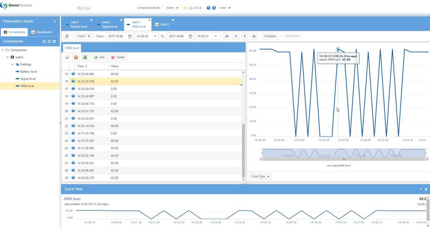
Contents                                                                                                                 UM2426

Contents

1          General information . . . . . . . . . . . . . . . . . . . . . . . . . . . . . . . . . . . . . . . . . 6
           1.1      Terms and definitions . . . . . . . . . . . . . . . . . . . . . . . . . . . . . . . . . . . . . . . . . 6
           1.2      References . . . . . . . . . . . . . . . . . . . . . . . . . . . . . . . . . . . . . . . . . . . . . . . . . 8

2          Important note regarding the security . . . . . . . . . . . . . . . . . . . . . . . . . . 9

3          Service connectivity description . . . . . . . . . . . . . . . . . . . . . . . . . . . . . . 10

4          Package description . . . . . . . . . . . . . . . . . . . . . . . . . . . . . . . . . . . . . . . . 11
           4.1      General description . . . . . . . . . . . . . . . . . . . . . . . . . . . . . . . . . . . . . . . . . .11
           4.2      Modem socket versus LwIP . . . . . . . . . . . . . . . . . . . . . . . . . . . . . . . . . . . .11
           4.3      Architecture . . . . . . . . . . . . . . . . . . . . . . . . . . . . . . . . . . . . . . . . . . . . . . . .11
                    4.3.1       Architecture concept . . . . . . . . . . . . . . . . . . . . . . . . . . . . . . . . . . . . . . . 12
                    4.3.2       Static architecture view . . . . . . . . . . . . . . . . . . . . . . . . . . . . . . . . . . . . . 14
                    4.3.3       Dynamic architecture view . . . . . . . . . . . . . . . . . . . . . . . . . . . . . . . . . . . 16
           4.4      X-CUBE-CELLULAR Expansion Package description . . . . . . . . . . . . . . . 20
           4.5      Folder structure . . . . . . . . . . . . . . . . . . . . . . . . . . . . . . . . . . . . . . . . . . . . 21
           4.6      Reset push-button . . . . . . . . . . . . . . . . . . . . . . . . . . . . . . . . . . . . . . . . . . 22
           4.7      Real-time clock . . . . . . . . . . . . . . . . . . . . . . . . . . . . . . . . . . . . . . . . . . . . . 22

5          Cellular connectivity examples . . . . . . . . . . . . . . . . . . . . . . . . . . . . . . . 23
           5.1      Real network or simulator . . . . . . . . . . . . . . . . . . . . . . . . . . . . . . . . . . . . . 23
           5.2      Connection overview . . . . . . . . . . . . . . . . . . . . . . . . . . . . . . . . . . . . . . . . 23
           5.3      PING example . . . . . . . . . . . . . . . . . . . . . . . . . . . . . . . . . . . . . . . . . . . . . 24
           5.4      ECHO example . . . . . . . . . . . . . . . . . . . . . . . . . . . . . . . . . . . . . . . . . . . . 25
           5.5      Grovestreams (HTTP) access example . . . . . . . . . . . . . . . . . . . . . . . . . . 25

6          Hardware and software environment setup . . . . . . . . . . . . . . . . . . . . . 27

7          Interacting with the host board . . . . . . . . . . . . . . . . . . . . . . . . . . . . . . . 32
           7.1      Debug . . . . . . . . . . . . . . . . . . . . . . . . . . . . . . . . . . . . . . . . . . . . . . . . . . . . 33
           7.2      Boot menu . . . . . . . . . . . . . . . . . . . . . . . . . . . . . . . . . . . . . . . . . . . . . . . . 33
           7.3      Console command . . . . . . . . . . . . . . . . . . . . . . . . . . . . . . . . . . . . . . . . . . 33

2/51                                                UM2426 Rev 4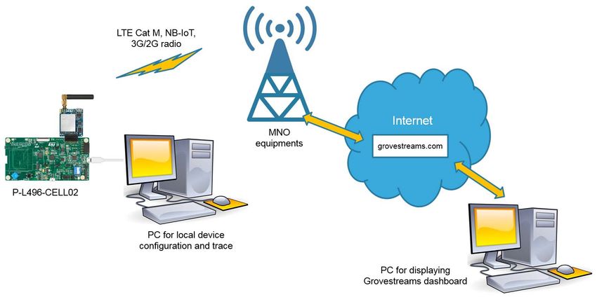
UM2426                                                                                                                              Contents

                        7.3.1       Console command activation . . . . . . . . . . . . . . . . . . . . . . . . . . . . . . . . . 33

8              How to customize the software? . . . . . . . . . . . . . . . . . . . . . . . . . . . . . . 34
               8.1      First customization level: user customization . . . . . . . . . . . . . . . . . . . . . . 34
               8.2      Second customization level: advanced user customization . . . . . . . . . . . 34
                        8.2.1       Adding/removing an application in firmware . . . . . . . . . . . . . . . . . . . . . 34
                        8.2.2       IP stack on MCU side or on modem side . . . . . . . . . . . . . . . . . . . . . . . 35
                        8.2.3       Different kinds of available traces . . . . . . . . . . . . . . . . . . . . . . . . . . . . . 36
                        8.2.4       How to configure traces? . . . . . . . . . . . . . . . . . . . . . . . . . . . . . . . . . . . . 37
               8.3      Third customization level: developer customization . . . . . . . . . . . . . . . . . 37
                        8.3.1       Boot . . . . . . . . . . . . . . . . . . . . . . . . . . . . . . . . . . . . . . . . . . . . . . . . . . . . 37
                        8.3.2       Initialization of software components . . . . . . . . . . . . . . . . . . . . . . . . . . . 37
                        8.3.3       Software customization . . . . . . . . . . . . . . . . . . . . . . . . . . . . . . . . . . . . . 38
                        8.3.4       Firmware adaptation to a new HW configuration . . . . . . . . . . . . . . . . . . 38
                        8.3.5       Adding a new component . . . . . . . . . . . . . . . . . . . . . . . . . . . . . . . . . . . 38
               8.4      Data cache . . . . . . . . . . . . . . . . . . . . . . . . . . . . . . . . . . . . . . . . . . . . . . . . 39
                        8.4.1       Introduction . . . . . . . . . . . . . . . . . . . . . . . . . . . . . . . . . . . . . . . . . . . . . . 39
                        8.4.2       Data Cache API . . . . . . . . . . . . . . . . . . . . . . . . . . . . . . . . . . . . . . . . . . . 39
                        8.4.3       Main Data Cache entries . . . . . . . . . . . . . . . . . . . . . . . . . . . . . . . . . . . . 40
               8.5      Thread stack consumption monitoring . . . . . . . . . . . . . . . . . . . . . . . . . . . 41

Appendix A Support material . . . . . . . . . . . . . . . . . . . . . . . . . . . . . . . . . . . . . . . . 43
               A.1      How to configure a Grovestreams account? . . . . . . . . . . . . . . . . . . . . . . . 43
               A.2      How to activate the soldered SIM card? . . . . . . . . . . . . . . . . . . . . . . . . . . 45
               A.3      How to measure cellular throughput? . . . . . . . . . . . . . . . . . . . . . . . . . . . . 47
                        A.3.1       Introduction . . . . . . . . . . . . . . . . . . . . . . . . . . . . . . . . . . . . . . . . . . . . . . . 47
                        A.3.2       Preparation of the measurements. . . . . . . . . . . . . . . . . . . . . . . . . . . . . . 47
                        A.3.3       Example . . . . . . . . . . . . . . . . . . . . . . . . . . . . . . . . . . . . . . . . . . . . . . . . . 48
               A.4      How to select BG96 modem configuration bands? . . . . . . . . . . . . . . . . . . 48

Revision history . . . . . . . . . . . . . . . . . . . . . . . . . . . . . . . . . . . . . . . . . . . . . . . . . . . . 49

                                                          UM2426 Rev 4                                                                      3/51
                                                                                                                                                      3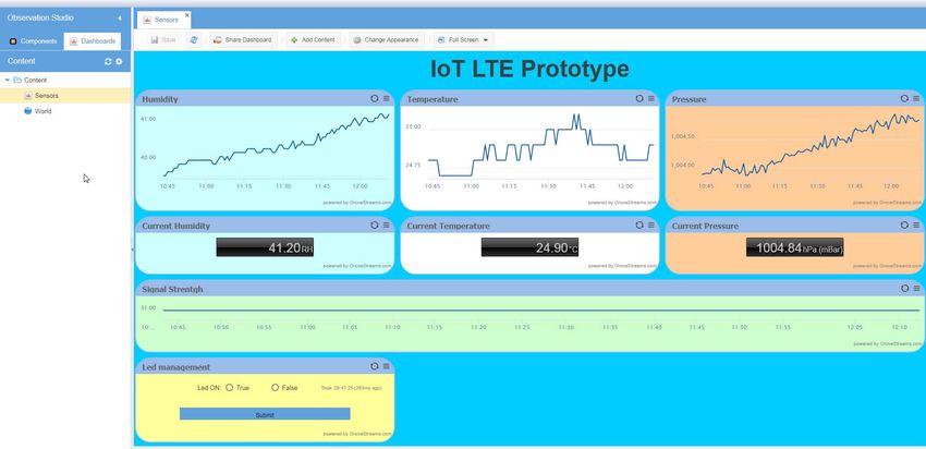
List of tables                                                                                                                       UM2426

List of tables

Table 1.    List of acronyms . . . . . . . . . . . . . . . . . . . . . . . . . . . . . . . . . . . . . . . . . . . . . . . . . . . . . . . . . . 7
Table 2.    Compilation variables for applications in firmware . . . . . . . . . . . . . . . . . . . . . . . . . . . . . . . 34
Table 3.    Compilation variable for IP stack selection . . . . . . . . . . . . . . . . . . . . . . . . . . . . . . . . . . . . . 36
Table 4.    New thread registration example . . . . . . . . . . . . . . . . . . . . . . . . . . . . . . . . . . . . . . . . . . . . 41
Table 5.    Number of project threads setting example . . . . . . . . . . . . . . . . . . . . . . . . . . . . . . . . . . . . 42
Table 6.    Code for thread stack consumption monitoring . . . . . . . . . . . . . . . . . . . . . . . . . . . . . . . . . 42
Table 7.    Document revision history . . . . . . . . . . . . . . . . . . . . . . . . . . . . . . . . . . . . . . . . . . . . . . . . . 49

4/51                                                       UM2426 Rev 4
UM2426                                                                                                                    List of figures

List of figures

Figure 1.    Cellular IoT connectivity . . . . . . . . . . . . . . . . . . . . . . . . . . . . . . . . . . . . . . . . . . . . . . . . . . . 10
Figure 2.    Architecture concept . . . . . . . . . . . . . . . . . . . . . . . . . . . . . . . . . . . . . . . . . . . . . . . . . . . . . . 12
Figure 3.    Static architecture view . . . . . . . . . . . . . . . . . . . . . . . . . . . . . . . . . . . . . . . . . . . . . . . . . . . . 14
Figure 4.    Dynamic architecture - Platform initialization and start . . . . . . . . . . . . . . . . . . . . . . . . . . . . 17
Figure 5.    Dynamic architecture - Up to PDN creation . . . . . . . . . . . . . . . . . . . . . . . . . . . . . . . . . . . . 18
Figure 6.    Dynamic architecture - Socket . . . . . . . . . . . . . . . . . . . . . . . . . . . . . . . . . . . . . . . . . . . . . . 19
Figure 7.    X-CUBE-CELLULAR folder structure . . . . . . . . . . . . . . . . . . . . . . . . . . . . . . . . . . . . . . . . . 21
Figure 8.    X-CUBE-CELLULAR middleware folder structure . . . . . . . . . . . . . . . . . . . . . . . . . . . . . . . 22
Figure 9.    Grovestreams connection overview . . . . . . . . . . . . . . . . . . . . . . . . . . . . . . . . . . . . . . . . . . 23
Figure 10.   Grovestreams web interface, component view . . . . . . . . . . . . . . . . . . . . . . . . . . . . . . . . . . 26
Figure 11.   Grovestreams web interface, dashboard view . . . . . . . . . . . . . . . . . . . . . . . . . . . . . . . . . . 26
Figure 12.   Hardware setup (P-L496G-CELL02 example) . . . . . . . . . . . . . . . . . . . . . . . . . . . . . . . . . . 28
Figure 13.   Hardware view (P-L496G-CELL02 example) . . . . . . . . . . . . . . . . . . . . . . . . . . . . . . . . . . . 29
Figure 14.   Hardware view (“Discovery IoT node cellular with BG96” set example) . . . . . . . . . . . . . . . 30
Figure 15.   Serial port settings to interact with the host board . . . . . . . . . . . . . . . . . . . . . . . . . . . . . . . 32
Figure 16.   Serial port settings to interact with the host board (new-line) . . . . . . . . . . . . . . . . . . . . . . . 32
Figure 17.   Grovestreams organization creation acceptance screen . . . . . . . . . . . . . . . . . . . . . . . . . . 43
Figure 18.   Grovestreams organization creation screen . . . . . . . . . . . . . . . . . . . . . . . . . . . . . . . . . . . . 43
Figure 19.   Grovestreams organization access screen. . . . . . . . . . . . . . . . . . . . . . . . . . . . . . . . . . . . . 44
Figure 20.   Grovestreams organization administration menu . . . . . . . . . . . . . . . . . . . . . . . . . . . . . . . . 44
Figure 21.   Grovestreams API key selection screen . . . . . . . . . . . . . . . . . . . . . . . . . . . . . . . . . . . . . . . 45
Figure 22.   Grovestreams API key display screen . . . . . . . . . . . . . . . . . . . . . . . . . . . . . . . . . . . . . . . . 45

                                                           UM2426 Rev 4                                                                   5/51
                                                                                                                                                   5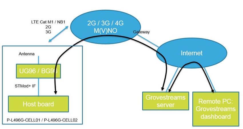
General information                                                                              UM2426

1          General information

           This user manual describes the X-CUBE-CELLULAR Expansion Package and its use. It
           explains neither the cellular networks nor the cellular protocol stacks, the descriptions of
           which being available on the Internet.
           The main features of the X-CUBE-CELLULAR Expansion Package are:
           •    Ready-to-run firmware examples using the 2G, 3G, LTE Cat M1, or NB-IoT protocols to
                support quick evaluation and development of IoT cloud applications
           •    Menu and command line through Virtual COM UART over USB ST-LINK to configure
                the connection to the Grovestreams cloud IoT platform (HTTP), and cellular
                connectivity (technology selection, bands, APN, and others)
           •    Cellular connection
           •    Reporting of such values as temperature, humidity, and pressure. The values are real if
                the MEMS add-on board (X-NUCLEO-IKS01A2) is connected, otherwise they are
                simulated. The sensors in the “Discovery IoT node cellular” set are always used
           •    Network radio level reporting
           •    Command line and application to test the access to a remote machine (ping command)
           •    Echo application to provide an example of connection and data exchanges using the
                TCP or UDP (connected or not-connected mode) socket protocols
           X-CUBE-CELLULAR is available for the following hardware:
           •    both the P-L496G-CELL01 and P-L496G-CELL02 cellular-to-cloud packs. Each pack is
                composed of an STM32L496AG-based Discovery host board connected to an add-on
                cellular modem through the STMod+ connector:
                –     The add-on board of P-L496G-CELL01 is equipped with the UG96 modem
                      (2G / 3G).
                –     The add-on board of P-L496G-CELL02 is equipped with the BG96 modem (LTE
                      Cat M / NB-IoT / 2G fallback).
           •    the “Discovery IoT node cellular” set, which is a combination of the B-L475E-IOT01A
                IoT Discovery board, X-NUCLEO-STMODA1 Arduino™ / STMod+ adapter, and:
                –     either STMicroelectronics MB1329 modem board with the BG96 modem
                –     or Sequans® GM01Q-STMOD modem board with the GM01Q modem (referenced
                      as B-CELL-GM01Q in STMicroelectronics)
           •    32L496GDISCOVERY Discovery board connected to the GM01Q-STMOD, UG96, or
                BG96 modem board
           Refer to the X-CUBE-CELLULAR cellular connectivity Expansion Package porting on other
           hardware application note (AN5249) for adaptation to other hardware such as the
           “Discovery IoT node cellular” set.

1.1        Terms and definitions
           Table 1 presents the definition of acronyms that are relevant for a better understanding of
           this document.

6/51                                         UM2426 Rev 4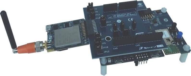
UM2426                                                                         General information

                                   Table 1. List of acronyms
                   Term                                       Definition

         API              Application programming interface
         APN              Access point name
         BSD              Berkeley software distribution
         BSP              Board support package
         C2C              Cellular to cloud
         CID              Context ID (context identifier of a cellular connection)
         COM              Cellular communication
         DC               Data Cache
         eUICC            Embedded UICC (UICC with remote profile feature)
         eSIM             Embedded SIM
         FEEPROM          Represents the embedded Flash memory of the STM32 MCU
         HAL              Hardware abstraction layer
         HTTP             Hypertext transfer protocol
         ICMP             Internet message control protocol
         IDE              Integrated development environment
         IF               Interface
         IoT              Internet of things (refer to [4])
         IPC              Inter-processor channel
         ITM              Instruction trace module
         LED              Light-emitting diode
         M2M              Machine to machine
         NAT              Network address translation
         NFMC             Network-friendly management configuration (refer to [4])
         NIFMAN           Network IF manager
         MNO              Mobile network operator
         MVNO             Mobile virtual operator
         PDN              Packet data network
         PDU              Protocol data unit
         PLMN             Public land mobile network
         PPP              Point-to-point protocol
         PPPoSIF          PPP over serial IF
         PS               Packet switching
         RAM              Random-access memory
         ROM              Read-only memory
         RSSI             Received-signal strength indication

                                      UM2426 Rev 4                                            7/51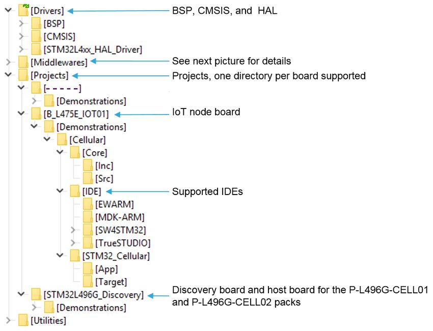
General information                                                                                            UM2426

                                           Table 1. List of acronyms (continued)
                      Term                                                  Definition

           RTC                           Real-time clock
           SMS                           Short-message service
           TCP                           Transmission control protocol
           UDP                           User datagram protocol
           UICC                          Universal integrated circuit card (also referred to as SIM card)
           URC                           Unsolicited result code

           The X-CUBE-CELLULAR Expansion Package runs on STM32L4 32-bit microcontrollers
           based on the Arm®(a) Cortex®-M4 processor.

1.2        References
           1.    Development guidelines for STM32Cube Expansion Packages user manual (UM2285)
           2.    Development checklist for STM32Cube Expansion Packages user manual (UM2312)
           3.    Getting started with STM32CubeL4 for STM32L4 Series and STM32L4+ Series user
                 manual (UM1860)
           4.    IoT Device Connection Efficiency Guidelines (TSG.34/TS.34) from the GSM
                 Association
           5.    X-CUBE-CELLULAR cellular connectivity Expansion Package porting on other
                 hardware application note (AN5249)

           a. Arm is a registered trademark of Arm Limited (or its subsidiaries) in the US and/or elsewhere.

8/51                                               UM2426 Rev 4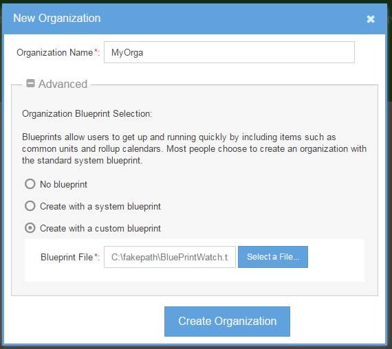
UM2426                                                       Important note regarding the security

2          Important note regarding the security

Caution:   Application developers must take care of security aspects, and put mechanisms in place to
           protect the tokens and secrets used for the connections.
           The application example provided in the X-CUBE-CELLULAR Expansion Package does not
           implement such protection mechanisms. It only presents a basic implementation for an easy
           understanding of the stack interface.

                 Warning:    Use the HW only with the antenna connected. With no
                             antenna connected, there is a risk of damage to the modem
                             because of the power reflected from the antenna connector
                             to the modem RF output.

                                          UM2426 Rev 4                                          9/51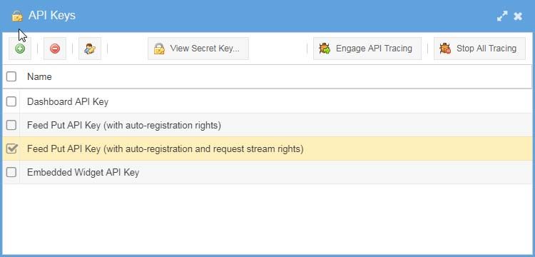
Service connectivity description UM2426
3 Service connectivity description
The X-CUBE-CELLULAR Expansion Package offers out-of-the-box connectivity for
communication to the Internet through the HTTP protocol. It implements a complete
middleware- and application-level stack in C language, which allows the connection of the
C2C kit to a web site.
The first connectivity example provided connects to the Grovestreams web site. In this
example, the board reports notifications to the Grovestreams web browser.
The second example provided implements the ping network-testing feature.
The third example provided is the echo application. The application connects or not to the
remote server (according to the socket protocol used), sends a buffer, and expects in return
the same buffer as the response.
Figure 1 presents the cellular IoT connectivity handled by the X-CUBE-CELLULAR
Expansion Package.
Figure 1. Cellular IoT connectivity
&ORXGSURYLGHU
$FFHVVQHWZRUNLQWHUIDFH ,QWHUQHWLQWHUIDFH
LQWHUIDFH
H1RGH% *33 *URYHVWUHDPV
3/
*&(// 1$7
%76 FRUH ,QWHUQHW +773
3/
*&(// 931
%6& QHWZRUN VHUYHU
,QWHUQHW
&XVWRPHUSUHPLVHV GRPDLQ 6HUYLFHSURYLGHU
2SHUDWRUHTXLSPHQW
HTXLSPHQW VHUYHUV HTXLSPHQW
06Y9
The P-L496G-CELL01 and P-L496G-CELL02 are used to represent all the compliant hardware.
The cellular-to-cloud kit comprises an STM32-based main board, a cellular add-on modem
board, and a prepaid SIM, which enables the registration to a cellular PLMN. The global
roaming provided by the SIM provider allows device attachment from any country. The SIM
only offers IP connectivity (meaning that SMS is not supported). The volume of data
available in the prepaid offer depends on where it is used.
A private IP address is allocated to the device by the MNO or MVNO. Any client application
running on device using TCP transaction request/response can reach a server located in
the Internet by means of IP address translation (NAT) on the MNO/MVNO router.
10/51 UM2426 Rev 4UM2426 Package description
4 Package description
This chapter details the content and use of the X-CUBE-CELLULAR Expansion Package.
4.1 General description
The X-CUBE-CELLULAR Expansion Package only provides software components running
on the host STM32 MCU. Cellular modem firmware is not in the scope of this document.
The following integrated development environments are supported:
• IAR Embedded Workbench® for Arm® (EWARM)
• Keil® Microcontroller Development Kit (MDK-ARM)
• System Workbench for STM32 (referred to as SW4STM32)
Note: Refer to the release note available in the root folder of the delivery package for information
about the IDE versions supported.
IAR™ binaries are provided in the package.
4.2 Modem socket versus LwIP
Either modem socket or LwIP can be used for the IP stack:
• Modem socket: the IP stack runs in modem FW
• LwIP: the LwIP stack runs on the STM32 side
This option is selected through a flag that is used during the compilation process. The
generated FW is either for modem socket or for LwIP use. It is not possible to further
change this setting through the boot menu.
Note: If the modem socket is used, the software described in this user manual limits data plane
support to TCP or UDP IPv4 Client application only. TCP or UDP server modes are not
supported.
If LwIP is used, TCP and UDP (both server and client) are fully supported.
If LwIP is selected, the communication between host and modem is done through the PPP
layer. There is a PPP client on the host side, and a PPP server on the modem side.
PPPoSIF adapts the LwIP stack to a serial IF, while LwIP usually uses Ethernet interfacing.
Note: The LwIP mode is not supported for the “Discovery IoT node cellular” set.
4.3 Architecture
X-CUBE-CELLULAR runs on STM32 boards and allows sending or receiving IP packets to
or from the Internet via an add-on cellular module.
Note: Some parts of X-CUBE-CELLULAR can be used in a bare OS environment. The complete
stack only runs with FreeRTOS™.
UM2426 Rev 4 11/51Package description UM2426
The package is split into the following components:
• STM32L4 Series HAL
• CMSIS/FreeRTOS™
• LwIP
• AT Service
• Cellular Service
• Data_Cache
• IPC
• NIFMAN
• Com
• Cellular_Mngt
• Utilities
4.3.1 Architecture concept
This section provides a high-level view of the software architecture supporting cellular
connectivity, which is illustrated in Figure 2.
Figure 2. Architecture concept
$SSOLFDWLRQ
'DWDSODQHLQWHUIDFH &RQWUROSODQHLQWHUIDFH
&RPOLEUDU\ &HOOXODUB0QJWOLEUDU\ 'DWDB&DFKHOLEUDU\
/Z,3WDVN
1,)0$1
333R6,)WDVN &HOOXODU6HUYLFHWDVN
26&HOOXODUOLEUDU\&HOOXODU6HUYLFH$7IUDPHZRUN
$7&RUHWDVN
,3&
06Y9
12/51 UM2426 Rev 4UM2426 Package description
The cellular connectivity stack exposes two main interfaces to the application:
• The control plane interface: there are two interfaces for control. The cellular init library
provides an API to initialize SW components and starts the Cellular Service. The Data
Cache interface is used to read information related to cellular network like Signal
Strength. (RSSI), and to get event notification like network registration state changes
and network interface readiness.
• The data plane interface: also referred to as the Com interface, it is used to send and
receive TCP or UDP segments to and from a remote client or server. The interface is
based on standard BSD socket API in order to ease the integration of the application.
The IPC layer abstracts the actual HW bus interface used with the modem. The IPC
supports two logical channels, each composed of one Tx (to the IPC) and one Rx (from the
IPC). One is used for exchanging AT commands with the modem while the other one is
used to carry PPP frames when LwIP is used. The selection of the active channel is
controlled by Cellular Service.
UM2426 Rev 4 13/51Package description UM2426
4.3.2 Static architecture view
X-CUBE-CELLULAR static architecture is presented in Figure 3.
Figure 3. Static architecture view
$SSOLFDWLRQV
+773FOLHQW 3,1*FOLHQW (&+2FOLHQW
3& &RQQHFWLYLW\6HUYLFHOD\HU
VRIWZDUH ;&8%(&(//8/$5$3,
'DWDB&DFKH &RP &HOOXODUB0QJW
&06,6
&6+/$3,
&HOOXODU
6HUYLFH &HOOXODU6HUYLFHWDVN
8WLOLWLHV
&6//$3, 1,)0$1
/Z,3
)UHH5726 26OLEUDU\&HOOXODU6HUYLFHOLEUDU\
1HW,) 333
$7&RUH
0RGHP
333R6L) V\VWHP
333FOLHQWWDVN FRQWURO
$7 $7FXVWRP
6HUYLFH
0LGGOHZDUH
,3&
+DUGZDUHDEVWUDFWLRQOD\HU
'ULYHUV
'HYHORSPHQWERDUGV
06Y9
• HTTP client: implements an HTTP client, which sends requests to the
www.grovestreams.com cloud in the application. The HTTP client uses the Data Cache
to monitor the network interface state changes (from NIFMAN), and the COM socket
interface to send or receive HTTP packets over TCP. The HTTP client also implements
recovery as defined by GSMA TS 34 when a remote HTTP server is not reachable.
• ECHO client: implements a client application, which sends data to a remote server and
waits in return the same packet. It is used to provide a simple example using the TCP
or UDP protocol socket.
• PING client: implements a ping application that tests the access to a remote machine.
14/51 UM2426 Rev 4UM2426 Package description
• Connectivity Service layer:
– Data_Cache: framework that decouples the management of producer and
consumer data (resource). Any resource state updated by a producer is pushed to
the Data Cache (in RAM), which in turn informs the final consumer(s) to process
the updated resource state via the callback provided by the consumer application.
Data Cache is used by Cellular Service tasks to publish the Cellular network
information like RSSI. It is also used by NIFMAN to publish the network interface
readiness.
– Com: a library that provides a collection of BSD-like socket functions to open,
configure, and send or receive application PDU to remote TCP or UDP
applications. A high-level ping service is also provided.
– Cellular_Mngt library: exposes a basic function to initialize and start Cellular
Service components.
• PPP client task / PPPoSIF: optional component. It is only present when LwIP is used.
It is in charge of establishing the PPP link with the modem.
• LwIP / Net IF: the LwIP component and its adaptation to PPP.
• Cellular Service:
– Cellular Service task controls modem power-on and initialization, instructs the
modem to perform network registration, activates the PDN (PDP context), and
enters data transfer mode. It informs NIFMAN to setup the network interface (PPP
link). It uses AT service to send AT commands to the modem.
It implements a generic finite state machine to maintain consistent service state
based on modem internal state change events (such as FOTA or reset), network
registration state change events, and events related to the and PDP context
status. It implements the network friendly features (NFMC) as defined in [4]. For
example, when PDP activation fails because of a wrong APN, the Cellular Service
task performs a new attempt after expiration of a back-off timer.
The Cellular Service task stores the cellular configuration and network access
parameters into the Flash memory, and configure the modem as per need. The
configuration for example encompasses APN and CID settings, enabling and
disabling NFMC, and setting the back-off timers.
For system robustness, the Cellular Service task ensures that the modem is
always operational by regularly polling the modem RSSI.
– Cellular Service OS: is a library that offers a collection of functions to low-level
Cellular Service. The library serializes the access to the single AT channel
interface that is used to communicate with the modem. The functions are called by
the COM service and the Cellular Service task.
– Cellular Service library: offers a collection of blocking function calls to interact
with a modem. Cellular Service is in charge of translating the request from the
Cellular Service task or COM service to a sequence of AT commands that must be
sent to the modem. It finally calls a callback function (from the Cellular Service
task or COM service) when an asynchronous event (URC) is received from the
modem.
– AT Service: provides a framework to send or receive AT commands to or from the
modem over IPC. The AT Core task is in charge of processing the Cellular Service
requests and translate them into AT commands. It is also in charge of processing
UM2426 Rev 4 15/51Package description UM2426
AT commands response and URCs from the modem and forward them to Cellular
Service. AT is split into two parts:
1. a generic part, "Core" (AT framework and manage standard AT commands)
2. a specific part, "custom" (implements specific modem behavior and AT
commands)
– Modem system control: support modem HW system control signaling (power
on/off, reset). It is split into a generic and a specific part. The generic part exposes
the generic API to the application (Cellular Service) while the specific part controls
the GPIO dedicated to the modem.
• NIFMAN: the network interface manager task controls network interface activation.
When LwIP is used, NIFMAN monitors the PPP server status (on the modem side), and
starts or stops the PPP client accordingly. The application can then monitor the network
interface status before opening a socket for data transfer.
• IPC: abstracts the actual physical interface (UART) to the upper layer. Supports the
logical channel handler (FIFO) that is mapped to a physical channel. Supports two
channels: character mode and stream mode:
– Stream mode is used for data transfer (PPP).
– Character mode is used to send AT commands.
• Utilities: provides tools such as debug and trace. Also provides the setup menu (over
any terminal through a serial interface) to change the default configuration, which is
hard coded during compilation and image creation.
• FreeRTOS™ (and CMSIS): provides RTOS services to create the resources and
scheduler needed by the software to run, such as threads and tasks, dynamic memory
allocation, mutexes, and semaphores. A default task (freertos.c) is in charge of system
initialization, creation of all application tasks. It finally initializes and starts the Cellular
Service components by calling cellular_init() and cellular_start().
4.3.3 Dynamic architecture view
The X-CUBE-CELLULAR dynamic architecture is further illustrated with diagram sequences
that illustrate the interactions between components from initialization to socket:
• Figure 4: Dynamic architecture - Platform initialization and start
• Figure 5: Dynamic architecture - Up to PDN creation
• Figure 6: Dynamic architecture - Socket
16/51 UM2426 Rev 4Figure 4. Dynamic architecture - Platform initialization and start
UM2426
DSS! 'HIDXOW &HOOXODUB6HUYLFH
&RP 'DWDB&DFKH &HOOXODUB0QJW
WDVN WDVN WDVN
FHOOXODUBLQLW
,QLWLDOL]HVWKH&RPVRFNHWGHVFULSWRUWDEOHV
,QLWLDOL]HVWKH&HOOXODU6:UHVRXUFHV
VXFKDVPXWH[GHIDXOWVHWWLQJVYDOXHVDQGRWKHUV
,QLWLDOL]HVWKHFHOOXODUGDWDFDFKHVFRQWHQW
,QLWLDOL]HVWKHQHWZRUNLQWHUIDFHPDQDJHU
DSS!BLQLW
FHOOXODUBVWDUW
UM2426 Rev 4
&RQILJXUHVWKH&HOOXODU6HUYLFHVHWWLQJV
6,0FDUGVORW566,SROOLQJSHULRG1HWZRUNUHJLVWUDWLRQ
WLPHU3'1DFWLYDWLRQUHWU\WLPHUV 1)0&
0RGHP')27$PRQLWRULQJWLPHU
6WDUWVWKH&HOOXODU6HUYLFHWDVN
6WDUWVWKHUDGLRLQWHUIDFHDQGWDVNVFUHDWLRQ
DSS!BVWDUW
GFBFRPBUHJLVWHUBJHQBHYHQWBFE DSSBFDOOEDFN
5HJLVWHUDSSOLFDWLRQFDOOEDFNIXQFWLRQ
/HJHQG
)XQFWLRQFDOO
)XQFWLRQUHWXUQ
Package description
17/51Figure 5. Dynamic architecture - Up to PDN creation
18/51
Package description
DSS! 'HIDXOW &HOOXODUB6HUYLFH
&RP 'DWDB&DFKH &HOOXODUB0QJW
WDVN WDVN WDVN
2QFHVWDUWHGWKH&HOOXODU6HUYLFHWDVNSHUIRUPVDFWLRQVWRSRZHUWKHPRGHPDQGDQ\
DFWLRQWRUHJLVWHUWR1HWZRUNDQGDFWLYDWH3'1
GFBFRPBZULWH 5$',2B/7(B,1)2
21
DSSBFDOOEDFN HYHQWBLG '&B&20B5$',2B/7(B,1)2
&KHFNVWKH6,03,1FRGH
UHDGV,06,DQGRWKHUVLQIRUPDWLRQ
GFBFRPBZULWH 6,0B,1)2
,06,
DSSBFDOOEDFN HYHQWBLG '&B&20B6,0B,1)2
UM2426 Rev 4
2QFHWKHPRGHPLVLQLWLDOL]HG&67IRUFHVWKHPRGHPWRSHUIRUP³DXWRPDWLF´1HWZRUN
VHDUFKDQGPRQLWRUWKHVLJQDOVWUHQJWK,IWKHVLJQDOTXDOLW\LVJRRGHQRXJKLWSHUIRUPV
QHWZRUNUHJLVWUDWLRQIRU&6DQG36GRPDLQVDQGILQDOO\DFWLYDWHVWKH3'1
GFBFRPBZULWH &(//8/$5B,1)2
566,
DSSBFDOOEDFN HYHQWBLG '&B&20B&(//8/$5
DSSBFDOOEDFN HYHQWBLG '&B&20B1,)0$1 :KHQ3'1LVUHDG\ ,3DGGDYDLODEOH &67LQIRUPV1,)0$1YLD'DWDB&DFKH
1,)0$1LQWXUQXSGDWHVWKH1HWZRUN,QWHUIDFH6WDWHWR21
GFBFRPBUHDG '&B&20B1,)0$1B,1)2
/HJHQG
)XQFWLRQFDOO
)XQFWLRQUHWXUQ
UM2426Figure 6. Dynamic architecture - Socket
UM2426
DSS! 'HIDXOW &HOOXODUB6HUYLFH
&RP 'DWDB&DFKH &HOOXODUB0QJW
WDVN WDVN WDVN
FRPBVRFNHW
FRPBELQG
2SWLRQDO
FRPBVHWVRFNRSW
2SWLRQDO
FRPBFRQQHFW
'HSHQGVRQWKHSURWRFROXVHG FRQQHFWHGRUQRW
UM2426 Rev 4
6HQGGDWD
FRPBVHQG
5HFHLYHGDWD
FRPBUHFY
FRPBFORVH
2SWLRQDO
/HJHQG
)XQFWLRQFDOO
Package description
)XQFWLRQUHWXUQ
19/51Package description UM2426
4.4 X-CUBE-CELLULAR Expansion Package description
This section describes the software components of the X-CUBE-CELLULAR package.
X-CUBE-CELLULAR is an Expansion Package for STM32Cube. Its main features are:
• Fully compliant with STM32Cube architecture
• Expands STM32Cube in order to enable the development of applications accessing
and using various cloud platforms
• Based on the STM32CubeHAL, which is the hardware abstraction layer for STM32
microcontrollers
The software components used by the application are:
• STM32Cube HAL
The HAL driver layer provides a generic multi-instance simple set of APIs (application
programming interfaces) to interact with the upper layers (application, libraries and
stacks).
It is composed of generic and extension APIs. It is directly built around a generic
architecture and allows the layers that are built upon, such as the middleware layer,
implementing their functionalities without dependencies on the specific hardware
configuration for a given microcontroller unit (MCU).
This structure improves the library code reusability and guarantees an easy portability
onto other devices.
• Board support package (BSP)
The software package needs to support the peripherals on the STM32 boards apart
from the MCU. This software is included in the board support package (BSP). This is a
limited set of APIs which provides a programming interface for certain board specific
peripherals such as the LED and the User button.
• Application
HTTP, ECHO, and PING clients.
• Middleware
Optionally LwIP.
• FreeRTOS™
FreeRTOS™ is mandatory to run the tasks for X-CUBE-CELLULAR components.
• Configuration files
component and platform configuration file are provided at project repository
– plf_features.h defines the feature list to include in firmware.
– plf_hw_config.h defines the mapping of the GPIO and HW interface specific to
logical names to ease SW porting to another board. It also provides the HW bus
interface configuration (such as the UART) used for communicating with the
modem.
– plf_sw_config.h provides platform SW configuration such as task priorities, trace,
stack size monitoring and others. It also provides application behaviors, which can
differ from one platform to another, such as modem polling timer value, button
configuration and polling and others.
– plf_stack_size.h defines the thread stack size.
Other parameters can be customized. Additional details are provided in Chapter 8: How to
customize the software? on page 34.
Some parameters can also be defined dynamically at runtime. They are stored in the Flash
memory and re-used at the next platform boot if needed.
20/51 UM2426 Rev 4UM2426 Package description
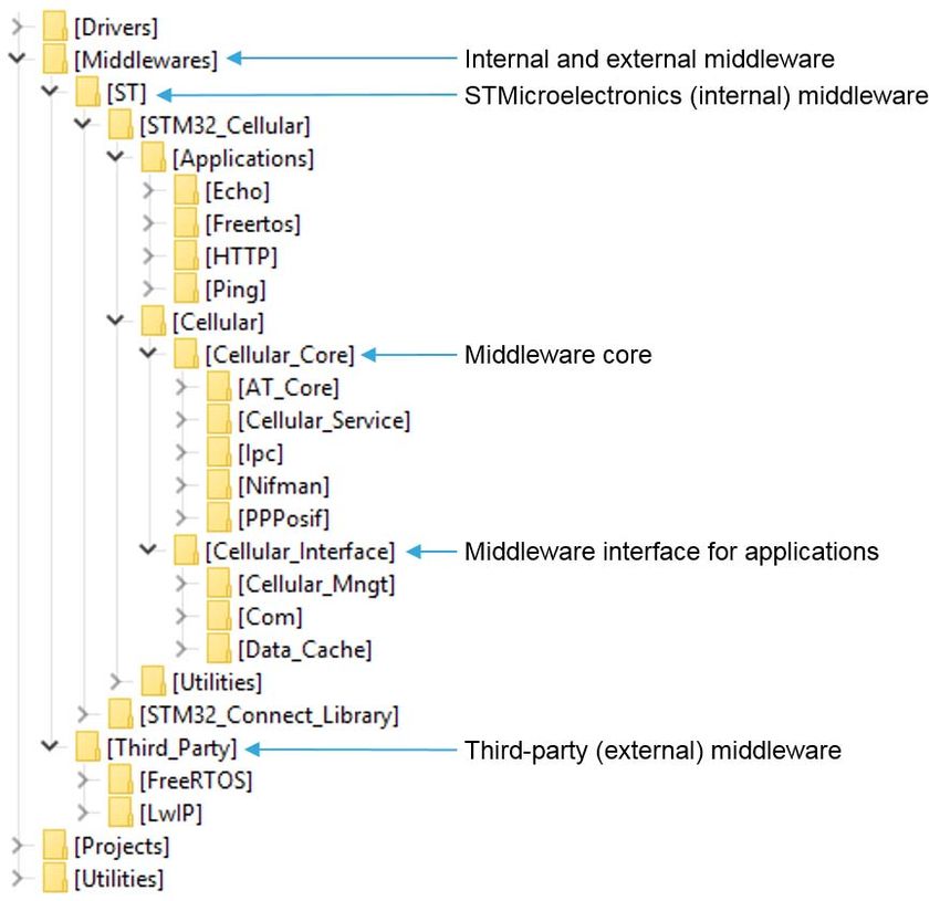
4.5 Folder structure
Figure 7 presents the global folder structure of the X-CUBE-CELLULAR Expansion
Package.
Figure 7. X-CUBE-CELLULAR folder structure
Figure 8 details the middleware folder structure of the X-CUBE-CELLULAR Expansion
Package.
UM2426 Rev 4 21/51Package description UM2426
Figure 8. X-CUBE-CELLULAR middleware folder structure
4.6 Reset push-button
The reset push-button (black) is used to reset the board at any time. This action forces the
reboot of the platform.
4.7 Real-time clock
System date and time are managed by the RTC. At boot time, it is updated by the HTTP
client application, which gets time and date from the Grovestreams server.
The system date can also be manually updated at boot setup.
The HAL_RTC_GetTime() function provides the time to the application.
Note: The hour value depends on the Grovestreams server time zone.
22/51 UM2426 Rev 4UM2426 Cellular connectivity examples
5 Cellular connectivity examples
This chapter describes the cellular connectivity available examples. Several examples that
can run in parallel are provided, such as PING, ECHO, and HTTP clients.
5.1 Real network or simulator
The worldwide coverage of 2G and 3G networks makes it possible to systematically run the
examples for these technologies on real networks. The LTE cat M1 and NB1 technologies
do not yet offer a similar global coverage. If such networks are not available, the user must
use a Cat M1 / NB1 compliant network simulator.
In this document, assumption is made that a real network is available whatever the network
technology used.
The add-on modem boards (in P-L496G-CELL01 and P-L496G-CELL02) embed an eSIM,
provisioned with the EMnify MVNO profile:
• For the UG96 modem, 2G or 3G real networks are used
• For the BG96 modem, with the EMnify eSIM, 2G fallback is possible and sometimes,
depending on the country, LTE Cat M1 is also available. To be sure to be able to use
the BG96 modem in Cat M1 or NB1 mode, the user must insert a plastic SIM card
compliant with this network technology from an MNO that has already deployed it.
5.2 Connection overview
The Grovestreams connection overview presented in Figure 9.
Figure 9. Grovestreams connection overview
The P-L496G-CELL01 and P-L496G-CELL02 are used to represent all the compliant hardware.
UM2426 Rev 4 23/51Cellular connectivity examples UM2426
5.3 PING example
The console command allows the generation of ping requests (refer to Section 7.3: Console
command on page 33). The simple ping command generates 10 ping requests using
default IP address 8.8.8.8. To specify another IP address, use the ping
command.
Ping command example:
ping 8.8.4.4
Ping result example:
>
>Ping: 32 bytes from 8.8.4.4: seq=01 time= 73ms
Ping: 32 bytes from 8.8.4.4: seq=02 time= 77ms
Ping: 32 bytes from 8.8.4.4: seq=03 time= 48ms
Ping: 32 bytes from 8.8.4.4: seq=04 time= 59ms
Ping: 32 bytes from 8.8.4.4: seq=05 time= 78ms
Ping: 32 bytes from 8.8.4.4: seq=06 time= 74ms
Ping: 32 bytes from 8.8.4.4: seq=07 time= 56ms
Ping: 32 bytes from 8.8.4.4: seq=08 time= 70ms
Ping: 32 bytes from 8.8.4.4: seq=09 time= 66ms
Ping: 32 bytes from 8.8.4.4: seq=10 time= 66ms
--- 8.8.4.4 Ping Statistics ---
Ping: min/avg/max = 48/66/78 ms ok = 10/10
>
24/51 UM2426 Rev 4UM2426 Cellular connectivity examples
5.4 ECHO example
The ECHO application is a client that exchanges data with a remote server using the TCP or
UDP (connected or not-connected mode) socket. ECHO is the only default example
provided in binaries:
• The default data exchanged with the server is the current “date and time”. The
response expected from the server is the exact same buffer (an echo).
– Format of the default data exchanged (size 21 bytes):
dd/mm/yyyy - hh:mm:ss
– Prompt command for changing the size of the data exchanged:
echoclient size
where n is the total data size (minimum size is 21 bytes)
In addition to the default data, a loop of numbers from 0 to 9 is used to reach the
expected size.
• The default protocol used to create the socket is UDP not-connected mode if the
modem supports this mode, or UDP connected otherwise.
The protocol used is changed with the prompt command
echoclient protocol
– = TCP: TCP
– = UDP: UDP connected mode protocol
– = UDPSERVICE: UDP not-connected mode protocol
(only proposed if the modem supports it)
Note: if the echo client is already active (exchange of data with a server) while the
echoclient protocol command is typed, the socket is closed before a new one is
created with the new protocol requested.
• The echo client application is activated with the command echoclient on.
• The echo client application is deactivated with the command echoclient off.
5.5 Grovestreams (HTTP) access example
The cellular connectivity demonstration for Grovestreams consists in two use cases:
• The device periodically reports sensor data to the Grovestreams cloud IoT platform.
The end-user connects to the Grovestreams web server dashboard.
• The end-user controls the LED application state from the dashboard.
The HTTP client on the MCU sets up a connection to the Grovestreams server through a
dedicated account. It pushes data (temperature, humidity, pressure and cellular radio signal
strength) to the Grovestreams server through the HTTP PUT command. An end-user
connected to the Grovestreams platform with a standard web browser has access to the
Grovestreams dashboard web page. The device polls the Grovestreams web server every
two seconds by sending HTTP GET commands to retrieve any request from the end-user.
By this mechanism, the end-user can switch the application LED on the host board ON and
OFF.
UM2426 Rev 4 25/51Cellular connectivity examples UM2426
For temperature, humidity, and pressure, if the X-NUCLEO-IKS01A2 board with sensors is
plugged, real values are sent to the cloud server. Otherwise, simulated data are reported.
With the “Discovery IoT node cellular” set, real values are always sent.
Figure 10 and Figure 11 present the related Grovestreams interfaces.
Figure 10. Grovestreams web interface, component view
Figure 11. Grovestreams web interface, dashboard view
26/51 UM2426 Rev 4UM2426 Hardware and software environment setup
6 Hardware and software environment setup
The STM32 MCU FW must be programmed, whatever the test at stake. Modem FW can be
upgraded too if needed.
Note: For P-L496G-CELL01 and P-L496G-CELL02, before programming with a new firmware,
connect the system to a PC with Tera Term and note the voucher number; this number is
needed to activate the eSIM on the modem board. If the board is flashed before getting the
voucher, re-flash the original image and get the voucher.
The embedded SIM in the “Discovery IoT node cellular” set is not provisoned with a M(V)NO
profile: No eSIM activation is needed; A plastic SIM card must be used instead.
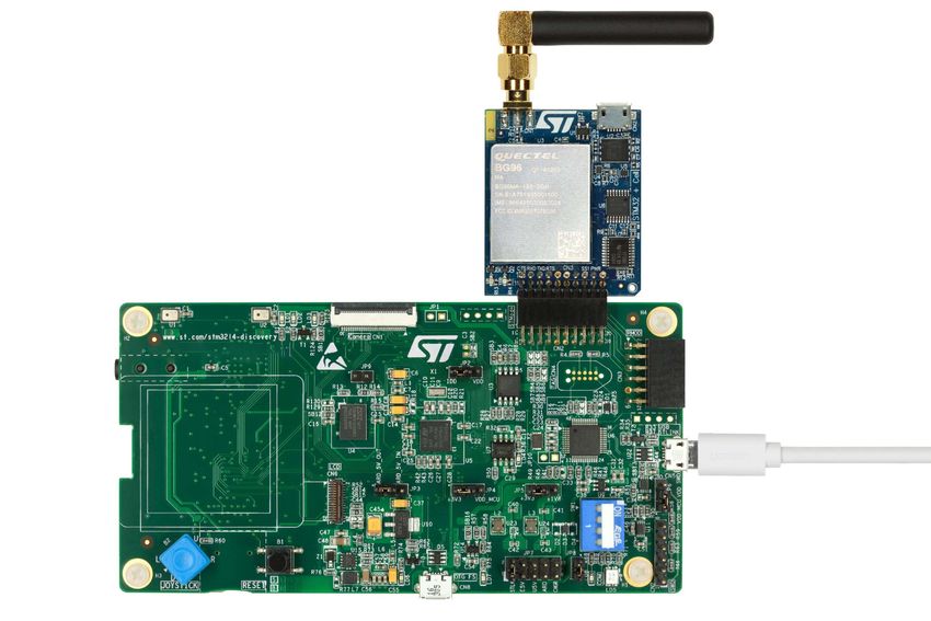
For the P-L496G-CELL01 and P-L496G-CELL02 Discovery packs, connect the host board
to the modem board by means of the STMod+ connector (refer to Figure 13). For the
“Discovery IoT node cellular” set, first connect the MB1329 modem board to the
X-NUCLEO-STMODA1 adapter board, then connect the X-NUCLEO-STMODA1 to the
B-L475E-IOT01A host board (refer to Figure 14).
The GM01Q-STMOD modem board can be connected by means of the STMod+ connector
either to the host board contained in P-L496G-CELL01 or P-L496G-CELL02, to the
32L496GDISCOVERY board, or to the B-L475E-IOT01A board through the X-NUCLEO-
STMODA1 adapter. For the first three possibilities, refer to Figure 13; for the last one, refer
to Figure 14.
When the UICC chip soldered on the add-on board is not used, insert a UICC compliant with
the real network used into the UICC socket.
If the soldered UICC chip is used, it must be activated beforehand and selected at boot by
means of the boot menu.
Power on the board by plugging its USB connector to a PC, USB power supply, or USB
power bank. If traces must be displayed, the USB connector must be connected to a PC
with an open console application.
Power bands are needed for instance when 2G is selected with particular radio conditions.
Warning: Use the HW only with the antenna connected. With no
antenna connected, there is a risk of damage to the modem
because of the power reflected from the antenna connector
to the modem RF output.
UM2426 Rev 4 27/51Hardware and software environment setup UM2426
Figure 12 depicts the hardware setup.
Figure 12. Hardware setup (P-L496G-CELL02 example)
28/51 UM2426 Rev 4UM2426 Hardware and software environment setup
Figure 13 shows the P-L496G-CELL02 with the USB cable in place for power supply and
optional trace / boot menu.
Figure 13. Hardware view (P-L496G-CELL02 example)
$SSOLFDWLRQ/(' 3OXJJHGDQWHQQD
86%
SRZHUDQGWUDFH
5HVHWSXVKEXWWRQ
06Y9
UM2426 Rev 4 29/51Hardware and software environment setup UM2426
Figure 14 shows the “Discovery IoT node cellular with BG96” set with the B-L475E-IOT01A
host, X-NUCLEO-STMODA1 adapter and MB1329 modem boards connected together.
Figure 14. Hardware view (“Discovery IoT node cellular with BG96” set example)
3ODVWLF6,0 0RGHPPRGXOH 5HVHW
FDUG %*
SXVKEXWWRQ
0RGHPERDUG
3OXJJHGDQWHQQD +RVWERDUG
$UGXLQR670RG 86%
DGDSWHU SRZHUDQGWUDFH
06Y
9
Summary of environment setup steps:
• Create the Grovestreams account (refer to A.1: How to configure a Grovestreams
account? on page 43)
• Create a Grovestreams organization in the Grovestreams account (refer to A.1)
• Get the 2 needed API keys in the organization (refer to A.1)
• Update the provided .txt file with the user API keys previously read
• Connect the modem add-on board with its antenna to the host STM32 board (refer to
Figure 13)
• Connect the STM32 board to a PC via a USB cable (refer to Figure 13)
• Program the STM32 board by dragging and dropping the STM32 FW image onto the
newly appeared drive
• Start the terminal and set the parameters (refer to Chapter 7: Interacting with the host
board)
• Reboot the board (press the black button)
• Select item "2" in the boot menu (refer to Chapter 7: Interacting with the host board for
a complete description), select the SIM card to be used and the APN if needed, set the
Grovestreams parameters, and save in Flash. The APN name is provided by the
M(V)NO.
30/51 UM2426 Rev 4UM2426 Hardware and software environment setup
• Reboot the board (the trace is displayed in the terminal)
• Connect to the Grovestreams account, select the dashboard, double click on sensor,
observe the data displayed and the toggling of the LED induced by the Grovestreams
dashboard.
There are 2 important txt files for Grovestreams:
• GS_ Blueprint.txt: used during organization creation (use as such, no modification is
needed)
• GS_setup.txt: used to configure the generic FW, to access the Grovestreams account.
This file must be updated with the 2 API keys replaced by the API keys of the
organization (refer to A.1: How to configure a Grovestreams account? on page 43)
Note: File “GS_setup.txt” is not mandatory. It is only an user-friendly method to enter personal
Grovestreams parameters into the FW, avoiding to enter each parameter individually by
using "File" > "Send file …" and selecting “GS_setup.txt”.
Refer to Chapter 7: Interacting with the host board for entering Grovestreams parameters
with file “GS_setup.txt” by using the menu at boot (Setup Menu > Grovestreams).
Refer to Chapter 7: Interacting with the host board for selecting the UICC or SIM socket,
and the APN, by using the menu at boot with (Setup Menu > Cellular Service).
UM2426 Rev 4 31/51Interacting with the host board UM2426
7 Interacting with the host board
To interact with the Host board a serial console is used (Virtual COM port over USB). With
the Windows® operating system, the use of the Tera Term software is recommended.
Serial port settings for communicating with the host board are illustrated in Figure 15. The
menu is reached through Setup > Serial port. Set Baud rate to 115200 to get Tera Term up
and running. For the boot setup configuration, a Transmit delay of 10 ms must be applied.
Local echo must be enabled.
Figure 15. Serial port settings to interact with the host board
Figure 16 illustrates the menu for setting the terminal parameters. It is reached through
Setup > Terminal. Set both Receive and Transmit New-line parameters to CR.
Figure 16. Serial port settings to interact with the host board (new-line)
32/51 UM2426 Rev 4UM2426 Interacting with the host board
Once all terminal and serial port parameters are properly set, press the board reset button
(black).
The HTTP service is active as soon as STM32 SW is running, sending data to the
Grovestreams cloud. The Grovestreams dashboard displays the data values and switches
the device LED ON / OFF.
Parameter setting is possible at boot time through the console. Refer to Section 7.2: Boot
menu for details.
7.1 Debug
The debug trace is viewed through the Virtual COM port of the PC that is connected to the
board and powers it.
Debug levels are customized in file plf_sw_config.h. Details are provided in Section 8.2.3:
Different kinds of available traces, Section 8.2.4: How to configure traces? and Section 8.5:
Thread stack consumption monitoring.
7.2 Boot menu
The boot menu is enabled by setting the USE_DEFAULT_SETUP variable to 0, which is the
default value, in configuration file
Projects\STM32L496G-Discovery\Common_Projects_Files\inc\plf_sw_config.h.
At boot stage, a menu is displayed via the serial console to select the firmware use:
• Launch configuration setup
• Modem boot only without starting firmware applications
If no character is entered after 3 seconds, firmware starts in normal mode.
7.3 Console command
After target boot, the commands presented in this section are available to get and set
software component status.
7.3.1 Console command activation
• To activate the console command feature, the USE_CMD_CONSOLE compilation
variable must set to 1 in file
Projects\STM32L496G-Discovery\Common_Projects_Files\inc\ plf_features.h.
#define USE_CMD_CONSOLE (1)
• The board must be connected to a serial console as described in the introduction of
Chapter 7: Interacting with the host board on page 32.
• Type after boot to display the help
UM2426 Rev 4 33/51How to customize the software? UM2426
8 How to customize the software?
There are three possible software customization levels applicable to X-CUBE-CELLULAR,
which are presented in this chapter: user customization, advanced user customization, and
developer customization. This chapter also presents how to monitor thread stack
consumption.
8.1 First customization level: user customization
The first customization level is the setup configuration at boot time (refer to Chapter 7:
Interacting with the host board on page 32).
At this level, firmware is not modified. No customization-induced compilation is needed.
8.2 Second customization level: advanced user customization
At this level, firmware configuration modification is possible. Specific features can be added
or removed and firmware configuration parameters can be modified as presented in
sections 8.2.1, 8.2.2, 8.2.3, and 8.2.4.
Customization-induced recompilation is needed.
8.2.1 Adding/removing an application in firmware
The Projects\STM32L496G-Discovery\Common_Projects_Files\inc\plf_features.h
configuration file allows the selection of the applications to be included in firmware.
Table 2 presents the compilation variables that can be defined or undefined as a function of
the applications needed.
Table 2. Compilation variables for applications in firmware
Compilation variable(1) Description
#define USE_HTTP_CLIENT Includes the HTTP client (Grovestreams) application.
Includes ping utilities. The ping application uses COM
PING API functionalities.
#define USE_PING_CLIENT If USE_PING_CLIENT is defined, USE_COM_PING must
be defined too (see the corresponding entry in this
table).
#define USE_ECHO_CLIENT Includes the ECHO client application.
Includes sensor management
Projects\Common\tests_utilities\dc_mems.c.
#define USE_DC_MEMS
Note: this option can be set only on
32L496GDISCOVERY.
Includes the simulation of sensors (no physical sensor
available)
#define USE_SIMU_MEMS Projects\Common\tests_utilities\dc_mems.c
This option can be used also with USE_DC_MEMS
defined. It is useful if no sensor shield is plugged.
34/51 UM2426 Rev 4UM2426 How to customize the software?
Table 2. Compilation variables for applications in firmware (continued)
Compilation variable(1) Description
Defines if the boot setup menu is used or not:
– 0: boot setup menu used
– 1: boot setup menu not used. In this case, default
parameters are set. These parameters are defined in
file config.h for each component using
#define USE_DEFAULT_SETUP
the setup menu
Projects\Applications\Cellular\radio_service\cellular\in
c\cellular_service_config.h
Projects\Common\applications\HTTP\inc\httpclient_co
nfig.h
Includes sensor emulation for Data Cache test
#define USE_DC_EMUL
Projects\Common\tests_utilities\dc_emul.c
Includes Data Cache test
#define USE_DC_TEST
Projects\Common\tests_utilities\dc_test.c
Includes ping functionalities in module COM.
Because few memory is used with PING functionalities,
this define provides the possibility not to include PING
#define USE_COM_PING
functions if PING is not used on platform.
If USE_PING_CLIENT is defined, then USE_COM_PING
has to be defined.
If activated, then when USE_SOCKETS_TYPE is set to
USE_SOCKETS_MODEM, com_getsockopt with
#define COM_SOCKETS_ERRNO_COMPAT COM_SO_ERROR parameter returns a value compatible
with errno.h (refer to file com_sockets_err_compat.c for
the conversion).
Includes console command
(refer to Section 7.3.1: Console command activation on
#define USE_CMD_CONSOLE
page 33 and Section A.3.2: Preparation of the
measurements on page 47).
Includes cellular throughput performance measurements
#define USE_CELPERF (refer to Section A.3.2: Preparation of the measurements
on page 47).
1. All defines are independent: several applications can be selected together.
8.2.2 IP stack on MCU side or on modem side
The IP stack runs either on the MCU side or on the modem side. The default configuration
is: modem side.
The Projects\STM32L496G-Discovery\Common_Projects_Files\inc\plf_feature.h
configuration file include allows the definition of the location of the IP stack used.
Table 3 presents the compilation variable that defines the IP stack used.
UM2426 Rev 4 35/51How to customize the software? UM2426
Table 3. Compilation variable for IP stack selection
Compilation variable Description
Defines the IP stack used:
– USE_SOCKETS_LWIP:
#define USE_SOCKETS_TYPE IP stack on the MCU side (LwIP stack)
– USE_SOCKETS_MODEM:
IP stack on the modem side(1)
1. If the IP stack used is on the modem side, only the TCP/UDP IPv4 Clients are supported.
8.2.3 Different kinds of available traces
Traces are centralized in the TraceInterface module.
C macros are defined in each module of X-CUBE-CELLULAR to manage the traces.
The user can easily modify or enrich the implementation according to his needs.
Enhanced UART traces
The traces are sent to the UART connected to the ST-Link, which uses the TraceInterface
module (for fine trace selection, pretty buffer display, and others).
This is the recommended trace option. It is activated by default.
ITM traces
The Instrumentation Trace Macrocell activates traces that are less intrusive than UART
traces. The TraceInterface module offers a basic implementation of ITM traces, which the
user can enrich according to his needs.
It is activated by default.
Note: Enhanced UART traces and ITM traces are activated by default and provide the same trace
at the same time on different communication channels.
To visualize the traces, the STM32 ST-Link Utility software must be installed.
The ITM trace is visualized after the following series of operation is performed:
1. Connect the USB ST-Link connector of the board to the computer
2. Connect the ST-Link Utility to the board (Menu Target>Connect)
3. Open the serial viewer (Menu STLINK>Printf via the SWO viewer)
4. Set the system clock to the correct value (usually 80 000 000 Hz)
5. Activate all stimulus ports
6. Press start to display the traces
Note: ST-Link Utility must be connected to the board. It is therefore not possible to debug via the
IDE and visualize the ITM trace at the same time.
Standard printf traces
It is possible to select standard printf traces instead of enhanced UART traces.
It uses also the UART connected to ST-Link but offer less options and buffers are not
displayed.
36/51 UM2426 Rev 4UM2426 How to customize the software?
8.2.4 How to configure traces?
The configuration of traces is done in file plf_sw_config.h by means of the following flags:
• SW_DEBUG_VERSION
– Set this flag to 1 (default value) to enable debug traces
– Set this flag to 0 to disable debug traces (only setup menu traces will be
displayed)
• TRACE_IF_TRACES_UART
– Set this flag to 1 to enable enhanced UART traces (default value)
– Set this flag to 0 to disable enhanced UART traces
• TRACE_IF_TRACES_ITM
– -Set this flag to 1 to enable ITM traces (default value)
– Set this flag to 0 to disable ITM traces
• USE_PRINTF
– Set this flag to 1 to enable standard printf UART traces
– Set this flag to 0 to disable standard printf UART traces (default value)
Note: When printf traces are activated, enhanced UART traces and ITM traces are disabled.
Each software module of X-CUBE-CELLULAR can be enabled or disabled using the
corresponding flag beginning by “USE_TRACE_”, such as USE_TRACE_HTTP_CLIENT or
USE_TRACE_PING_CLIENT for instance.
8.3 Third customization level: developer customization
8.3.1 Boot
The boot is the first part of the device initialization. It is included in file main.c (main
function). This part concerns the HW initialization done by HAL. The file is generated by
STM32CubeMX with the .ioc file provided. It must be updated only if a new HW is used or if
the user configures peripherals on the host board (such as GPIO, I2C, or others).
8.3.2 Initialization of software components
The SW components (application and middleware) are initialized in file freeRTOS.c. Each
component comprises a static initialization to initialize its data structure
(_Init), and a real time initialization to start the component thread
(_Start). Both are called from the StartDefaultTask function in the right
order.
UM2426 Rev 4 37/51How to customize the software? UM2426
8.3.3 Software customization
Firmware configuration parameters are included in files:
• FreeRTOSConfig.h: includes FreeRTOS™ parameters
• lwipopts.h: includes LwIP parameters
• plf_hw_config.h: includes HW parameters (such as UART configuration, GPIO
used, and others). A change is usually needed to adapt the
software to a new board.
• plf_sw_config.h: includes SW parameters (such as task priorities, trace
activations and others)
• plf_stack_size.h: includes thread stack sizes. The stack sizes included in this file
are used to calculate the FreeRTOS™ heap size (contained in
file FreeRTOSConfig.h).
• plf_features.h: includes the selected applications
8.3.4 Firmware adaptation to a new HW configuration
To adapt the firmware to a new board or new HW configuration, follow these steps:
1. Create an STM32CubeMX project based on the new board
2. Configure the HW IPs as configured for the 32L496GDISCOVERY board
3. Generate the software configuration files from STM32CubeMX
4. Update file plf_hw_config.h to match the GPIO and HW handler names generated in
the configuration files
8.3.5 Adding a new component
To add a new component (application or middleware), follow these steps:
1. Create an initialization function _Init to initialize the data structure of
the application
2. Create a starting function _Start to start a component thread
3. Add in the StartDefaultTask function (in file freertos.c) the call of
_Init and _Start
4. Add the stack priority constant in file plf_sw_config.h and the stack size in file
plf_stack_size.h. Other convenient configuration compilation variables can be added
as well.
5. Implement the component core. Each component owns at least one thread.
Interaction with the other components and whole system is done by using Data Cache.
Data Cache contains all system data to share between components (sensor values,
network state, … ). When a component updates a data in Data Cache, all subscribed
callback are called.
Generally a component subscribes a call back to Data Cache. The core of the
application thread waits for a Data Cache event and process it.
File httpclient.c can be used as example for the creation of a new application.
38/51 UM2426 Rev 4You can also read


