Unreal Engine 4 for Automation - Evgeny Pukki - Theseus
←
→
Page content transcription
If your browser does not render page correctly, please read the page content below
Evgeny Pukki

Unreal Engine 4 for Automation

Metropolia University of Applied Sciences
Bachelor of Engineering
Electrical and Automation Engineering
Bachelor’s Thesis
20.4.2021
Abstract

Author:                    Evgeny Pukki
Title:                     Unreal Engine 4 for Automation
Number of Pages:           36 pages + 6 appendices
Date:                      20 April 2021

Degree:                    Bachelor of Engineering
Degree Programme:          Electrical and Automation Engineering
Professional Major:        Automation Engineering
Instructors:               Timo Kasurinen, Senior Lecturer

The main purpose of this work was to create an algorithm for inverse kinematics
in the environment of the game engine Unreal Engine 4. This algorithm was
developed to control in real-time a spider robot, consisting of 12 servos, using
Unreal Engine 4.

Additional goals of this work were to consider the capabilities of the Unreal
Engine for creating procedural 3D animations. Examples of creating a
procedural 3D animation of the lidar operation and a 3D animation procedure
for a drone flight are considered in the thesis. This thesis also touches upon the
process of creating firmware for a 3D printer using Unreal Engine 4.

The developed algorithm is based on the algorithm of inverse kinematics
FABRIK and implemented with the help of integrated Unreal Engine 4 vector
calculation functions. The thesis discusses also the main stages of creating a
physical simulation of a spider robot.

The result of this work is a fully functional algorithm that has been tested to
control a real robot spider. The created inverse kinematics algorithm can be
modified to control any robot consisting of any number of servo motors where
inverse kinematics is required.

The developed firmware for 3D printer allows real-time control of 5 motor control
boards (ODRIVE V3.6 ) and 9 high-power brushless motors(D5065, 1800 W).

Keywords: game engine, unreal engine 4, real-time simulations, inverse
kinematics
Tiivistelmä

Tekija:                   Evgeny Pukki
Otsikko:                  Unreal Engine 4 Automaatioon
Sivumäärä:                36 sivua + 6 liitettä
Aika:                     20 Huhtikuuta 2021

Tutkinto:                 Bachelor of Engineering
Tutkinto-ohjelma:         Sähkö- ja automaatiotekniikka
Ammatillinen pääaine:     Automaatiotekniikkaa
Ohjaajat:                 Timo Kasurinen, Lehtori

Opinnäytetyön päätarkoitus oli luoda algoritmi käänteiselle kinematiikalle
pelimoottorin Unreal Engine 4 ympäristösä. Algoritmi on kehitetty ohjaamaan
reaaliajassa 12 servosta koostuvaa hämähäkkirobotia Unreal Engine 4:n avulla.
Tämän työn päätarkoitus oli luoda algoritmi käänteiselle kinematiikalle
pelimoottorin Unreal Engine 4 ympäristössä.

Algoritmi perustuu käänteisen kinematiikan FABRIK-algoritmiin ja se
toteutetaan integroitujen Unreal Engine 4 -vektorilaskutoimintojen avulla.
Opinnäytetyössä käsitellään myös hämähäkkirobotin fyysisen simulaation
luomisen päävaiheita Unreal Engine 4 -työkalujen avulla.

Työn tulos on täysin toimiva algoritmi, joka on testattu todellisen
robottihämähäkin hallitsemiseksi. Luotua käänteisen kinematiikan algoritmia
voidaan muokata ohjaamaan mitä tahansa robottia, joka koostuu mistä tahansa
servomoottoreista, jos tarvitaan käänteistä kinematiikkaa. 3D-tulostimen
laiteohjelmisto mahdollistaa reaaliaikaisen viiden moottorin ohjauskortin
(ODRIVE V3.6) ja yhdeksän suuritehoisen harjattoman moottorin (D5065, 1800
W) ohjaamisen.

Avainsanat:               pelimoottori, Unreal Engine 4, reaaliaikaiset
                          simulaatiot, käänteinen kinematiikka.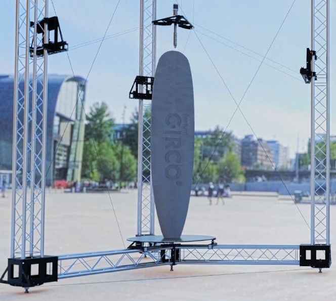
Contents

List of Abbreviations

1   Introduction                                                            1

2   Game Engine                                                             3

    2.1 The Operating Principle of a Game Engine                            3
         2.1.1 The Rendering Engine                                         4
         2.1.2 The Math Engine                                              5
         2.1.3 The Physics Engine                                           6
    2.2 Unreal Engine 4                                                     7

3   Creating Firmware and Real-time Simulation for a 3D Printer Using Unreal
    Engine 4                                                                 9

    3.1 Motors Control                                                      9
    3.2 Firmware Features                                                  10

4 Creation of Procedural Animation for Automation Systems Using Unreal
Engine 4                                                               11

    4.1 Lidar Procedural Animation                                         12
    4.2 Drone Procedural Animation                                         15

5   Creation of Inverse Kinematics Algorithm in the Unreal Engine 4
    Environment                                                            17

    5.1 Inverse Kinematics                                                 17
    5.2 FABRIK                                                             18
    5.3 Implementing Inverse Kinematics Algorithms in Unreal Engine 4      19
    5.4 Physical Simulation for the Inverse Kinematics Algorithm           27

5   Conclusion                                                             32

References                                                                 34

Appendices
Appendix 1: Lidar Blueprints
Appendix 2: Drone Blueprints
Appendix 3: Inverse Kinematics Algorithm Blueprints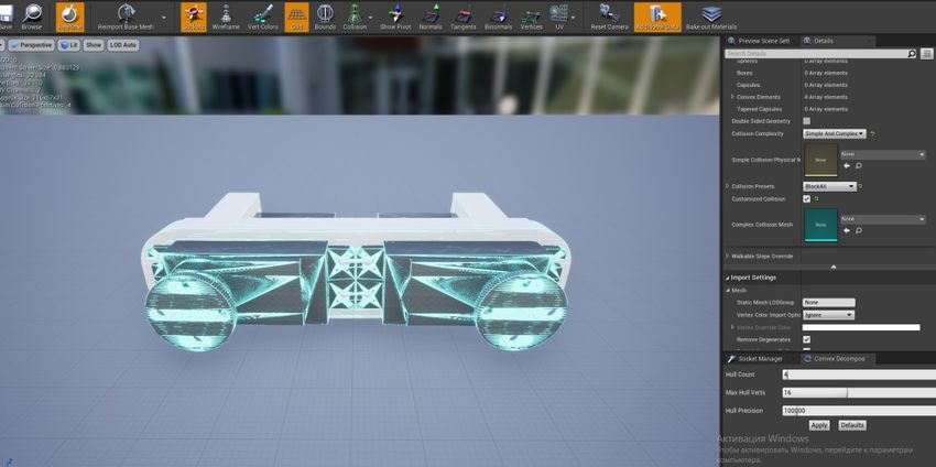
List of Abbreviations

API:      Application programming interface.

BSD:      Berkeley Software Distribution.

GL:       Global lighting.

GPU:      A graphics processing unit.

G-code:   The most widely used computer numerical control programming
          language. It is used mainly in computer-aided manufacturing to
          control automated machine tools, and has many variants.

iOS:      A mobile operating system created and developed by Apple Inc.

OpenCV:   Computer Vision library.

OpenGL:   Open Graphics Library.

ROS:      Robot Operating System.

UART:     A universal asynchronous receiver-transmitter.

UV:       Texture coordinates.
1

1 Introduction

This study concerns Unreal Engine 4 for automation, which is based on my
experience in robotics. Over the course of several years, I have created about
10 different robotic projects. In last projects, the robots already had artificial
intelligence that controlled the movement process, an image recognition
system, and the robots were able to communicate with each other. In the next
step, it was planned to implement a project in which the control of a group of
robots would be implemented, where the robots would have more complex
communication with each other, would have artificial intelligence, and would
perform a single task together. A good example would be a game of soccer in
which robots would be the players. The simplest way to implement this project
would be to use robots of the same type, capable of performing motion
commands ("forward", "backward", "turn", "stop") and a unified robot control
system, which would implement the algorithm of robot movement and
communication. However, the process of creating such a project, using classical
development methods, implied great difficulties. This led to search for
alternative means of robots development. ROS was chosen at the beginning.

ROS (Robot Operating System) provides libraries and tools to help software
developers create robot applications. It provides hardware abstraction, device
drivers, libraries, visualizes, message-passing, package management, and
more. ROS is licensed under an open source, BSD license. (1.)

ROS provides great opportunities to develop a large number of different robots.
ROS contains many off-the-shelf frameworks for robot control, a dynamic 3D
simulator (gazebo), and image recognition tools (OpenCV). However, to use
ROS confidently, a good knowledge of programming and the Linux operating
system is required. In the process of learning ROS, some disadvantages were
found: the difficulty to install and configure the components of ROS, the lack of
a graphical development interface, the poor quality of graphics in the 3D-
rendering components. These shortcomings played a decisive role, and the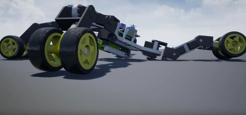
2
search for a platform for the development of robots continued. After a while, the
choice settled on Unreal Engine 4.
Unreal Engine 4 is a state-of-the-art real-time engine and editor that features
photorealistic rendering, dynamic physics and effects, lifelike animation, robust
data translation (2).
The following advantages of Unreal Engine 4 for use in automation can be
highlighted:
A visual scripting system (Blueprints) that does not require strong
programming knowledge and allows you to focus only on the algorithm.
A large number of vector and matrix calculation functions implemented.
Real-time photorealistic rendering.
The presence of a system of physical simulations.
The ability to create a user interface for the created program of any
complexity.
Support for a large number of platforms (Windows, Android, Hololens,
iOS, Linux, Lumin, tvOS).
The main purpose of this work was to develop and implement an inverse
kinematics algorithm in the Unreal Engine 4 environment, and also to create a
physics simulation to test the created algorithm. In the work, the theory of the
main types of inverse kinematics algorithms will be considered. Based on this
theory and also on the basis of knowledge gained during the course
"Palvelurobotiikka" while studying at Metropolia, a unique algorithm of inverse
kinematics will be implemented. This algorithm is designed to control a real
spider-robot. Besides, this algorithm formed the basis for a video game
currently being created, with physically correct movements of robots.
Additionally,to demonstrate the capabilities of the Unreal Engine 4 for its use in
automation and robotics, the following projects developed by me, will be
considered: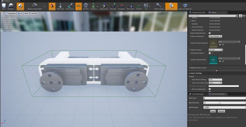
3
1. Implementation of firmware using Unreal Engine 4 for a 3D printer created
for Bloft Design as part of the project of the city of Helsinki to clean up the Baltic
Sea from plastic waste. The project was implemented in Metropolia.
2. Implementation of procedural robot animation for a commercial advertising
project for Digi-Salama project using Unreal engine 4. The project was
implemented in Metropolia.
This work will be useful in the following cases:
In the development of systems for 3D simulation of automation
processes in real time.
When creating unique devices where 3D visualization is required.
To create high quality procedural 3D animation. Game engines are
unique tools for creating high quality procedural 3D animations, the only
competitor of which is “Houdini” - 3D graphics and 3D simulation
package. Game engines are inferior in graphics quality compared to
"Houdini", but significantly gain in rendering speed. For example,
rendering 1 frame in “Houdini” can take up to 1 hour, and Unreal Engine
4 is capable of rendering in real time 25 frames per second.
When creating systems using inverse kinematics. The inverse kinematics
algorithm implemented in this work was tested on a real robot and,
accordingly, can be easily modified for any project that requires inverse
kinematics.
2 Game Engine
2.1 The Operating Principle of a Game Engine.
A game engine, also known as a game architecture, game framework, or game
frame, is a software development environment designed for people to build
video games. Developers use game engines to construct games for consoles,
mobile devices, and personal computers. The core functionality typically
provided by a game engine includes a rendering engine (“renderer”) for 2D or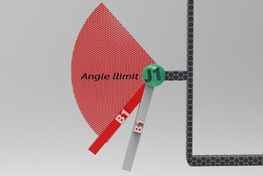
4

3D graphics, a physics engine or collision detection (and collision response),
sound, scripting, animation, artificial intelligence, networking, streaming,
memory management, threading, localization support, scene graph, and may
include video support for cinematics. (3.)

A game engine (Figure 1) consists of three smaller engines and various tools:
rendering engine, math engine, physics engine, animation tools, audio tools,
multiplayer and networking tools, virtual reality tools, world editors, artificial
Intelligence.

Figure 1. Game engine

2.1.1 The Rendering Engine

The rendering engine allows to generate a realistic final view from a 3D model.
Each render engine works on the basis of the GL (global lighting), that is, it
calculates the light produced by the different light sources at a point and its
average on a given surface. (4.)
5 Figure 2. The rendering engine The main part of the rendering engine is the render manager. The rendering manager extracts rendering information from each object. This information is then passed to the GPU through OpenGL buffers. Once in the GPU, the rendering information is processed by OpenGL Shaders. Normally, each game object contains the following rendering information: vertex position, UV coordinates, normals, textures. The GPU uses the vertex position to assemble the geometry of the object. It uses the normal data for lighting operations. And it uses the UV coordinates and texture to apply images to the object. (5.) 2.1.2 The Math Engine The math engine is an API that contains functions that allows 3D objects to translate/rotate. (6.) The math engine handles all linear algebra operations, geometric operations, vectors operations and matrices operations. The math engine (Figure 3) contains these operations: Basic math operations: addition, subtraction, multiplication, division. Geometric operations: rotate, scale, reflect, translate.
6 Vector operations: addition, subtraction, dot product, cross product. Matrix operations: transformation, transpose, inverse, identity. Figure 3. The math engine 2.1.3 The Physics Engine The physics engine provides an approximate simulation of certain physical systems, such as rigid body dynamics (including collision detection), soft body dynamics, and fluid dynamics. Game engines use real-time physics mechanisms based on simplified calculations to compute in time for the game to respond at an appropriate rate for game play. (7.) Figure 4. The physics engine
7
The physics engine determines the position and velocity of an entity. It does this
by integrating the external forces acting on the entity. The most common
external force acting on an entity is gravity. By integrating the force of gravity we
get the velocity and position of the entity. This information is then used to
provide the illusion that the entity is falling. In a nutshell, the physics engine
responsibility is to integrate the equation of motion. (5.)
Physics engines employed in game engines include:
Ragdoll physics - simulate the interaction of a physical body with its
geometric environment. For example, to show a character falling down a
flight of stairs, an engine might calculate the collision and motion of each
limb and stair. Instead of being animated beforehand, each motion of the
character's body would be uniquely computed in real-time.
Particle physics - simulate the motion of many small, similar things
emitted from a common source. Examples of particle physics include
shrapnel from a bomb, sparks from a power line, or lava erupting from a
volcano. In the case of a liquid, such as lava, the physics engine may
also compute fluid dynamics. Cloth modeling - simulates the realistic
motion of cloth, such as a shirt, cape, or flag. (8.)
2.2 Unreal Engine 4
One of the most popular and widely used game engines is the Unreal Engine,
which is owned by Epic Games. It is essentially a game development multi-
platform engine designed for businesses of all sizes that helps use real-time
technology to transform ideas into engaging visual content. The original version
was released back in 1998 and 19 years later it continues being used for some
of the biggest games. The strength of the Unreal Engine is its ability to be
modified enough that games can be made into very unique experiences.
However, this requires skilled developers with vast experience. (9.)8 Main advantages of Unreal Engine 4: open-source engine, the readiness of pre- made assets, blueprints visual scripting language, photo-realistic images, the engine is cross-platform, friendly with external software. (10.) The main difference between Unreal Engine 4 and other game engines is the presence of the Blueprint Visual Scripting System. Figure 5. Example of the blueprint visual scripting in Unreal Engine 4 The Blueprint Visual Scripting (Figure 5) system in Unreal Engine is a complete gameplay scripting system based on the concept of using a node-based interface to create gameplay elements from within Unreal Editor. As with many common scripting languages, it is used to define object-oriented (OO) classes or objects in the engine. This system is extremely flexible and powerful as it provides the ability for designers to use virtually the full range of concepts and tools generally only available to programmers. In addition, Blueprint-specific markup available in Unreal Engine's C++ implementation enables programmers to create baseline systems that can be extended by designers. (11.) Figure 6. Movie the Mandalorian (Unreal Engine 4 render quality) (12)
9

Unreal Engine 4, in addition to the gaming industry, is used to create various
kinds of simulations for making self-driving cars. Also, thanks to its high quality
rendering capabilities, Unreal Engine 4 is used in architectural visualization and
films making ("Star wars", "The Mandalorian" (Figure 6)).

3 Creating Firmware and Real-time Simulation Using Unreal
  Engine 4

3D printer (Figure 7) which was developed by our team. It is the largest 3D
printer in Finland, measuring approximately 3 meters base diameter, 4 meters
high. The extruder of this printer is moved by pulling and loosening 9 metal
cables attached to it. A motor is responsible for the tension of each cable using
a pulley system. Accordingly, the movement of the extruder from one point to
another is carried out by means of 9 powerful (1.5 kilowatts) brushless motors.

Figure 7. 3D printer

3.1    Motors Control

The motors are controlled as follows (Figure 8):
   1. The firmware generates commands to control the motors
   2. The control commands were sent to the arduino MEGA 2560 via USB.
   3. Arduino splits motor control commands for each motor.
   4. Arduino sends motor control commands to motor controllers via UART.
10 Figure 8. 3D printer motor control circuit 3.2 Firmware Features The main task of the firmware is to determine the lengths of the cables per unit of time and, depending on this, form a control command for each motor. Each movement of the extruder uses all 9 motors. When using classic software development tools, it is necessary to implement a large amount of computation. But if Unreal Engine 4 is used, then the need for any complex calculations disappears, since the game engine already has ready-made vector calculation functions. And the whole algorithm will be based only on two scripts implemented in Unreal Engine 4 (Figure 9): a script for calculating the distance between two points and a linear interpolation script required to break the extruder motion vector into separate points. Figure 9. 3D printer blueprints.
11
Capabilities of the created firmware for a 3D printer on Unreal Engine 4:
Reading from a file containing G-code. The firmware implements the
execution of basic control commands for the 3D printer: G0, G1, G92.
Moving the extruder in accordance with the G-code commands.
Management of 3D printer and printing settings (printing speed,
adjustment of cable lengths) in real time.
Management of printing modes (“start”, “stop”, “reverse”).
Visual 3D simulation in real time (Figure 10).
Implements user interface for displaying printer parameters in real time.
Figure 10. Testing the firmware using Unreal Engine 4.
4 Creation of Procedural Animation for Automation Systems
Using Unreal Engine 4
A procedural animation is a type of computer animation, used to automatically
generate animation in real-time to allow for a more diverse series of actions
than could otherwise be created using predefined animations. (13.)
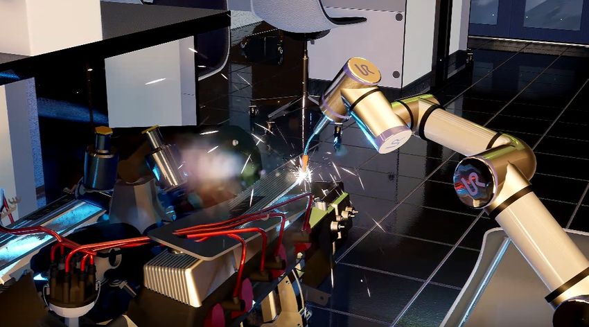
Unreal Engine 4 has extensive tools for creating high-quality (Figure 11)
procedural animations and simulations.12 Figure 11. Frame from a presentation created with Unreal Engine 4. In this section, we will consider several examples of creating procedural animation in the Unreal Engine 4 environment. These animations were created for the “Digi-Salama” project to present automation technologies. 4.1 Lidar Procedural Animation The lidar algorithm implemented in Unreal Engine 4 for creating a simulation completely repeats the work of a real lidar. This became possible thanks to the use of the tracing function (LineTracebyChannel (Figure 12)), which functions as follows - the start and end coordinates are set and if an obstacle is encountered between these points, the function returns the collision parameters. Basic collision parameters: coordinates of the collision point, distance to the object, object name, collision time. Figure 12. Tracing function.
13

The tracing function is similar in effect to the distance sensor in automation.
Accordingly, to realize the work of the lidar, it is necessary to rotate about the
starting point. But since only the coordinates of the start and endpoints can be
supplied to the input of this function, the task is to somehow move the endpoint
around the circle. The easiest way to accomplish this task is to use the vector
computing functionality of Unreal Engine 4. The algorithm is implemented as
follows:
   1. A primitive is added - a cylinder, the coordinates of the center of which
       will determine the starting point. Also, during the simulation, the cylinder
       will rotate around its axis by a certain angle (in the current example, by 3
       degrees) per unit of time (the angular scanning speed depends on this
       value.). To do this, use the function: “AddRelativeRotation” (Figure 13).

       Figure 13. Function “AddRelativeRotation”.

   2. The starting and ending points of the trace are determined. The starting
       point is determined using the “GetWorldTransform” function (Figure 14),
       which gives the following cylinder parameters: “location”, “rotation”,
       “scale”. The value of the “location” parameter determines the coordinates
       of the starting point. To determine the coordinates of the endpoint of the
       tracing, it is necessary to find the direction of the vector looking to the
       right of the cylinder using the “Get Right Vector” function, which uses the
       rotation values. Further, the direction of the vector is multiplied by the
       scanning radius in centimeters (in this case, by 700 centimeters). Then
       the resulting value is added to the coordinate of the starting point of the
       trace and the output is the coordinate of the ending point of the trace.
14
Figure 14. Сalculating the starting and ending points for tracing.
3. A red scan line (simulated laser beam) and a green collision detection
sphere are drawn (Figure 15).
Figure 15. Scan visualization.
As a result, if only the display of red lines and green spheres is implemented,
the scan result is obtained (Figure 16).
Figure 16. Scan result.15
Using this method of creating a simulation, it becomes possible to change the
simulation parameters in real-time: radius and scanning speed.
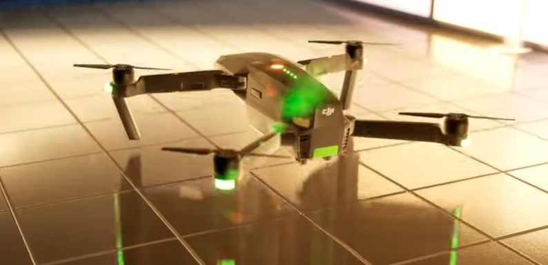
4.2 Drone Procedural Animation
To create procedural animation, it needs a 3D model (Figure 17) of the drone
and four propellers with separate models. When creating a procedural
animation algorithm, the real flight behavior of the drone will be taken as a
basis.
Figure 17. Frame from a presentation created with Unreal Engine 4.
The algorithm will consist of three stages, which will be executed one after the
other:
Vertical rise to a certain height.
Rotation around its own axis at a certain angle with the beginning of a
uniformly accelerated forward movement.
Equally accelerated forward movement up to a certain value, after which
a uniform forward movement.
Figure 18. Function “AddRelativeRotation”.16 Also, during the entire procedural animation, the rotation of the propellers occurs, which is implemented using the “AddRelativeRotation” (Figure 18) function, which rotates the propellers by a certain angle per unit of time. For sequential execution of the stages of the algorithm, the function “Switch on Int” (Figure 19) is used, which redirects the program execution depending on the input value (Index), which will change after the execution of each stage of the algorithm. The initial value of the variable “Index” = 0, after the execution of each part of the algorithm, the value will be increased by one. Figure 19. Function “Switch on Int”. The first stage of the algorithm (Figure 20) implements the rise of the drone to a certain height (180 cm) using the “AddRelativeLocation” function, which changes the position of the drone by a certain value per unit of time (along the z-axis by 0.4). After the drone has climbed to the desired altitude, the program proceeds to the next stage. Figure 20. The part of the algorithm for the drone to climb.
17

At the next stage (Figure 21), the algorithm implements simultaneously the
rotation of the body and uniformly accelerated forward movement. After the
angle of rotation reaches the desired value (20 degrees), the program proceeds
to the execution of the last stage.

Figure 21. Rotate and uniformly accelerated motion forward.

At the last stage (Figure 22), the acceleration reaches a certain value (10 units)
and then the drone moves at a constant speed.

Figure 22. Forward movement.

5 Creation of Inverse Kinematics Algorithms in the Unreal
  Engine 4 Environment

5.1    Inverse Kinematics

The production of realistic and plausible motions has been a long-standing
problem for scholars in many fields, including robotics technology and computer
graphics. During recent decades, several approaches have been implemented
18

for solving the inverse kinematics (IK) problem; IK is a method for computing
the skeletal configuration of a figure via estimating each individual degree of
freedom (DoF) in order to satisfy a given task. IK finds applications in many
areas where the animation and or control of different virtual creatures is
necessary. IK methods are also frequently used in the video games industry
and in the field of computer-aided ergonomics, especially in human model
development and for simulation purposes. However, most of the currently
available IK solvers seem to have drawbacks, such as erratic discontinuities
and singularities. (14.)

5.2    FABRIK

Forward And Backward Reaching Inverse Kinematics (FABRIK) is an IK
algorithm that uses an iterative approach, finding joint positions by locating a
point on a line. FABRIK first checks if the target is reachable, and if it is, the
algorithm iterates until the end-effector reaches the target or a maximum
number of iterations is reached. The first step in one iteration is done forwards;
it adjusts each joint angle one at a time, starting from the last joint in the chain
and working its way to the root. The second step is done backwards in the
same way. It then iterates until the end-effector has reached the target or is
close enough. (15.)

The main advantages of the FABRIK approach are its simplicity, the ease with
which it can be fit into various models, the support of direct optimizations and its
ability to control multiple end effectors, making it ideal for applications in
systems that require real-time computation. (13.)

Figure 23. A forward (top row) and backward (bottom row) reach in FABRIK.
19 The joint transforms in the forward step are computed by moving the end- effector to target and the new positions of the following joints are found on the lines between the next joint position and the current position, as seen in Figure 23. This is likely to make the root move away from its original position, and that is why the backward step is done the same way, but the root’s original position is treated as target and the root is moved to its original position. The algorithm is fast and it takes few iterations to converge (15.) 5.3 Implementing Inverse Kinematics Algorithm in Unreal Engine 4 The inverse kinematics algorithm will be developed to control a spider robot consisting of 12 servos (3 servos per leg). Accordingly, the inverse kinematics algorithm should take into consideration the features of the servo motor: the servo motor can only rotate in one plane, the servo motor has a limited angle of rotation. Implementing the limitations associated with the principle of operation of a servo motor is the most difficult task in developing an inverse kinematics algorithm. The developed inverse kinematics algorithm is based on the principle of operation of the FABRIK algorithm, but for this specific task it was modified to reduce the number of iterations and improve performance. The main difference from the FABRIK algorithm is the presence of a connection between the positions of the first joint and the position of the target of movement, based on which the remaining joints are aligned. Figure 24. Initial position of bones and joints.
20

Consider one robot leg with three joints (J1, J2, J3) and three bones (B1, B2,
B3). Each bone has a fixed length (L1, L2, L3). The task of the algorithm is to
line up the bones between the J1 joint and the target (yellow cylinder in the
Figure 24), whose position will change. Figure 24 defines the initial position of
the bones and joints. Further, it is necessary to introduce constraints related to
the planes of rotation of the joints: the J1 joint can rotate only in the horizontal
plane, and the J2 and J3 joints only in the vertical plane built through the J1, J2,
and J3 joints. After moving the target to an arbitrary point, the work of the
algorithm can be divided into stages:

1. Construction of the reference planes.

The inclusion of these planes in the algorithm allowed to significantly speed up
the process of calculating the positions of bones and joints, taking into account
the constraints introduced. The horizontal plane passing through the J1 joint
and the vertical plane built through the J1 joint and the target will be used as
reference planes (Figure 25). Further on this plane will be located the J2 and J3
joints.

Figure 25. The vertical reference plane.

To define a plane in Unreal Engine 4, it needs to calculate the normal vector of
that plane. To calculate the normal vector of the vertical plane passing through
21

the J1 joint and the target, it is necessary to subtract the value of the
coordinates of the J1 joint and the coordinates of the target along the “x” axis
and along the “y” axis and set the coordinate value along the “z” axis to zero
(Figure 26).

Figure 26. Calculating the normal vector of the vertical plane.

The values of the horizontal plane normal vector are determined only by the
value of the joint J1 coordinate along the “z” axis. The values along the “x” and
“y” axes are set to zero (Figure 27.).

Figure 27. Calculating the normal vector of the horizontal plane.

2. Calculation of the coordinates of the new position of the joints (backward
  reaching).

New joint positions are calculated one by one, starting at J3, then J2 and J1.
Next, the algorithm for calculating the new position of the J3 joint will be
described, which consists of two stages: projecting the joint on the reference
vertical plane and determining the new position of the joint.
22
Figure 28. Projection of joints on the vertical reference plane.
To calculate the coordinates of the J3 joint projected on the vertical reference
plane (the projected joints in Figure 28 are marked with light purple color), it is
necessary (Figure 29):
Multiply the direction vector from the target to the original position of the
J3 joint by the length of the B3 bone
Using the normalized (calculated using the “Clamp” function) plane
normal vector, calculated in the previous step, calculate the projection
vector on the plane using the “Project Vector on to Plane” function.
Add the coordinates of the projection vector to the coordinates of the
target.
Figure 29. Calculation of the projected on the plane coordinates of the
joint J3.23
To calculate the coordinates of the new position of the joint J3, it is necessary
(Figure 30):
Calculate the direction vector going from the “target” to the joint J3
projected on the vertical reference plane.
Multiply the direction vector by the length of the bone B3.
Add the resulting value to the coordinates of the target.
Figure 30. Calculation of the new position of the joint J3.
As a result of the calculations, the coordinates of the new position of the J3 joint
were determined (Figure 31 - the new position of the joint is highlighted in red).
The coordinates of the new position of the J2 joint are calculated in the same
way, but instead of the coordinates of the target, the coordinates of the new
position of the J3 joint are used. The calculation of the new position of the J1
joint is also performed in a similar way, only the horizontal plane must be used
as a reference plane, and instead of the target, the coordinates of the new
position of the J2 joint must be used.
Figure 31. A new position of the joints.24
As a result of the backward reaching, the coordinates of the new positions of
the joints were obtained, taking into account the constraints. The accuracy of
the calculations is determined by how far apart are the positions of the original
J1 joint (the initial position of the joint J1 is shown in green 8 in green in the
Figure 31) and the new position of the J1 joint (the new position of the joint J1 is
shown in red in the Figure 31).
3. Calculation of the coordinates of the new position of the joints (forward
reaching)
The part of the forward reaching algorithm repeats the backward reaching
algorithm with the addition of the following changes:
The new position of the J2 joint is calculated first, using the coordinates
of the initial position of the J1 joint as the target.
After that, the coordinates of the new joint position J3 are calculated
using the coordinates of the new joint position J2 as the target.
The last one calculates the coordinates of the new position of the “target”
using the coordinates of the new position of the vector J3.Accordingly,
when choosing an unattainable target, the algorithm will choose the
closest available position to it.
Figure 32. Angle limit.25
The main difference between the forward reaching algorithm and the backward
reaching algorithm is that the rotation angle constraints are introduced here (the
servo motor has a limited rotation angle). If the angle of rotation (specified by
the user) is exceeded (gray bone B1 in Figure 32), the algorithm will move the
position of the joint to the position corresponding to the maximum angle of
rotation (red bone B1 in Figure 32).
To calculate the angle, it needs to enter an additional bone A, which
corresponds to the initial position of the bone B1 ( ). Knowing the position
of bones A and B1, it becomes possible to calculate the length of C (Figure 33).
For known lengths B1, A, and C, it is possible by the cosine theorem:
(1)
Figure 33. Calculating the angle.
If the angle ( ) exceeds the allowable angle ( ) (Figure 35.) then it is necessary
to move the bone to a position at which the angle will be equal to . Bone
displacement is implemented as follows (Figure 35.):
Let us introduce the notation: corresponds to the position of the bone
without taking into account the angle constraint, the segment BA is an26
imaginary auxiliary bone,the segment lengths AB = AC = , the segment
length BC = , the segment AE corresponds to the new position of the
bone,the vector is the direction vector going from point A to point D,
the vector is a direction vector going from point B to point C.
To calculate the direction vector, use the function “Get Unit Direction
(Vector)” (Figure 34.)
Figure 34. Function “Get Unit Direction (Vector)”
The first step is to calculate the coordinates of point D to calculate the
direction vector :
D= (2)
Next, the coordinates of point E are calculated:
E= (3)
Figure 35. Correction of the angle.27
This operation is performed with all bones, as a result of which the position of
the bones is adjusted taking into account the maximum angle of rotation. Also in
this part of the algorithm, the angle of rotation is calculated, the values of which
will be used for physical simulation and for controlling the servo motors of a real
robot. To improve the accuracy, the forward and backward reaching procedures
are repeated 10 times.
5.4 Physical Simulation for the Inverse Kinematics Algorithm
A 3D model of a real spider robot will be used to create a physics simulation
(Figure 36). The goal of creating a physics simulation is:
Testing the inverse kinematics algorithm created in the previous part.
Determine the behavior of the spider robot before creation.
Creation of a computer game based on the physically correct behavior of
robots.
Figure 36. 3D model for physical simulation.28
There are three steps to creating a physics simulation:
creating a collision for each part of the 3D model,
setting physical parameters for each part of the 3D model,
configuration and management of physical constraints.
Collision creation.
Configuring collisions is necessary to detect intersections of two or more
objects. Thanks to the collision system in Unreal Engine 4, objects interact with
each other, and setting the object collision parameters is a prerequisite for
implementing a physics simulation. To create a physical simulation of the spider
robot, the default collision pattern will be used, which implies blocking all objects
(Figure 37).
Figure 37. Setting the collision parameters.
Another important point for setting up collisions is setting the collision volume,
which will be used to set the collision boundaries.
There are two ways to define the collision volume:
The simple method (Figure 38).
In this method, the boundaries of the interaction object are set using
geometric primitives (cube, sphere, capsule). This method has low
accuracy but high perfomance.29
Figure 38. The simple method to define a collision volume.
The complex method (Figure 39).
In this method, the boundaries of the interaction objects are defined by
the boundaries of the model itself. This method is highly accurate but has
low performance due to the need for a large number of calculations.
Figure 39. The complex method to define a collision volume.
For the current task, there is no need for high accuracy, so for the sake of
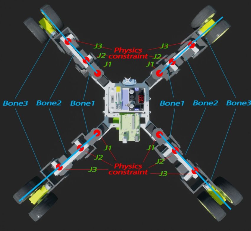
performance, a simple method of setting the amount of collision will be used.30 Setting physical parameters. After setting up the collision, the next step is to turn on the physics simulation and set up the basic physical parameters (Figure 40): the mass value of the object and the linear and angular damping values, which affect the linear and angular displacement resistance. In physics simulation, various unwanted angular and linear oscillations can occur. Damping values can be used to compensate for this effect. The values of these parameters can be adjusted during the simulation to achieve the best result. Figure 40. Physical parameters of the simulation. Physical constraints. The last step for creating a physics simulation is to add physical constraints (Figure 36), the main task of which is to create a hinge connection between two objects, the centers of rotation of which will be determined by the position of the physical constraint. With physical constraints, it can constrain the planes of rotation, constrain the rotation angle, and also set the force (parameter “Strength” in Figure 41), which will act to rotate both objects by the angle specified by the “Target Orientation” parameter (Figure 41). If with the help of a physical constraint to rotate only in one plane, set an angle limitation, and set a force, then the behavior of two objects connected by a physical constraint will be completely analogous to the behavior of a servomotor.
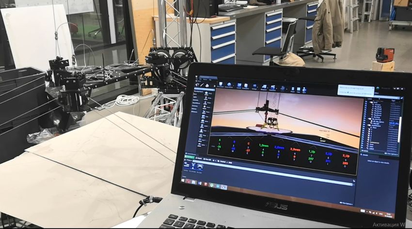
31

Figure 41. Configuring the parameters of the physical constraint.

To create a physical simulation, it is necessary to use the values of the angles
obtained in the part that implements the inverse kinematics algorithm, and feed
these values to the input of the “Set Angular Orientation Target” function, which
sets the angle of rotation of the physical constraint. (Figure 42)

Figure 42. Function “Set Angular Orientation Target”.

After the operations described above for all parts of the robot, as well as setting
up all (12 pieces) of physical constraints, it is possible to realize a physical
simulation (Figure 43) if it is fed in real-time the angle values obtained with the
inverse kinematics algorithm to all physical constraints.
32

Figure 43. Physics simulation of a spider robot.

6 Conclusion

As a result of the work done, an inverse kinematics algorithm and a physical
simulation of a spider robot were implemented in the Unreal Engine 4 game
engine. Additionally, the use of the Unreal Engine 4 game engine for
creating procedural animations was considered, as well as the use of the
game engine to control the automation system using the example of creating
firmware for 3D printers.

The inverse kinematics algorithm developed in this work can be easily modified
to control any robot consisting of any number of servomotors and allows to take
into account the rotation angle constraints for a particular servo motor. Also, this
algorithm, implemented in the Unreal Engine 4 environment, can be used for
training purposes, since the game engine allows you to separate and visualize
each stage of the algorithm.

The physics simulation created in this work allows simulating the behavior of a
real spider robot before creation. This is useful when choosing the
characteristics of the robot being created (leg lengths, mass distribution), and
also allows you to calculate the required power that the servomotors should
have. Additionally, this simulation, together with the inverse kinematics
33

algorithm, is used to create a game with the physically correct movement of
robots.

The process of creating firmware for a 3D printer, which was touched upon in
this work, was created as part of a city project to clean up the Baltic Sea. The
use of a game engine for creating firmware is a unique solution and gives a
huge potential for the development of this project.
34

References

1. Open Robotics. Robot Operating System [online]. June 2020. URL:
   http://wiki.ros.org. Accessed 10 April 2021.
2. Epic Games. Make something Unreal [online]. URL: https://www.unrealen
   gine.com/en-US. Accessed 10 April 2021.
3. Thomas Wilfred. What is the best game development engine? [online].
   June 2020. URL: https://dev.to/thomaswilfred15/what-is-the-best-game-dev
   elopment-engine-2e47. Accessed 11 April 2021.
4. Angel Jimenez de Luis. What is a 3D Rendering? [online]. January 2020.
   URL: https://www.domestika.org/en/blog/2738-what-is-a-3d-rendering.
   Accessed 11 April 2021.
5. Harold Serrano. How does a Game Engine work? An Overview [online].
   January 2016. URL: https://www.haroldserrano.com/blog/how-do-i-build-a-
   game-engine. Accessed 11 April 2021.
6. Harold Serrano. 3D Math Engine Project [online]. URL: https://www.harolds
   errano.com/math-engine-project. Accessed 13 April 2021.
7. Physics    engine   [online].   URL:   https://www.wikiwand.com/en/Physics
   engine. Accessed 13 April 2021.
8. Physics engine [online]. July 2019. URL: https://www.computerhope.com/
   jargon/p/physics-engine.htm. Accessed 13 April 2021.
9. Renana Dar. Top 7 Gaming Engines You Should Consider for 2021 [online].
   February 2021. URL: https://www.incredibuild.com/blog/top-7-gaming-engin
   es-you-should-consider-for-2020. Accessed 14 April 2021.
10. Colleen Jansen. Benefits of using Unreal Engine for your next Game app
   development [online]. October 2019. URL: https://www.whatech.com/gam
   es/press-releases/622394-benefits-of-using-unreal-engine-for-your-next-
   game-app-development. Accessed 14 April 2021.
11. Epic Games. Blueprint Visual Scripting [online]. URL: https://docs.unreale
   ngine.com/en-US/ProgrammingAndScripting/Blueprints/index.html.
   Accessed 14 April 2021.
35

12. Cal Jeffrey. Disney uses Epic's Unreal Engine to render real-time sets in
   The Mandalorian [online]. December 2019. URL: https://www.techspot.com/
   news/82991-disney-uses-epic-unreal-engine-render-real-time.html.
   Accessed 15 April 2021.
13. Procedural animation [online]. 2020. URL: https://www.wikizero.com/en/
   Procedural_animation. Accessed 15 April 2021.
14. Aristidou Andreas, Chrysanthou Yiorgos, Lasenby Joan. Extending
   FABRIK with model constraints [online]. Department of Computer Science,
   University of Cyprus: Nicosia, 1678, Cyprus; February 2015.
   URL: http://andreasaristidou.com/publications/papers/Extending_FABRIK_
   with_Model_C%CE%BFnstraints.pdf. Accessed 16 April 2021.
15. Bornold Jonas, Svantesson Joanna. A Real-Time Adaptation of Inverse
   Kinematics for Motion Capture [online]. Chalmers University of Technology,
   University   of   Gothenburg,   Department   of   Computer    Science   and
   Engineering: Göteborg, Sweden; June 2015. URL: https://publications.lib.
   chalmers.se/records/fulltext/219734/219734.pdf. Accessed 18 April 2021.
Appendix 1
                                   1 (1)
Lidar blueprints

Figure 44. Lidar blueprints
Appendix 2
1 (1)
Drone blueprints
Figure 45. Drone blueprintsAppendix 3
1 (4)
Inverse kinematics algorithm blueprints
Figure 46. Inverse kinematics algorithm blueprints (backward reaching).Appendix 3
2 (4)
Figure 47. Inverse kinematics algorithm blueprints (forward reaching).Appendix 3
3 (4)
Figure 48. Function “Vector Fully Calculate”.
Figure 49. Function “Angle Between 2 Vectors”.Appendix 3
4 (4)
Figure 50. Function “Get Vector on Plane”.You can also read