UPGRADING TORONTO'S UNIVERSITY SUBWAY LINE VENTILATION SYSTEM
←
→
Page content transcription
If your browser does not render page correctly, please read the page content below
- 157 -

         UPGRADING TORONTO’S UNIVERSITY SUBWAY LINE
                    VENTILATION SYSTEM
                            N. Rhodes, M.McCulloch & H.-W. Wong
                                    Hatch Mott MacDonald
                                      475 Park Ave South
                                  New York, NY 10016, USA

INTRODUCTION
This paper presents the results of work undertaken as part of the Toronto Transit
Commission’s University Subway Line Fire Ventilation Upgrade Program. The design intent
is to upgrade, to the greatest extent practical, the tunnel ventilation system to meet the current
National Fire Protection Association (NFPA) 130 Standard for Fixed Guideway Transit and
Passenger Rail Systems [1]. The existing tunnel ventilation system is not fire-rated and does
not have the necessary capacity for maintaining a smoke-free egress route in the event of any
fire larger than a nuisance fire.

The work has involved investigating the potential for both upgrading the existing fans and for
installing new fans in existing blast relief shafts. During normal operating conditions the
requirement for blast relief in order to alleviate the piston effect of trains is necessary. Hence
the installation of fans in blast relief shafts would require that the fans are allowed to ‘free
wheel’ when not in operation, allowing blast relief through the fans themselves.

The University Subway Line was simulated using the Subway Environment Simulation (SES)
software [2]. SES was used to determine the required fan size for meeting the critical velocity
requirement in the case of a fire in the running tunnels. Having established the fan size to
meet the design criteria in the running tunnels, the SES software was then used to simulate
station fires, so that boundary conditions could be set for CFD simulations of fires at stations.
Hence, the work has also involved the development of three dimensional CFD models which
predict air velocities, smoke distribution, temperature and related flow properties for the
prescribed cases and boundary conditions. This enables an assessment of the performance of
the fire ventilation upgrades during a fire incident inside the station and whether there is a
tenable environment for safe egress within the time allowed for by NFPA 130 egress criteria.
The standard requires a 4-minute duration for platform evacuation, a 6-minute duration for
passengers to reach a point of safety and defined criteria for temperature exposure, visibility,
and velocity along the egress paths.

Of the five stations modelled, results are presented for Museum Station; a natural ventilation
simulation base case was performed to study the existing conditions, i.e. in the absence of
mechanical ventilation. The results from the natural ventilation case are compared with two
ventilation schemes, an all exhaust ventilation scheme and a push pull ventilation scheme.

TUNNEL & STATION CONFIGURATION
The University Subway Line entered revenue service on 28th February 1963, extending the
Yonge Line from Union Station to St George Station and later linking to the Bloor Line at
Bay Station and St George Station, and to the Spadina Line at St George Station. The
connection to Bay Station is no longer used for revenue service.

                  4thInternational Conference ‘Tunnel Safety and Ventilation’ 2008, Graz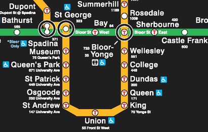
- 158 -

These stations form part of the University Line. Figure 1 shows the section of the TTC
subway system.

                           Figure 1: Section of TTC subway system

The University Line consists of five stations, each with 500-foot (152.4 m) platforms. From
north to south they are:

•      Museum
•      Queen’s Park
•      St Patrick
•      Osgoode
•      St Andrew

Each station has a shaft or shafts at each end. Figure 2 shows the general location of these.
There are fan shafts at:

St George West
Museum South
Queen’s Park North
St Patrick North
Osgoode North
St Andrew South
West of Union (between Union and St Andrew)

                 4thInternational Conference ‘Tunnel Safety and Ventilation’ 2008, Graz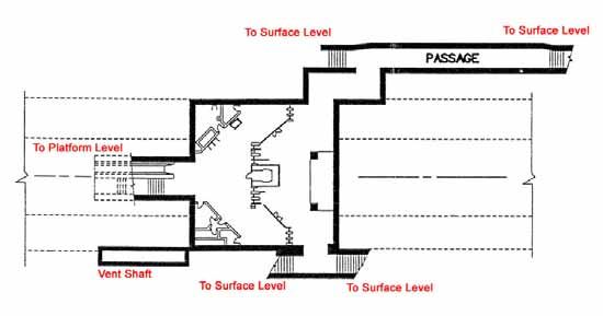
- 159 -

                Existing Structures
                       ST GEORGE                                              BAY

                                    V                             V

                                    V                             V
                                          A               A

                                                      V

                       MUSEUM

                                                      F

                                                  A

                                              F

                       QUEEN’S
                        PARK                                                          Existing Structures

                                              V                                   V      Ventilation Shaft
                                              A
                                              F                                   A      Access Shaft

                                                                                  F      Fan Shaft
                     ST PATRICK
                                                                                         Bored Tunnel
                                              V
                                              A                                          Box Structure
                                              F
                                                                                         Station In Contract

                      OSGOODE
                                                                                         Station Outside Contract

                                              V

                                              V       V

                     ST ANDREW

                                                                                      UNION
                                                      F
                                                              A           F
                                              A
                                                                      F       V

                                        Figure 2: Existing Structures

There are blast relief shafts at:

St George East
Museum North
Queen’s Park South
St Patrick South
Osgoode South
St Andrew North

                  4thInternational Conference ‘Tunnel Safety and Ventilation’ 2008, Graz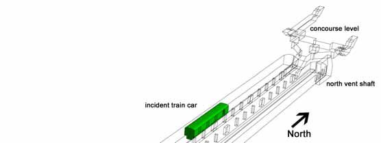
- 160 -

There are also six inter-station access shafts. These are between:
St George and Museum
Museum and Queen’s Park
Queen’s Park and St Patrick
St Patrick and Osgoode
St Andrew and Union (Two in this section)
There is another access shaft between Bay and Museum. This section is not in revenue
service.
The above stations are linked by 1180 m of box structure and 1294 m of bored tunnel. The
bored tunnel section is lined with ribbed cast iron liner and runs between Osgoode Station and
Museum Station. The rest of the line is box structure. Including the stations, the total length of
the University Line between the west end of Union Station and the east end of St George
Station is 3236 m. This excludes the section that is out of revenue service between Museum
Station and Bay Station
The existing box structure has separating walls between the tracks, except at crossovers. The
walls have regular openings of 3.25 m² (35 ft²; 5 ft wide by 7 ft high) at 6.1 m to 7.6 m
intervals. There are three cross-overs to centre tracks. The Union centre storage track has
crossovers immediately to the west (northbound side) of Union station and immediately to the
south of St Andrew station. The centre track south of Osgoode has a crossover immediately to
the south of Osgoode station (Osgoode three track crossover). Most of the section between
Osgoode and Union is triple-track. The triple-track box section has varying width, being
usually about 14.5 m wide in total. The vertical clearance is 3.96 m (13 ft).
There is also a double cross-over between Museum and St George, immediately to the east of
St George.
There are three-track box tunnel segments between Osgoode and St Andrew and between St
Andrew and Union. The centre tracks are separated from the running tunnels by walls with
openings. The openings have an area of 3.25 m² and an interval of about 7 m. The annular
area around a stationary train is less than the open area of two of the wall openings.
The centre track between Osgoode and St Andrew is only open for trains at the Osgoode end
via a three track crossover (Osgoode three track cross over). The centre storage track between
St Andrew and Union (Union storage track) is open to trains at both ends via three track
crossovers.
The presence of the openings prevents effective longitudinal smoke control. If critical velocity
is to be achieved over a burning train the openings would have to be closed, thus creating
separate box segments.

The following alternatives were studied:
   A. Leave the openings as they are. Do not attempt to create critical velocity over the
      incident train. Attempt to keep a tenable environment in the adjacent center track and
      running tunnel. For the section between Osgoode and St Andrew this could include
      enlarging the openings at the St Andrew end of the centre track.
   B. Close all, or almost all, the openings between the centre track and both running
      tunnels. This could be done with sliding doors or by walling up the openings. Jet fans
      would be required if critical velocity was to be achieved.
   C. Install fixed fire suppression in the running tunnels and crossovers. This would not
      require jet fans.

                  4thInternational Conference ‘Tunnel Safety and Ventilation’ 2008, Graz
- 161 -
Alternative A was simulated using a local model with greater detail than the line-wide model
used for the rest of the simulations. These simulations showed that critical velocity could not
be achieved anywhere along the length of a burning train: the whole length of the train could
become engulfed in smoke as smoke would spread both ways from the fire. The only tenable
environment in the incident track would be at least 30 m upstream of the train. The adjacent
tracks would be subject to some smoke contamination, but the opposite running tunnel could
remain tenable. Passengers would have to know that it was the route to safety, and be able to
get there.
The installation of jet fans with Alternative A would not achieve guaranteed longitudinal
smoke control because they could not prevent mixing between the tracks and could not
guarantee that critical velocity is met at the fire site.
DESIGN CRITERIA
The fundamental design criterion for the fire ventilation system in the running tunnels is
compliance with the relevant parts of the current version of NFPA 130. In terms of the tunnel
ventilation system, emergency operations in running tunnels have been modelled based upon
a fire scenario on board a transit vehicle. The analyses focused on determining the ventilation
required to maintain a single evacuation path from the train clear of smoke and hot gases.
Maintaining such a path during a fire emergency enhances passenger safety.
The TVF equipment will be used to produce an air flow rate in the incident ventilation section
such that the velocity is sufficient to prevent back layering of smoke. This is often referred to
as the critical velocity. NFPA 130 defines the critical velocity as “the minimum steady-state
velocity of the ventilation airflow moving toward the fire within a tunnel or passageway that
is required to prevent backlayering at the fire site.” Back layering is defined as “The reversal
of movement of smoke and hot gases counter to the direction of the ventilation airflow.”
The critical velocity calculated for each tunnel cross-section and gradient was increased by
10%, and then multiplied by the tunnel train annular cross-sectional area to produce the
minimum air volume flow criterion. This air volume flow was used as the basic acceptability
criterion for fire ventilation.
In addition to the requirements of NFPA 130, the prevention of smoke spread to adjacent
ventilation sections was also a design goal. For example in the event of a train fire in a tunnel,
smoke being drawn towards a station should not flow past the extract shaft at the end of the
station into the station itself.
For trains on fire at stations and in tunnels, the design must comply with emergency
ventilation requirements in enclosed stations and tunnels as per Chapter 7 of NFPA 130. In
accordance with Section 7.2, the emergency ventilation in is required to provide a tenable
environment along the path of egress from a fire incident and be capable of reaching full
operational mode within 180 seconds.
In accordance with Paragraph 5.5.3.2 of NFPA 130, stations are required to be designed to
permit the evacuation from the most remote point on the platform to a point of safety in 6
minutes or less. Therefore, in order to allow safe evacuation of the station modelling has been
carried out with the ventilation system operated in “push-pull” mode, whereby smoke
ventilation fans are operated in supply and exhaust modes at opposite ends of the stations, and
in “pull-pull” mode, whereby all fans are operated in exhaust mode. This is done in order to
draw fresh air through the station concourse and passenger exits. CFD analysis was carried
out to show the most effective of the alternative ventilation strategies.
4thInternational Conference ‘Tunnel Safety and Ventilation’ 2008, Graz- 162 -
FAN SIZING METHODOLOGY
The initial series of fire simulations was carried out without regard for the space requirements
of the fans; therefore the fan capacity was unlimited. The sole criterion was to achieve NFPA
130 compliance in terms of smoke ventilation. The ideal fan capacity indicated by the
successful simulations was then used to select potential fan units. This enabled an assessment
of the practicality of the installation of fan plant of sufficient capacity in the available existing
space, or in possible future available space. If fans rated at the ideal capacity for NFPA 130
compliance had proved too large for the available space, further simulations would need to be
carried out to assess the benefit of the largest fans that could be accommodated.
SES MODEL
To develop the optimum solution, bearing in mind that NFPA 130 compliance might not be
possible in all locations, the following sequence was planned:
1) Test runs with base model
2) Fire runs for NFPA 130 compliance, with no limit on fan size.
3) Fire runs with ‘realistic’ fan selections and system modifications, including runs
to establish CFD boundary conditions.
4) Environmental runs to assess effect of system modifications, with and without
congestion.
5) Cold flow runs for commissioning purposes, once the system design is finalised.
INTERFACE WITH STATION CFD MODELS
In addition to the simulations carried out for fires in the running tunnels, simulations of train
fires in stations were also carried out. The SES software is a one dimensional simulation
method and due to inherent limitations it is not recommended for the detailed study of station
fires. This is primarily because it is not possible to model the flow of smoke as a stratified
layer. The SES software can only model smoke movement as a homogenous mixture across
the entire cross section. A three-dimensional computational model is more appropriate for
simulating the flow of smoke along and across a station platform, up stairs and through a
concourse. It would be impractical to include enough of the subway system in a CFD model
so that the model itself would be able to be used to simulate the flows in or out of a station
during fan operation. An SES model is more suitable for the simulation of the bulk air flows
in a system, so an SES simulation can be carried out to determine the boundary condition for
the CFD model.
Mass flow rates, in or out of the station headwalls, were used for the boundary conditions at
University Line, i.e. at the interface between the running tunnel and the station. Where there
was an active fan within the bounds of the CFD model, for example at Museum Station, this
was also modelled as a mass flow boundary.
As a check between the SES model and the CFD model, both the SES and CFD models were
run for cold flow conditions, and the air flows and calculated pressure drops from each set of
results were compared. The SES model was then adjusted and predictions checked so that
they were in agreement with the CFD model predictions. The SES station fire simulations
were then re-run to provide the final boundary conditions for the CFD simulations.
The SES model was adjusted to match the CFD model because it is considered that the CFD
model of the stairways, concourse and entrances, predicts losses more accurately than the
conventional method of summing individual component losses from standard references.
4thInternational Conference ‘Tunnel Safety and Ventilation’ 2008, Graz- 163 -
Simulations were carried out for all-exhaust (“pull-pull”) and for longitudinal (“push-pull”)
ventilation modes, with the longitudinal mode being tested in both possible directions. CFD
simulations were then carried out for the two modes. The boundary conditions established for
MuseumStation are given in Tables1and 2.
Table 1: Museum Station Mass Flow Rates – Push-Pull
Museum Station Interface Mass Flow Rate
(kg/s)
North Vent Shaft -120.0
NW Tunnel 50.4
NE Tunnel 59.3
SE Tunnel -23.8
SW Tunnel -24.0
Table 2: Museum Station Mass flow Rates – Pull-Pull
Museum Station Interface Mass Flow Rate
(kg/s)
North Vent Shaft 120.0
NW Tunnel -51.5
NE Tunnel 5.1
SE Tunnel -41.3
SW Tunnel -40.8
PLATFORM LEVEL
Museum Station is split into two levels, a platform and concourse level. A northbound track
and a southbound track run on either side of the centre platform. The length of the platform
from north headwall to south headwall is 152.4 m (500 ft). The platform has a 0.3 percent
slope, where the north end is higher than the south end of the platform. Figure 3 shows a
schematic plan view of the platform level where the columns are clearly marked.
South Headwall North Headwall
South North
Figure 3: Plan view of platform level
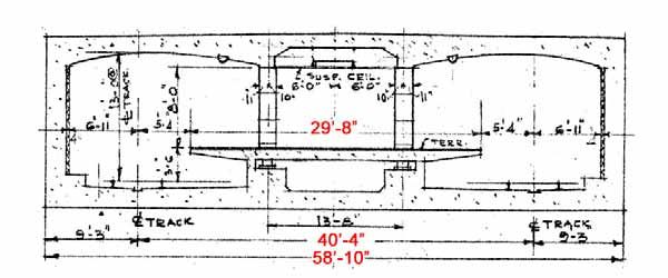
Figure 4 shows a typical cross section through the platform level of the station. The platform
width is 6.30 m (29 ft 8 in). The distance between the two centre lines of track is 12.30 m (40
ft 4 in).
4thInternational Conference ‘Tunnel Safety and Ventilation’ 2008, Graz- 164 -
Figure 4: Cross section of station platform
Figure 5 shows a plan view of the concourse level. There are three connections, one to the
platform level and two connections to grade. The two concourse level connections lead to
grade via an east and west passageway. The passageways contain two sets of staircases, where
the staircase doors are open during revenue service. There is a collector’s booth in the centre
of the concourse level. Figure 6 shows the incident train location for the runs presented in this
paper
West Passageway
East Passageway
NORTH
Figure 5: Plan view of concourse level
4thInternational Conference ‘Tunnel Safety and Ventilation’ 2008, Graz- 165 -
Figure 6: Incident Train Location
Figures 7 to 9 show typical visibility plots determined from the CFD simulations for the
different ventilation modes.
time = 4 minutes (240 seconds)
time = 6 minutes (360 seconds)
Figure 7: Visibility plots, centre of station, natural ventilation
4thInternational Conference ‘Tunnel Safety and Ventilation’ 2008, Graz- 166 -
time = 4 minutes (240 seconds)
time = 6 minutes (360 seconds)
Figure 8: Visibility plots, centre of station, all-exhaust ventilation
Visibility plots, centre of station, all-exhaust ventilation
time = 4 minutes (240 seconds)
time = 6 minutes (360 seconds)
Figure 9: Visibility plots, centre of station, push pull ventilation
The analyses of the simulations determined that existing conditions and egress routes are
improved when subway ventilation fans are operated. The most effective operating mode for
controlling a centrally located fire incident at Museum Station would be to employ an all
exhaust ventilation scheme.
CONCLUSIONS
A model has been developed to investigate effects of the subway ventilation schemes on a fire
scenario at Museum Station. The fire scenario involved a fire incident located at the centre of
a train on the southbound track. Simulations were performed to study the use of all exhaust
and push pull ventilation schemes. A natural ventilation simulation with no mechanical
ventilation was used to compare against the two ventilation schemes to understand the level of
improvements which would be expected from the use of mechanical ventilation.
4thInternational Conference ‘Tunnel Safety and Ventilation’ 2008, Graz- 167 -
The critical locations of this model are platform level staircase interfaces, if the proposed
ventilation scheme is capable of providing a smoke free environment then under NFPA 130
criteria, the staircase would be deemed a location of safety. Comparing Figures 8 and 9
clearly demonstrates that the all exhaust ventilation scheme induces greater mass flow
through both staircases, keeping them clear of smoke, than the push pull ventilation scheme.
This air movement helps prevent air/smoke from moving into the exit stairwells. The push
pull ventilation scheme produced results which demonstrated that the second exit would
become untenable after 5 minutes.
The results of the simulations show that an all exhaust ventilation scheme would be the best
solution at Museum Station.
References
1) TTC Fire Ventilation Upgrade Project Technical Criteria Report, Third Draft, 18
August 2005
2) Subway Environment Simulation Computer Program, Version 4, User Manual,
December 1997
4thInternational Conference ‘Tunnel Safety and Ventilation’ 2008, GrazYou can also read