User Manual RELIANCE Inset Lights 12-inch (RC-RZ-RX-RE-RT-RW-RN-RTN-AC-AS-SW-RS-TC-SB) - ADB Safegate
←
→
Page content transcription
If your browser does not render page correctly, please read the page content below

RELIANCE Inset Lights
12-inch (RC-RZ-RX-RE-RT-RW-RN-RTN-AC-AS-SW-RS-TC-SB)

User Manual
UM-0210, Rev. 3.4, 2021/09/01

A.0 Disclaimer / Standard Warranty
CE certification
The equipment listed as CE certified means that the product complies with the essential requirements concerning safety and
hygiene. The European directives that have been taken into consideration in the design are available on written request to
ADB SAFEGATE.

ETL certification
The equipment listed as ETL certified means that the product complies with the essential requirements concerning safety and
FAA Airfield regulations. The FAA directives that have been taken into consideration in the design are available on written
request to ADB SAFEGATE.

All Products Guarantee
ADB SAFEGATE will correct by repair or replacement per the applicable guarantee above, at its option, equipment or parts
which fail because of mechanical, electrical or physical defects, provided that the goods have been properly handled and
stored prior to installation, properly installed and properly operated after installation, and provided further that Buyer gives
ADB SAFEGATE written notice of such defects after delivery of the goods to Buyer. Refer to the Safety section for more
information on Material Handling Precautions and Storage precautions that must be followed.
ADB SAFEGATE reserves the right to examine goods upon which a claim is made. Said goods must be presented in the same
condition as when the defect therein was discovered. ADB SAFEGATE furthers reserves the right to require the return of such
goods to establish any claim.
ADB SAFEGATE's obligation under this guarantee is limited to making repair or replacement within a reasonable time after
receipt of such written notice and does not include any other costs such as the cost of removal of defective part, installation
of repaired product, labor or consequential damages of any kind, the exclusive remedy being to require such new parts to be
furnished.
ADB SAFEGATE's liability under no circumstances will exceed the contract price of goods claimed to be defective. Any returns
under this guarantee are to be on a transportation charges prepaid basis. For products not manufactured by, but sold by ADB
SAFEGATE, warranty is limited to that extended by the original manufacturer. This is ADB SAFEGATE's sole guarantee and
warranty with respect to the goods; there are no express warranties or warranties of fitness for any particular purpose or any
implied warranties of fitness for any particular purpose or any implied warranties other than those made expressly herein. All
such warranties being expressly disclaimed.

Standard Products Guarantee
Products manufactured by ADB SAFEGATE are guaranteed against mechanical, electrical, and physical defects (excluding
lamps) which may occur during proper and normal use for a period of two years from the date of ex-works delivery, and are
guaranteed to be merchantable and fit for the ordinary purposes for which such products are made.

        Note
        See your sales order contract for a complete warranty description.
        Replaced or repaired equipment under warranty falls into the warranty of the original delivery. No new warranty
        period is started for these replaced or repaired products.

FAA Certified products manufactured by ADB SAFEGATE
ADB SAFEGATE L858 Airfield Guidance Signs are warranted against mechanical and physical defects in design or manufacture
for a period of 2 years from date of installation, per FAA AC 150/5345-44 (applicable edition).
ADB SAFEGATE LED products (with the exception of obstruction lighting) are warranted against electrical defects in design or
manufacture of the LED or LED specific circuitry for a period of 4 years from date of installation, per FAA EB67 (applicable
edition). These FAA certified constant current (series) powered LED products must be installed, interfaced and powered with
and through products certified under the FAA Airfield Lighting Equipment Program (ALECP) to be included in this 4 (four) year
warranty. This includes, but is not limited to, interface with products such as Base Cans, Isolation Transformers, Connectors,
Wiring, and Constant Current Regulators.

UM-0210, Rev. 3.4, 2021/09/01                                                                                                      iii
Copyright © ADB Safegate, All Rights Reserved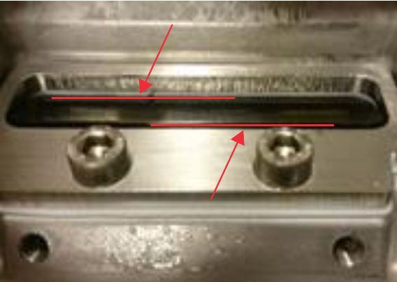
RELIANCE Inset Lights

        Note
        See your sales order contract for a complete warranty description.
        Replaced or repaired equipment under warranty falls into the warranty of the original delivery. No new warranty
        period is started for these replaced or repaired products.

Liability

                    WARNING
                    Use of the equipment in ways other than described in the catalog leaflet and the manual may result in personal injury,
                    death, or property and equipment damage. Use this equipment only as described in the manual.

ADB SAFEGATE cannot be held responsible for injuries or damages resulting from non-standard, unintended uses of its
equipment. The equipment is designed and intended only for the purpose described in the manual. Uses not described in the
manual are considered unintended uses and may result in serious personal injury, death or property damage.
Unintended uses, includes the following actions:

• Making changes to equipment that have not been recommended or described in this manual or using parts that are not
    genuine ADB SAFEGATE replacement parts or accessories.
• Failing to make sure that auxiliary equipment complies with approval agency requirements, local codes, and all applicable
    safety standards if not in contradiction with the general rules.
• Using materials or auxiliary equipment that are inappropriate or incompatible with your ADB SAFEGATE equipment.
• Allowing unskilled personnel to perform any task on or with the equipment.
©   ADB SAFEGATE BV
This manual or parts thereof may not be reproduced, stored in a retrieval system, or transmitted, in any form or by any means,
electronic, mechanical, photocopying, recording, nor otherwise, without ADB SAFEGATE BV's prior written consent.
This manual could contain technical inaccuracies or typographical errors. ADB SAFEGATE BV reserves the right to revise this
manual from time to time in the contents thereof without obligation of ADB SAFEGATE BV to notify any person of such
revision or change. Details and values given in this manual are average values and have been compiled with care. They are not
binding, however, and ADB SAFEGATE BV disclaims any liability for damages or detriments suffered as a result of reliance on
the information given herein or the use of products, processes or equipment to which this manual refers. No warranty is made
that the use of the information or of the products, processes or equipment to which this manual refers will not infringe any
third party's patents or rights. The information given does not release the buyer from making their own experiments and
tests.

iv
Copyright © ADB Safegate, All Rights Reserved
TABLE OF CONTENTS

1.0 Safety ....................................................................................................................................................................................... 1
     1.1 Safety Messages ........................................................................................................................................................................................................ 1
          1.1.1 Introduction to Safety ................................................................................................................................................................................. 2
          1.1.2 Intended Use .................................................................................................................................................................................................. 2
          1.1.3 Material Handling Precautions: Storage .............................................................................................................................................. 3
          1.1.4 Operation Safety ........................................................................................................................................................................................... 3
          1.1.5 Maintenance Safety ..................................................................................................................................................................................... 3
          1.1.6 Material Handling Precautions: Fasteners .......................................................................................................................................... 4
          1.1.7 Material Handling Precautions, ESD ..................................................................................................................................................... 4
2.0 About this Manual ................................................................................................................................................................. 5
    2.1 How to work with the Manual ............................................................................................................................................................................. 6
    2.2 Abbreviations and Terms ........................................................................................................................................................................................ 6
3.0 Introduction ............................................................................................................................................................................ 7
     3.1 Product Information ................................................................................................................................................................................................. 7
     3.2 Dimensions and Weight ......................................................................................................................................................................................... 8
4.0 Installation ............................................................................................................................................................................ 11
     4.1 Unpacking the Unit ................................................................................................................................................................................................ 11
     4.2 Tools Required ......................................................................................................................................................................................................... 12
     4.3 Installation and Removal of the 12-inch Light Fixture ............................................................................................................................. 12
     4.4 Toe-in .......................................................................................................................................................................................................................... 13
     4.5 Light Emission Directions .................................................................................................................................................................................... 15
          4.5.1 Definition of Light Emission Directions ............................................................................................................................................. 15
          4.5.2 RELIANCE IQ0 and RELIANCE IQ1 Schematic Installation Example ....................................................................................... 15
          4.5.3 12‑inch Light Beam Types ....................................................................................................................................................................... 15
5.0 Operation .............................................................................................................................................................................. 17
6.0 Maintenance ......................................................................................................................................................................... 19
    6.1 Basic Maintenance Program ............................................................................................................................................................................... 19
    6.2 Workshop Maintenance ....................................................................................................................................................................................... 19
         6.2.1 Open and close a 12‑inch Fixture ........................................................................................................................................................ 20
         6.2.2 Check the Light Fixture for Water-tightness .................................................................................................................................... 22
         6.2.3 Replace a Light Engine in a 12‑inch Fixture ..................................................................................................................................... 23
         6.2.4 Replace a Prism and its Gasket in a 12‑inch Fixture ..................................................................................................................... 24
         6.2.5 Replace the Bottom Cover and Converter ....................................................................................................................................... 26
         6.2.6 Reset the Fail-Open Converter 2.3 ...................................................................................................................................................... 27
         6.2.7 Reset the Fail-Open Converter 48010921 and 48011111 .......................................................................................................... 28
7.0 Ordering Codes and Spare Parts ........................................................................................................................................ 29
    7.1 Ordering Code (RC-RZ-RX) ................................................................................................................................................................................. 30
    7.2 Spare Parts (RC-RZ-RX) ........................................................................................................................................................................................ 32
    7.3 Ordering Code (RE) ................................................................................................................................................................................................ 34
    7.4 Spare Parts (RE) ....................................................................................................................................................................................................... 36
    7.5 Ordering Code (RT-RW) ....................................................................................................................................................................................... 38
    7.6 Spare Parts (RT) ....................................................................................................................................................................................................... 40
    7.7 Spare Parts (RW) ..................................................................................................................................................................................................... 42
    7.8 Ordering Code (RN-RTN) .................................................................................................................................................................................... 43
    7.9 Spare Parts (RN-RTN) ............................................................................................................................................................................................ 44
    7.10 Ordering Code (AC-AS) ..................................................................................................................................................................................... 46
    7.11 Spare Parts (AC) .................................................................................................................................................................................................... 47
    7.12 Spare Parts (AS) .................................................................................................................................................................................................... 48
    7.13 Ordering Code (SW) ............................................................................................................................................................................................ 49
    7.14 Spare Parts (SW) ................................................................................................................................................................................................... 51
    7.15 Ordering Code (RS) ............................................................................................................................................................................................. 52
    7.16 Spare Parts (RS) ..................................................................................................................................................................................................... 53

UM-0210, Rev. 3.4, 2021/09/01                                                                                                                                                                                                              v
Copyright © ADB Safegate, All Rights Reserved
RELIANCE Inset Lights
TABLE OF CONTENTS

        7.17 Ordering Code (TC) ............................................................................................................................................................................................. 54
        7.18 Spare Parts (TC) ..................................................................................................................................................................................................... 56
        7.19 Ordering Code (SB) ............................................................................................................................................................................................. 58
        7.20 Spare Parts (ICAO SB) ......................................................................................................................................................................................... 60
        7.21 Spare Parts (FAA SB) ............................................................................................................................................................................................ 61
A.0 INTEROPERABILITY ............................................................................................................................................................. 63
B.0 POWER TABLE ...................................................................................................................................................................... 65
C.0 CABLE LOSS .......................................................................................................................................................................... 73
D.0 SUPPORT .............................................................................................................................................................................. 75
    D.1 ADB SAFEGATE Website ...................................................................................................................................................................................... 75
    D.2 Recycling .................................................................................................................................................................................................................... 75
         D.2.1 Local Authority Recycling ....................................................................................................................................................................... 75
         D.2.2 ADB SAFEGATE Recycling ....................................................................................................................................................................... 76

vi
Copyright © ADB Safegate, All Rights Reserved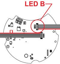
List of Figures

Figure 1: 12‑in shallow base, class 1, direct-mounted fixtures .............................................................................................................................. 11
Figure 2: FAA deep can, class 2, base-mounted fixtures .......................................................................................................................................... 11
Figure 3: Toe-in ........................................................................................................................................................................................................................ 14
Figure 4: Light emission directions .................................................................................................................................................................................. 15
Figure 5: Schematic installation example ...................................................................................................................................................................... 15
Figure 6: Fixture upside down ............................................................................................................................................................................................ 21
Figure 7: Lift up housing ...................................................................................................................................................................................................... 21
Figure 8: Remove gasket ...................................................................................................................................................................................................... 21
Figure 9: Converter with 1 connector .............................................................................................................................................................................. 21
Figure 10: Converter with 2 connectors ......................................................................................................................................................................... 21
Figure 11: Fixture facing down ........................................................................................................................................................................................... 22
Figure 12: Tighten screws .................................................................................................................................................................................................... 22
Figure 13: Replacing a light engine ................................................................................................................................................................................. 23
Figure 14: Tighten screws .................................................................................................................................................................................................... 23
Figure 15: LED board ............................................................................................................................................................................................................. 23
Figure 16: Converter connections ..................................................................................................................................................................................... 24
Figure 17: Remove LED board holder ............................................................................................................................................................................. 25
Figure 18: Remove prism and gasket .............................................................................................................................................................................. 25
Figure 19: New prism into prism gasket ........................................................................................................................................................................ 25
Figure 20: Prism holder edge ............................................................................................................................................................................................. 25
Figure 21: Tighten screws in sequence ........................................................................................................................................................................... 26
Figure 22: Converter with 1 connector ........................................................................................................................................................................... 27
Figure 23: Converter with 2 connectors ......................................................................................................................................................................... 27
Figure 24: 2-way electrical shunt/jumper ...................................................................................................................................................................... 27
Figure 25: Converter with 1 connector ........................................................................................................................................................................... 27
Figure 26: Converter with 2 connectors ......................................................................................................................................................................... 27
Figure 27: Converter with 1 connector ........................................................................................................................................................................... 28
Figure 28: Converter with 2 connectors ......................................................................................................................................................................... 28

UM-0210, Rev. 3.4, 2021/09/01                                                                                                                                                                                                           vii
Copyright © ADB Safegate, All Rights Reserved
RELIANCE Inset Lights
List of Figures

viii
Copyright © ADB Safegate, All Rights Reserved
List of Tables

Table 1: Bidirectional light beam ....................................................................................................................................................................................... 16
Table 2: Unidirectional light beam .................................................................................................................................................................................... 16
Table 3: Interoperability matrix .......................................................................................................................................................................................... 63

UM-0210, Rev. 3.4, 2021/09/01                                                                                                                                                                                              ix
Copyright © ADB Safegate, All Rights Reserved
RELIANCE Inset Lights
List of Tables

x
Copyright © ADB Safegate, All Rights Reserved
1.0 Safety
Introduction to Safety
This section contains general safety instructions for installing and using ADB SAFEGATE equipment. Some safety instructions
may not apply to the equipment in this manual. Task- and equipment-specific warnings are included in other sections of this
manual where appropriate.

1.1 Safety Messages

HAZARD Icons used in the manual
For all HAZARD symbols in use, see the Safety section. All symbols must comply with ISO and ANSI standards.
Carefully read and observe all safety instructions in this manual, which alert you to safety hazards and conditions that may
result in personal injury, death or property and equipment damage and are accompanied by the symbol shown below.

                    WARNING
                    Failure to observe a warning may result in personal injury, death or equipment damage.

                    DANGER - Risk of electrical shock or ARC FLASH
                    Disconnect equipment from line voltage. Failure to observe this warning may result in personal injury, death, or
                    equipment damage. ARC Flash may cause blindness, severe burns or death.

                    WARNING - Wear personal protective equipment
                    Failure to observe may result in serious injury.

                    WARNING - Do not touch
                    Failure to observe this warning may result in personal injury, death, or equipment damage.

                    CAUTION
                    Failure to observe a caution may result in equipment damage.

Qualified Personnel

                    Important Information
                    The term qualified personnel is defined here as individuals who thoroughly understand the equipment and its safe
                    operation, maintenance and repair. Qualified personnel are physically capable of performing the required tasks, familiar
                    with all relevant safety rules and regulations and have been trained to safely install, operate, maintain and repair the
                    equipment. It is the responsibility of the company operating this equipment to ensure that its personnel meet these
                    requirements.
                    Always use required personal protective equipment (PPE) and follow safe electrical work practice.

UM-0210, Rev. 3.4, 2021/09/01                                                                                                                  1
Copyright © ADB Safegate, All Rights Reserved
RELIANCE Inset Lights
Safety
1.1.1 Introduction to Safety
CAUTION
Unsafe Equipment Use
This equipment may contain electrostatic devices, hazardous voltages and sharp edges on components
• Read installation instructions in their entirety before starting installation.
• Become familiar with the general safety instructions in this section of the manual before installing,
operating, maintaining or repairing this equipment.
• Read and carefully follow the instructions throughout this manual for performing specific tasks and
working with specific equipment.
• Make this manual available to personnel installing, operating, maintaining or repairing this
equipment.
• Follow all applicable safety procedures required by your company, industry standards and
government or other regulatory agencies.
• Install all electrical connections to local code.
• Use only electrical wire of sufficient gauge and insulation to handle the rated current demand. All
wiring must meet local codes.
• Route electrical wiring along a protected path. Make sure they will not be damaged by moving
equipment.
• Protect components from damage, wear, and harsh environment conditions.
• Allow ample room for maintenance, panel accessibility, and cover removal.
• Protect equipment with safety devices as specified by applicable safety regulations
• If safety devices must be removed for installation, install them immediately after the work is
completed and check them for proper functioning prior to returning power to the circuit.
Failure to follow this instruction can result in serious injury or equipment damage
Additional Reference Materials
Important Information
• IEC - International Standards and Conformity Assessment for all electrical, electronic and related technologies.
• IEC 60364 - Electrical Installations in Buildings.
• FAA Advisory: AC 150/5340-26 (current edition), Maintenance of Airport Visual Aid Facilities.
• Maintenance personnel must refer to the maintenance procedure described in the ICAO Airport Services Manual,
Part 9.
• ANSI/NFPA 79, Electrical Standards for Metalworking Machine Tools.
• National and local electrical codes and standards.
1.1.2 Intended Use
CAUTION
Use this equipment as intended by the manufacturer
This equipment is designed to perform a specific function, do not use this equipment for other purposes
• Using this equipment in ways other than described in this manual may result in personal injury, death
or property and equipment damage. Use this equipment only as described in this manual.
Failure to follow this instruction can result in serious injury or equipment damage
2
Copyright © ADB Safegate, All Rights Reserved1.1.3 Material Handling Precautions: Storage
CAUTION
Improper Storage
Store this equipment properly
• If equipment is to be stored prior to installation, it must be protected from the weather and kept free
of condensation and dust.
Failure to follow this instruction can result in equipment damage
1.1.4 Operation Safety
CAUTION
Improper Operation
Do Not Operate this equipment other than as specified by the manufacturer
• Only qualified personnel, physically capable of operating the equipment and with no impairments in
their judgment or reaction times, should operate this equipment.
• Read all system component manuals before operating this equipment. A thorough understanding of
system components and their operation will help you operate the system safely and efficiently.
• Before starting this equipment, check all safety interlocks, fire-detection systems, and protective
devices such as panels and covers. Make sure all devices are fully functional. Do not operate the
system if these devices are not working properly. Do not deactivate or bypass automatic safety
interlocks or locked-out electrical disconnects or pneumatic valves.
• Protect equipment with safety devices as specified by applicable safety regulations.
• If safety devices must be removed for installation, install them immediately after the work is
completed and check them for proper functioning.
• Route electrical wiring along a protected path. Make sure they will not be damaged by moving
equipment.
• Never operate equipment with a known malfunction.
• Do not attempt to operate or service electrical equipment if standing water is present.
• Use this equipment only in the environments for which it is rated. Do not operate this equipment in
humid, flammable, or explosive environments unless it has been rated for safe operation in these
environments.
• Never touch exposed electrical connections on equipment while the power is ON.
Failure to follow these instructions can result in equipment damage
1.1.5 Maintenance Safety
DANGER
Electric Shock Hazard
This equipment may contain electrostatic devices
• Do not operate a system that contains malfunctioning components. If a component malfunctions,
turn the system OFF immediately.
• Disconnect and lock out electrical power.
• Allow only qualified personnel to make repairs. Repair or replace the malfunctioning component
according to instructions provided in its manual.
Failure to follow these instructions can result in death or equipment damage
UM-0210, Rev. 3.4, 2021/09/01 3
Copyright © ADB Safegate, All Rights ReservedRELIANCE Inset Lights
Safety
1.1.6 Material Handling Precautions: Fasteners
DANGER
Foreign Object Damage - FOD
This equipment may contain fasteners that may come loose - torque properly.
• Only use fasteners of the same type as the one originally supplied with the equipment.
• Use of incorrect combination of gaskets, bolts and nuts can create severe damages to the product
installation and create safety risk .
• You need to know what base the light fixture will be installed in, in order to chose the correct gasket,
bolts and nuts.
• Bolt type, length, and torque value are determined by type of base, height of spacers used, and clamp
force required in FAA Engineering Brief No 83 (latest revision).
• Due to the risk of bolts vibrating loose, do not use any type of washer with the fixing bolts (such as
split lock washers) other than an anti-vibration washer. Anti-vibration washers as defined in FAA EB
83 (latest edition) must be used. For installations other than FAA, use the base can manufacturer's
recommendations.
• Always tighten the fasteners to the recommended torque. Use a calibrated torque wrench and apply
the recommended adhesive type.
• Obey the instructions of the adhesives necessary for the fasteners.
Failure to follow these warnings may cause the fasteners to loosen, damage the equipment,
potentially to loosen the equipment. This can lead to a highly dangerous situation of FOD, with
potential lethal consequences.
Note
To minimize the risk of errors, the ADB SAFEGATE Sales Representative will have information on which gasket goes
with which base. This information is also provided in the product Data sheets, the User Manuals and the Spare Part
Lists.
CAUTION
Use of incorrect combination of gaskets, bolts and nuts can create severe damages to the product installation and
create multiple safety risks.
To obtain a safe and watertight installation the O-ring and retaining bolt stated in the document must be used.
You need to know what base the light fixture will be installed in, in order to choose the correct gasket, bolts and nuts.
Failure to follow these cautions can result in equipment damage or aircraft FOD.
1.1.7 Material Handling Precautions, ESD
CAUTION
Electrostatic Sensitive Devices
This equipment may contain electrostatic devices
• Protect from electrostatic discharge.
• Electronic modules and components should be touched only when this is unavoidable e.g. soldering,
replacement.
• Before touching any component of the cabinet you shall bring your body to the same potential as the
cabinet by touching a conductive earthed part of the cabinet.
• Electronic modules or components must not be brought in contact with highly insulating materials
such as plastic sheets, synthetic fiber clothing. They must be laid down on conductive surfaces.
• The tip of the soldering iron must be grounded.
• Electronic modules and components must be stored and transported in conductive packing.
Failure to follow this instruction can result in equipment damage
4
Copyright © ADB Safegate, All Rights Reserved2.0 About this Manual
This document includes RELIANCE™ inset light fixture information with a focus on safety, installation and maintenance
procedures.
For more information, see www.adbsafegate.com.
Note
It is very important to read this document before any work is started.
This manual covers the following 12-inch RELIANCE fixtures:
• Runway Centerline, L-850A(L) (RC)
• Runway Touchdown Zone, L-850B(L) (RZ)
• Rapid Exit Taxiway Indicator (RX)
• Runway Edge L-850C(L) (RE)
• FAA Threshold L-850D(L) (RT)
• ICAO Threshold (RT)
• Threshold Wing Bar (RW)
• Runway End L-850D(L) (RN)
• FAA Threshold End L-850D(L) (RTN)
• ICAO Threshold End (RTN)
• Approach Centerline (AC)
• Approach Cross Bar (AC)
• Approach Side Row (AS)
• Stopway (SW)
• Runway Status Light L-850T(L) (RS)
• Takeoff Light L-850T(L) (RS)
• Runway Intersection Light L-850T(L) (RS)
• Taxiway Centerline Narrow L-852C(L) (TC)
• Taxiway Centerline Curve L-852K(L) (TC)
• Taxiway Centerline Wide (TC)
• Taxiway Centerline/Lead-On L-852D(L) (TC)
• ICAO Stop Bar (SB)
• FAA Stop Bar (SB, L-852S(L)
UM-0210, Rev. 3.4, 2021/09/01 5
Copyright © ADB Safegate, All Rights ReservedRELIANCE Inset Lights About this Manual 2.1 How to work with the Manual • Familiarize yourself with the structure and content. • Carry out the actions completely and in the given sequence. 2.2 Abbreviations and Terms This document may include the abbreviations and terms listed below. Abbreviation and term Description A-SMGCS Advanced Surface Movement Guidance and Control System CAA Civil Aviation Authority CCR Constant Current Regulator FAA Federal Aviation Administration ICAO International Civil Aviation Organization IEC International Electrotechnical Committee ILCMS Individual Light Control and Monitoring System LED Light Emitting Diode NATO North Atlantic Treaty Organization SMGCS Surface Movement Guidance and Control System SSU System Switch Unit STAC Service Technique de l'Aviation Civile (France) STANAG Standardization Agreement (NATO) 6 Copyright © ADB Safegate, All Rights Reserved
3.0 Introduction
RELIANCE - the all in one revolution
The RELIANCE 12‑inch range is a bi- or unidirectional low protrusion light-emitting diode (LED) inset light fixture, available in
three versions:

 RELIANCE            A LED light fixture with integrated fail open technology with CCR
                     monitoring compatibility

 RELIANCE IQ         A RELIANCE with additional and integrated intelligence (IQ) in a built-in
                     converter for individual monitoring and control, based on RELIANCE
                     Intelligent Light Control and Monitor System (ILCMS)

 RELIANCE IQ0 RELIANCE IQ light fixture with disabled IQ (ILCMS) functionality. Non-
              MON light fixture with possibility to activate IQ at a later stage

         Note
         RELIANCE IQ light fixtures are not fail-open light fixtures. When IQ is activated the monitoring as well as the control functionality is
         handled by the ILCMS system.

3.1 Product Information

Compliance and Standards

                                                    RC-
Compliance       Description       Application:    RZ‑RX        RE        RTN        RT          AS-AC    RS        SW          TC     SB

                          Reference DS-XXXX:        0167       0174       0175      0176         0186    0187       0188      0209     0199

FAA              AC 150/5345-46 and the FAA           X          X          X         X                    X                    X      X
                 Engineering Brief No. 67

ICAO             Annex 14 Volume 1                    X          X          X         X            X                  X         X      X

EASA             CS-ADR-DSN                           X          X          X         X            X                            X      X

Australia        MOS 139                              X          X                                 X                            X      X

Canada           TP 312                               X          X          X         X            X                            X      X

IEC              61827                                X          X          X         X            X                            X      X

NATO             STANAG 3316                          X          X          X         X            X                            X      X

STAC             PRO/STAC/SE/VIS                      X          X          X         X            X                            X      X

                                                      X          X          X         X            X       X          X         X      X

Features and Benefits

Efficiency
             •   Available in three versions:

                 •    RELIANCE™ IQ with integrated intelligence

                 •    RELIANCE with integrated fail-open (Mon) technology. Fuse resistors are part of the Mon-functionality and spares needs
                      to be ordered separately.

                 •    RELIANCE Non-MON, non-monitored lights

             •   Light Emitting Diode (LED) technology that offers a long-lasting light source with low power consumption

UM-0210, Rev. 3.4, 2021/09/01                                                                                                                       7
Copyright © ADB Safegate, All Rights Reserved
RELIANCE Inset Lights
Introduction
• Compatibility between RELIANCE IQ version and RELIANCE Intelligent Lighting 2A system for further power savings and
ILCMS
• No visual flicker. PWM is used for some applications to optimize the LED performance and light fixtures show no visual
flickering.
Sustainability
• Fully encapsulated all-in-one electronics
• IP68 protected, aluminum housing designed for harsh weather environments, all fastenings in stainless steel
• Reinforced prism available as an option
• Operates on 3- or 5-step ferroresonant or thyristor CCRs designed in compliance with IEC or FAA requirements
• Easy handling and maintenance by modular design with few mechanical parts
• Compatible with existing infrastructure
Safety
• Built-in voltage surge and lightning protection
• Fully dimmable lights, respecting the response curve of traditional halogen lights
• Low protrusion, high-intensity, Style 3 inset light fixtures
• No negative slope in front of the prisms
Power Supply
An integrated, encapsulated 6.6A electronic converter. Two-pole L-823 plug for connection to the transformer. Power factor
typically >0.9 at 6.6A.
Refer to the user manual for the 8‑inch or 12‑inch RELIANCE inset lights and the complete power table and cable loss formula.
Maintenance and Installation
The light fixture can be installed in an 8‑inch or 12‑inch base. Gaskets are sold separately. Check what gasket and bolts to
order depending on base and installation.
Refer to the user manual for the 8‑inch or 12‑inch RELIANCE lights and to the interoperability information for installation in a
specific base.
Operating Conditions
Operating temperature -60 °C to +55 °C / -76 °F to +131 °F
Storage temperature -60 °C to +80 °C / -76 °F to +176 °F
Humidity Up to 100%
3.2 Dimensions and Weight
The weight and measurement [A] depends on version of the light fixture.
Version Weight Dimension A
1
RT – RW – RTN – AC – AS 5.3 kg / 11.8 lb 78 mm / 3-in
2
RC – RZ – RX – RE – RT – RN – SW – RS – TC – SB 6.3 kg / 13.9 lb 85 mm / 3.3-in
Notes
1 Compatible with ICAO
2 Compatible with FAA
8
Copyright © ADB Safegate, All Rights Reserved6.35
304
19
A
252
11
286
304
12-inch
UM-0210, Rev. 3.4, 2021/09/01 9
Copyright © ADB Safegate, All Rights ReservedRELIANCE Inset Lights Introduction 10 Copyright © ADB Safegate, All Rights Reserved
4.0 Installation
Install the inset light fixture in a base provided by ADB SAFEGATE as follows:

Figure 1: 12‑in shallow base, class 1, direct-mounted fixtures Figure 2: FAA deep can, class 2, base-mounted fixtures

        Note
        If the inset light fixture is to be installed on another type of base or adapter ring not provided by ADB SAFEGATE,
        contact ADB SAFEGATE. The inset light fixture is fixed in the base by six M10 lock nuts or by six M10×25 or M10×22
        bolts dependent on base installation.

        CAUTION
        Use of incorrect combination of gaskets, bolts and nuts can create severe damages to the product installation and
        create multiple safety risks.
        To obtain a safe and watertight installation the O-ring and retaining bolt stated in the document must be used.
        You need to know what base the light fixture will be installed in, in order to choose the correct gasket, bolts and nuts.

4.1 Unpacking the Unit

To reduce the possibility of damaging the light assembly, unpack the RELIANCE light fixtures at the installation site. If damage
to any equipment is noted, file a claim form with the carrier immediately.
When receiving the light fixture, open the box and verify that the characteristics of the light fixture correspond to the design
requirements, such as type, color etc. When installing an IQ0 light fixture where the function is to be activated at a later stage,
make sure to register product information, such as PID/SN and position of the light fixture in, for example, a site
documentation table. The information is required for remote activation and administration of IQ functionality from a
substation.

UM-0210, Rev. 3.4, 2021/09/01                                                                                                    11
Copyright © ADB Safegate, All Rights Reserved
RELIANCE Inset Lights
Installation
4.2 Tools Required
The following tools are recommended for installation.
• One Box spanner 16/17 mm
• One torque wrench with a 16/17 mm socket
• Two large flat headed screwdrivers for lifting the light fixture
• One T20 Torx key
• One brush or cloth
NOTICE
Provided that the base intended to receive the light fixture has been properly installed, no other specific tool is
required.
4.3 Installation and Removal of the 12-inch Light Fixture
Install the light fixture in a base
1. Carefully clean all contact surfaces of the light fixture and the base.
2. Put the O-ring gasket in the gasket track on the base.
Note
Not for class 2.
3. Connect the connector(s) of the light fixture to the base supply cable(s). Check that the A- and B-side are connected to
corresponding circuit if two connectors are used.
4. Place the connector under the light fixture and install in the base.
5. For an installation on bases, use a torque limiting box spanner of 16/17 mm, install and tighten the six fixing bolts or nuts
to a torque value according to specification, see INTEROPERABILITY. For other base manufacturers, refer to their
specifications.
Note
Do not use high speed for tightening, the recommended speed is 10 ‑ 40 rpm.
12
Copyright © ADB Safegate, All Rights Reserved6. After installation, make sure that each light fixture functions properly.
7. In order to bond the light fixture to ground, use the supplied screw (Torx M4×6 mm, Torque 2.5Nm) to attach the braided
ground strap to the grounding point on the light fixture. The grounding point is indicated by a grounding symbol and
located on the bottom side.
Remove the fitting from the base
CAUTION
Fall- and trip hazard! When a light fixture has been removed, the base must be fitted with a cover designed for this
purpose or with a spare light fixture.
1. Remove the light fixture from the base using two large flat blade screwdrivers.
2. Disconnect the secondary supply connector.
3. Remove and check the gasket (O-ring or labyrinth).
Note
It is recommended to change the gasket, lock nuts or bolts each time the light fixture is removed or dismounted from
the base. For more information, see INTEROPERABILITY.
CAUTION
Use of incorrect combination of gaskets, bolts and nuts can create severe damages to the product installation and
create multiple safety risks.
Make sure to know what base the light fixture will be installed in, in order to chose the correct gasket, bolts and nuts.
Failure to follow these cautions can result in equipment damage or aircraft FOD. For more information, see
INTEROPERABILITY.
4.4 Toe-in
Toe-in of light fixtures can be achieved in two ways:
1. By installing the light fixture in runway/taxiway parallel bases and use light fixtures with built in toe-in.
2. By installing the light fixture in bases installed at an angle relative the runway/taxiway and use light fixtures with no built
in toe-in.
If bases which are installed at an angle are used, provided that they are installed correctly, straight light fixtures, i.e. with no
toe-in, should be used.
The following chapter only regards the case where light fixtures are installed in runway/taxiway parallel bases, i.e. where no
toe-in is achieved by angled bases.
UM-0210, Rev. 3.4, 2021/09/01 13
Copyright © ADB Safegate, All Rights ReservedRELIANCE Inset Lights
Installation
There are three major categories regarding the toe-in in light fixtures:
Straight light fixtures These light fixtures have a straight light beam
Light fixtures with optical toe-in These light fixtures have a reflector that reflects the light beam at an appropriate angle
Light fixtures with mechanical toe-in These light fixtures are installed at an angle with in its base due to the hole pattern for the
base screws. This results in an angled light beam relative to the runway/taxiway.
Figure 3: Toe-in
in an angled light beam the runway / taxiway
Prism
direction
Light
beam
direction
Straight Optical Toe-In Mechanical Toe-In
The table below shows a summary of the light fixture types and their toe-in properties.
Light fixture Toe-in options Toe-in type
L-850A(L) - Runway Centerline (RC-I) Straight N/A
L-850B(L) - Runway Touchdown Zone (RZ-I) Straight or Toe-in ± 4 ° Mechanical
L-850C(L) - Runway Edge (RE-I) Toe-in to centerline Optical
L-850D(L) & ICAO - Runway Threshold (RT-I) Straight or Toe-in ± 3.5 ° Optical
L-850D(L) - Runway End (RN-I) Straight N/A
L-850D(L) & ICAO - Runway Threshold End (RTN-I) 1 Straight or Toe-in ± 3.5 ° Optical
L-850T(L) - Runway Status, Takeoff, Runway Intersection Light Straight N/A
(RS-I)
Approach Centerline (AC-I) Straight N/A
Approach Cross Bar (AC-I) Straight or Toe-in ± 2 ° Mechanical
Approach Siderow (AS-I) Straight or Toe-in ± 2 ° Mechanical
Runway Threshold Wingbar (RW-I) Straight or Toe-in ± 2 ° Mechanical
Rapid Exit Taxiway Indicator (RX-I) Straight N/A
Stopway (SW-I) Toe-in to centerline Optical
L-852C(L) -Taxiway Centerline Narrow (TC-I) Straight N/A
L-852K(L) -Taxiway Centerline Curve (TC-I) ± 15.75 ˚ Optical
Taxiway Centerline Wide (TC-I) Straight N/A
L-852D(L) -Taxiway Centerline/Lead-On (TC-I) Straight N/A
L-852S(L) & ICAO Stop Bar (SB-I) Straight or Toe-in ± 15.75 ˚ Optical
Notes
1 Toe-in only affects the green threshold side.
14
Copyright © ADB Safegate, All Rights Reserved4.5 Light Emission Directions
4.5.1 Definition of Light Emission Directions
Light fixtures that have a toe-in are marked with an arrow to ensure a correct installation with regard towards the toe-in. The
light fixtures should be installed with the arrow pointing towards the centerline.
The color and direction of the emitted light is indicated with a painted line on the top cover in front of the prism. On angled
lines the light beam is emitted in the direction of the line. Sides with a straight line have a straight light beam.
The bidirectional light fixtures are all marked with A and B direction on the top plate and also on the outside of the bottom
cover. This is to help orienting the top during installation and to keep track of the color and toe-in of each side.
Figure 4: Light emission directions
Light beam direction
A and B directions
Light beam direction
4.5.2 RELIANCE IQ0 and RELIANCE IQ1 Schematic Installation Example
It is important to keep track of the positioning of the RELIANCE IQ0 and RELIANCE IQ1 light fixtures in the bases in order to
program the RELIANCE Intelligent Lighting parameters correctly.
Figure 5: Schematic installation example
B B B B
B A B A B A A B A B A B A B A B A B A B
B B B B
4.5.3 12‑inch Light Beam Types
The inset Taxiway centerline and Stop Bar light fixtures have different light beam characteristics depending on application. The
light beam can be narrow, wide or curved. The drawings below show the different types of light beam, which correspond to
the different type of fitting.
UM-0210, Rev. 3.4, 2021/09/01 15
Copyright © ADB Safegate, All Rights ReservedRELIANCE Inset Lights
Installation
Note
In order to assist with the installation of the fitting in its base in curved sections, make sure that the top of the fitting
marked with an arrow always point to the center of the curve.
Table 1: Bidirectional light beam
Straight Toe-in
Narrow Wide Wide Curved
ICAO Fig A2-13 ICAO Fig A2-12
FAA L852C(L) FAA L852D(L) FAA L852K(L)
Table 2: Unidirectional light beam
Straight Toe-in
Narrow Wide Wide Curved
ICAO Fig A2-13 ICAO Fig A2-12
FAA L852C(L) FAA L852D(L), L-852S(L) FAA L852K(L)
Right Left
16
Copyright © ADB Safegate, All Rights Reserved5.0 Operation
Note
Refer to the UM-0600 and other documentation related to RELIANCE IL I and listed with ordering numbers in Data
sheet DS-0600 for further info.
UM-0210, Rev. 3.4, 2021/09/01 17
Copyright © ADB Safegate, All Rights ReservedRELIANCE Inset Lights Operation 18 Copyright © ADB Safegate, All Rights Reserved
6.0 Maintenance
This section describes different steps for maintenance of the light fixture.
Before you start, make sure you have read and understand Safety instructions.
Find out the location of the light unit that needs maintenance. If the purpose is to replace an existing light unit with new one,
make sure that corresponding unit is available. Find the type information on the identification tag with details of name.
Spare parts are available, if required. For more information, see www.adbsafegate.com and the Spare Parts List document, or
contact ADB SAFEGATE for assistance.

         CAUTION
         Use of incorrect combination of gaskets, bolts and nuts can create severe damages to the product installation and
         create multiple safety risks.
         You need to know what base the light fixture will be installed in, in order to chose the correct gasket, bolts and nuts.
         Failure to follow these cautions can result in equipment damage or aircraft FOD. For more information, see
         INTEROPERABILITY.

         CAUTION
         When a light fixture has been removed from its base, the base must be either fitted with a cover or a spare light fixture
         put in its place. It is recommended that only authorized personnel disassemble fittings with prior agreement from
         ADB SAFEGATE.

6.1 Basic Maintenance Program

There are recommended maintenance tasks to ensure that the equipment is in correct operating condition.

Maintenance tasks

Weekly
                            •   Visual inspection of the light fixture.

                            •   Removal of dust from external surfaces of the light fixture.

Monthly
                            •   Check of the optical window, check for mechanical damage.

                            •   Check for proper fixing of the light fixture in its base.

Yearly
                            •   Detailed inspection of the light fixture.

                            •   Check of the body resistance, check for mechanical damage (for example cracks around prism windows).

                            •   Clean of the optical windows.

A daily function check is referred to in the document:
                   ICAO, Airport Services Manual Part 9, Airport Maintenance Practice and FAA AC 150/5340-26A,
                   Maintenance of airport visual aids facilities.
The light fixture is designed for outdoor operation, however storing the light fixture outside without using it is a risk for
damage to light fixture components. For a longer storage time (more than a week), it is recommended to store the light
fixture indoors in a dry and dust free environment and at room temperature. Proper storage ensures trouble free replacement
procedures. It is strongly recommended not to store any electrical equipment outside.

6.2 Workshop Maintenance

         CAUTION
         Before you start, make sure you have read and understand Safety instructions.

UM-0210, Rev. 3.4, 2021/09/01                                                                                                          19
Copyright © ADB Safegate, All Rights Reserved
You can also read