FurnaceDoctor-Pro User Manual - V2.0 - CONNECT WITH US - Nitrex
←
→
Page content transcription
If your browser does not render page correctly, please read the page content below
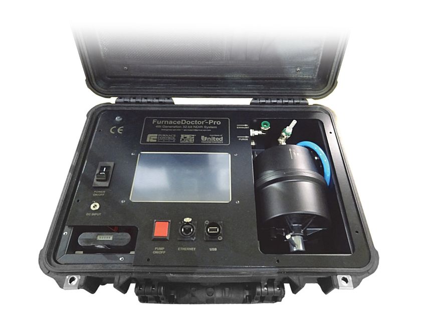
FurnaceDoctor®-Pro
                         V2.0
                     User Manual

CONNECT WITH US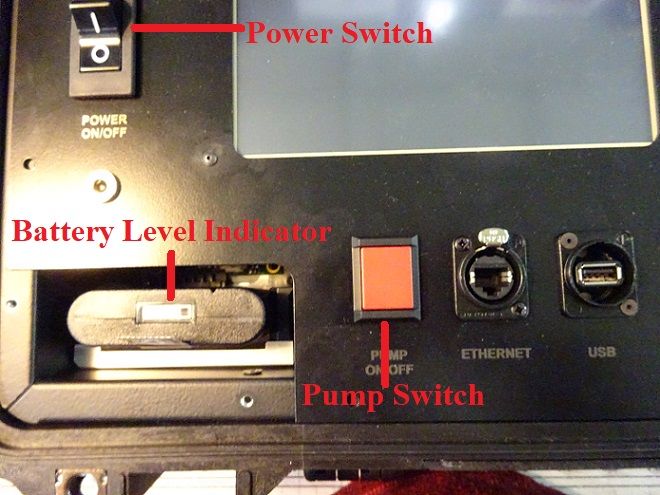
FurnaceDoctor®-Pro_rev003 – User Manual                                                         Page 2 of 87
        Manu103

MANUAL #: 103

 Revision # Revision Date                    Revision Description
 003        March 12, 2018
 002        February 1, 2015

COPYRIGHT(C)

No part of this publication may be reproduced, transmitted, transcribed, stored in a retrieval
system, or translated into any language or computer language, in any form or by any means,
electronic, mechanical, magnetic, optical, chemical, manual, or otherwise, without prior written
permission of United Process Controls Inc. (UPC-Marathon).

The information contained in this document is STRICTLY CONFIDENTIAL and
PROPRIETARY to UPC-Marathon, and shall not be: i) reproduced or disclosed in part or in
whole, ii) used for any design or manufacturing of heat treating and/or control equipment, or
any other purpose except for that which it is supplied under the terms of the Contract, unless
the express written authorization is obtained from UPC-Marathon.

Drawings and photographs included in the documentation are the property of UPC-Marathon,
and it is strictly forbidden to reproduce them, transmit them to a third party, or use them for
manufacturing and/or design of equipment. Sub-licensing of any technical information
contained in this Documentation is strictly forbidden under the terms of the Contract.

UPC-Marathon reserves the right to modify this document without prior notice.

DISCLAIMER:

The FurnaceDoctor®-Pro V2.0 is to be used by the industrial operator under his/her direction.
United Process Controls Inc. (UPC-Marathon) is not responsible or liable for any product,
process, damage or injury incurred while using the FurnaceDoctor®-Pro V2.0. United
Process Controls Inc. makes no representations or warranties with respect to the contents
hereof and specifically disclaims any implied warranties or merchantability or fitness for any
purpose.

TECHNICAL ASSISTANCE

For all questions or concerns regarding the operation of the FurnaceDoctor®-Pro V2.0,
please consult the last page of this manual for contact information.

Copyright © Upc-Marathon.                                     All rights to copy, reproduce and transmit are reserved.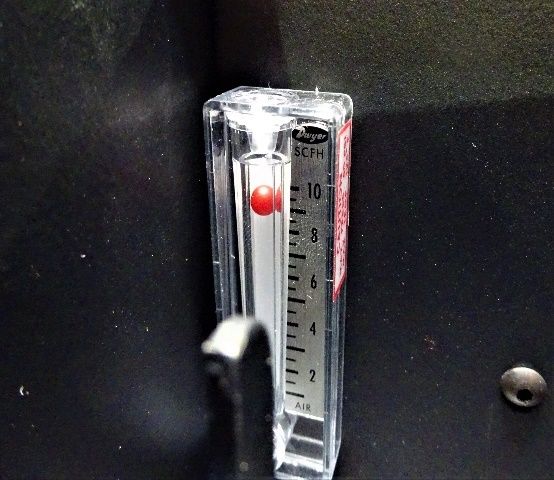
FurnaceDoctor®-Pro_rev003 – User Manual                                                                                         Page 3 of 87
        Manu103

Table of Contents

1      SAFETY .............................................................................................................................6
2      THEORY ............................................................................................................................7
          Why Infrared?........................................................................................................................... 7
          Endothermic Atmosphere ......................................................................................................... 7
          How Can the FurnaceDoctor®-Pro Help Me with My Generator? ............................................. 8
          So How Can the FurnaceDoctor®-Pro Help? ........................................................................... 9
          How Will the FurnaceDoctor®-Pro Help Me with My Furnace Atmosphere? ........................... 10
3      OPERATIONS.................................................................................................................. 11
          Precautions Before Operations:.............................................................................................. 11
          User Manual Specifics ............................................................................................................ 11
          Sample Gas ........................................................................................................................... 11
          Particles ................................................................................................................................. 12
          Humidity ................................................................................................................................. 12
          Liquids.................................................................................................................................... 13
          Entrained Oil .......................................................................................................................... 13
          Gas Sampling Ports ............................................................................................................... 13
4      INITIALIZING THE ANALYZER....................................................................................... 15
          Connecting the Gas Lines ...................................................................................................... 15
          Default Display ....................................................................................................................... 18
5      THE MENU SYSTEM ....................................................................................................... 19
          Accessing the Main Menu Screen .......................................................................................... 19
          Main Menu Available Options ................................................................................................. 20
6      I/R Gas Values ................................................................................................................ 21
          Selecting the Dew point, Calculation Modes ........................................................................... 21
          Furnace Mode Selection......................................................................................................... 22
          Generator Mode Selection...................................................................................................... 24
          ENDO and EXO Selection ...................................................................................................... 25
          Data Logging Preparation....................................................................................................... 26
          Enter Log I.D. ......................................................................................................................... 27
          Enter Log File Name .............................................................................................................. 28

Copyright © Upc-Marathon.                                                                  All rights to copy, reproduce and transmit are reserved.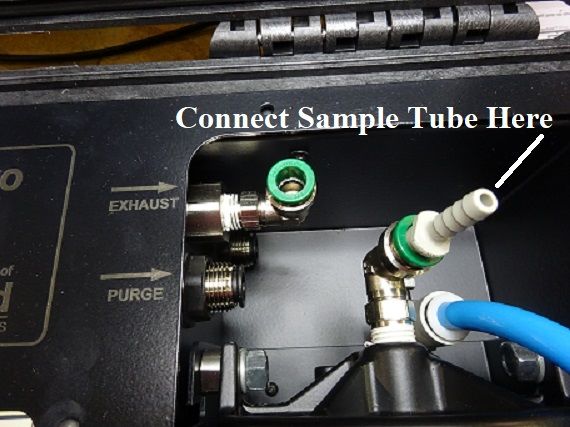
FurnaceDoctor®-Pro_rev003 – User Manual                                                                                       Page 4 of 87
        Manu103

          Enter Data Log Interval .......................................................................................................... 29
              Enter Additional Comments ............................................................................................... 31
              Insert USB Stick................................................................................................................. 33
              Start Data Logging ............................................................................................................. 34
              Stop Data Logging ............................................................................................................. 36
7      View Chart Icon .............................................................................................................. 39
          Stand Alone Chart Viewer ...................................................................................................... 39
          Viewing Log Files ................................................................................................................... 40
8      CALIBRATION................................................................................................................. 41
          Gas Requirements ................................................................................................................. 41
          Calibration: Span Gas Verification .......................................................................................... 42
          To Begin Calibration ............................................................................................................... 42
          Starting Calibration ................................................................................................................. 46
          Zero Calibration ...................................................................................................................... 46
          Span Calibration ..................................................................................................................... 50
          Restoring Factory Calibration ................................................................................................. 52
9      PROCESS CALCULATOR .............................................................................................. 54
          Accessing the Process Calculator .......................................................................................... 54
          Calculation Method Set to: Options ........................................................................................ 58
10     UTILITIES ........................................................................................................................ 59
              Utilities Configurable Options ............................................................................................. 59
              Date and Time ................................................................................................................... 60
              Configure I/R Screen ......................................................................................................... 62
              Configure I/R Screen, Page 1 Options Include ................................................................... 63
              Carrier Gas Selection Options ........................................................................................... 64
              Please Select Carrier Gas ................................................................................................. 64
              Configure I/R Screen, Page 2 Options Include ................................................................... 66
              Generator Mode Process Temperature .............................................................................. 67
              Gas Generator Selection ................................................................................................... 68
              Configure I/R Screen, Page 3 Options Include ................................................................... 70
11     BATTERY CHARGER ..................................................................................................... 71
              What’s Included? ............................................................................................................... 71
              Charging ............................................................................................................................ 72

Copyright © Upc-Marathon.                                                                All rights to copy, reproduce and transmit are reserved.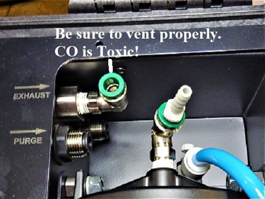
FurnaceDoctor®-Pro_rev003 – User Manual                                                                                      Page 5 of 87
        Manu103

12     ETHERNET SETUP ......................................................................................................... 72
              Accessing the Ethernet Setup ............................................................................................ 72
13     VNC Viewer ..................................................................................................................... 75
              What is VNC Viewer? ........................................................................................................ 75
              Example............................................................................................................................. 75
14     General Maintenance ..................................................................................................... 77
              Inspecting and Replacing the Filter .................................................................................... 77
15     TROUBLESHOOTING ..................................................................................................... 82
              How Can I Use the FurnaceDoctor®-Pro to Troubleshoot the Furnace? ............................ 82
              How Do I Interpret the Gas Values?................................................................................... 83
16     Frequently Asked Questions (FAQs) ............................................................................ 84
17     EQUIPMENT RATINGS ................................................................................................... 85
18     SPARE PARTS ................................................................................................................ 86
19     CUSTOMER SUPPORT .................................................................................................. 87

Copyright © Upc-Marathon.                                                                All rights to copy, reproduce and transmit are reserved.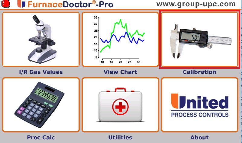
FurnaceDoctor®-Pro_rev003 – User Manual                                             Page 6 of 87
        Manu103

1        SAFETY

               ****CAUTION****
          Make sure the exhaust of the
      FurnaceDoctor®-Pro is properly vented

            ****WARNING****
    DO NOT CLOSE LID with CHARGER IN
         THE STORAGE POUCH
                   SCREEN CAN BE DAMAGED
              NOT COVERED BY WARRANTY
           Please read the instructions before operating the instrument.

     This instrument complies with accepted industrial safety standards.

    Do NOT operate this instrument with the internal top cover removed.

Copyright © Upc-Marathon.                         All rights to copy, reproduce and transmit are reserved.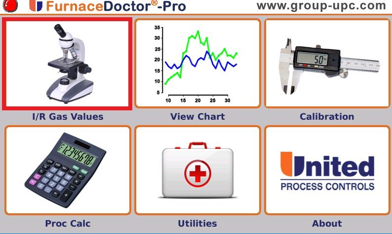
FurnaceDoctor®-Pro_rev003 – User Manual                                                          Page 7 of 87
        Manu103

2        THEORY
         Why Infrared?

Your new FurnaceDoctor®-Pro enhances process measurement methods and is an invaluable
troubleshooting tool. It also assures your customer that you can verify the process and your
existing oxygen probe. It not only answers the question “is that probe really working?” It
confirms that the gases in your process are within specification.

In cases of excess methane, the oxygen probe and the carbon calculation derived from it can
present misleading information. In situations like this I/R analysis is invaluable.

Whatever your reasons, the use of I/R analysis, and the FurnaceDoctor®-Pro will satisfy these
requirements.

Since most FurnaceDoctor®-Pro owners are either performing gas carburizing, or neutral
hardening in an endothermic atmosphere, or verifying exothermic atmospheres. The following
discussion will explain the meaning of the measured values.

         Endothermic Atmosphere

Endothermic atmospheres in use for these applications have this basic composition:

                      CO ≅ 20%           (carbon monoxide)
                      H2 ≅ 40%           (hydrogen)
                      CO2 ≅ Trace        (carbon dioxide)
                      CH4 ≅ Trace        (methane, usually from natural gas)
                      O2 ≅ Trace         (oxygen)
                      H2O ≅ Trace        (water vapor)
                      N2 = Balance       (nitrogen)

These ratios are typical whether you are producing gas by means of an endothermic generator
or using prepared gasses such as nitrogen and methanol. Ratios are slightly different if
propane is used rather than methane for the carrier gas.

Obviously, any increase in volume in one of the gasses means a decrease in one or more of
the other gasses. We often get asked the question “Why is my generator producing 20% CO,
but I am only measuring 17% at my furnace?” “It is even lower when I add ammonia!” One part
of the answer to this question is simple volumetric displacement. There is only room in the
furnace for 100% of the atmosphere!

Copyright © Upc-Marathon.                                      All rights to copy, reproduce and transmit are reserved.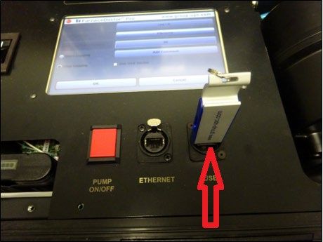
FurnaceDoctor®-Pro_rev003 – User Manual                                                          Page 8 of 87
        Manu103

         How Can the FurnaceDoctor®-Pro Help Me with My Generator?

The basic chemical reaction taking place in an endothermic generator is as follows:
Remember you are mixing gas and air together, heating it up, and passing these gases

                                       2CH4 + O2→ 2 CO + 4 H2
                                         Ignoring the nitrogen

through a nickel catalyst to produce the above described gas composition. The reaction takes
place in two stages:
    • First some of the methane burns with air and makes heat. The by-products of this
       combustion are H2O (water vapor), and CO2.
    • In the second stage, the remaining methane reacts with the CO2, and H2O. It becomes
       obvious that we want this reaction to be as complete as possible.

This is the reason for the nickel catalyst in the generator.

If the main air gas ratio is set somewhere between 2.7 and 2.85 parts air to 1-part gas, there
are two considerations:
     • The catalyst must be clean, and free from soot. If soot is present, the efficiency of the
        above reactions goes down.
     • You must have adequate temperature to keep the rate of the reactions high enough.

Copyright © Upc-Marathon.                                      All rights to copy, reproduce and transmit are reserved.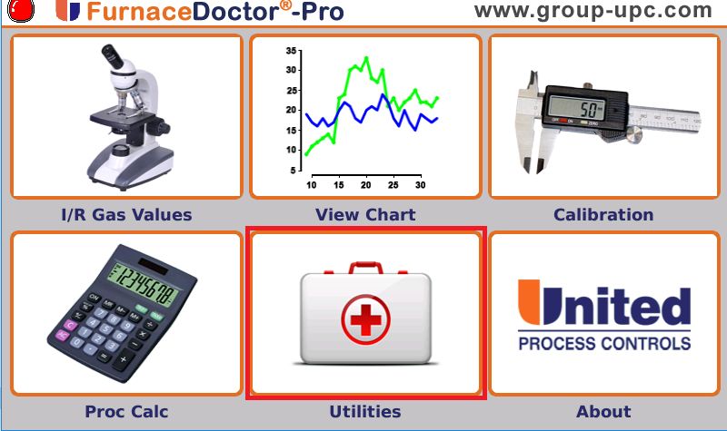
FurnaceDoctor®-Pro_rev003 – User Manual                                                         Page 9 of 87
        Manu103

         So How Can the FurnaceDoctor®-Pro Help?

First, by measuring the generator’s methane content you can determine whether the catalyst is
operating efficiently. .8% CH4 is generally the upper limit. Above this level,         it is possible
that the catalyst is laden with soot, or the catalyst is simply spent. Another indication of this
condition would be a high CO2, or dew point. The FurnaceDoctor®-Pro provides a convenient
way to obtain dew point, CO, CO2, and CH4.

Check to see that the basic gas composition is as expected.
  • CO should be around 20%.
  • Check the CH4 level and be sure that it is less than .8%.
  • Observe the CO2, and the dew point readings. Note the relationship between dew point,
      and CO2.

                                   Carbon Dioxide VS Dewpoint

                                                                     1.60
                                                                     1.40
                                                                              %Carbon Dioxide
                                                                     1.20
                                                                     1.00
                                                                     0.80
                                                                     0.60
                                                                     0.40
                                                                     0.20
                                                                     0.00
                            0    20       40        60   80   100

                                         Dewpoint

To obtain the desired dew point, adjustments are made to either your oxygen probe control
system, or the generator carburetor.

Copyright © Upc-Marathon.                                     All rights to copy, reproduce and transmit are reserved.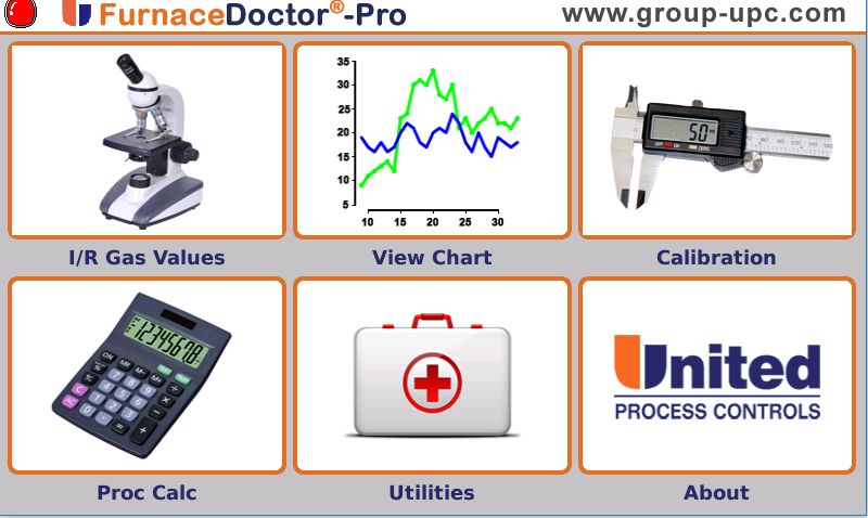
FurnaceDoctor®-Pro_rev003 – User Manual                                                          Page 10 of 87
        Manu103

         How Will the FurnaceDoctor®-Pro Help Me with My Furnace Atmosphere?

If you are using oxygen probes, the FurnaceDoctor®-Pro provides an independent, traceable
verification of your probes accuracy. It will also give you a more complete picture of what is
happening in your furnace atmosphere.

The primary reactions involved in carbon transfer are:

                                              2CO→ Cγ +CO2
                                            H2 + CO → Cγ + H2O

These reactions are assumed to be close to equilibrium. The theory behind this is that a
reaction sometimes called the water-gas reaction, is busy keeping the H2 and O2 in balance:

                                           CO + H2O ↔ CO2 +H2

The measurement of % Carbon in your atmosphere with an oxygen probe is based on the
assumption that the above is true.

CO → Cγ + ½ O2

Note that it is assumed that the primary mechanism of carbon transfer is CO dependent.
       What is really happening is that the ratio of CO to CO2 is a much more accurate means
of determining equilibrium carbon.

One potential problem is when CH4 is used as an enriching gas, once it enters the
     furnace, it decomposes - mostly near the hot catalytic surfaces in your furnace.

It may be replenishing depleted CO, based on equilibrium “rules”, it may be making soot
crumbs on your hearth, or it may be reacting directly with the surface of the material:

                                                  CH4→Cγ + 2H2

How much of the above reaction is happening is dependent on many variables, but primarily,
how much methane is present in your furnace. This reaction also happens faster at higher
temperatures but is still slow compared to the equilibrium reactions.

For example; at 1600 with an equilibrium carbon potential of .4%, and methane content of .5
the theoretical carbon potential is 0.44%. In reality, the effect is usually about 6/10 of what the
theoretical calculations deliver making the carbon potential closer to .42%. By contrast if we
were to increase the methane content to 5%, the actual carbon potential might be closer
to .6%, a significant difference!

Copyright © Upc-Marathon.                                        All rights to copy, reproduce and transmit are reserved.
FurnaceDoctor®-Pro_rev003 – User Manual Page 11 of 87
Manu103
Whether the work really ends up seeing this is dependent on several variables – governing
the rate of reaction, the surface area of the work and the level of saturation at the surface,
atmosphere circulation, etc.
3 OPERATIONS
Precautions Before Operations:
• Dew point of sampling gas must be lower than the ambient temperature to avoid water
contamination in the gas analyzer. If vapor is contained in the sampling gas, dew point
should be lowered to 0°C. Add a desiccant filter to the gas sample line if this is a
problem.
• Temperature of sampling gas should be within 0 to 50°C. Provide a means that
prevents entry of hot gas directly into the instrument.
• Absolute pressure of sampling gas should be 926 – 1024 mBar. Avoid flow or pressure
fluctuation during measurement. Observe the flow reading by viewing the provided
flowmeter.
• Avoid installing this instrument near an electrical unit (high frequency furnace or electric
welder) that generates electrical noise.
• Allow 20 minutes warm-up for stabilized readings.
User Manual Specifics
The User Manual has been created with a customer focus in mind. Certain aspects of various
sections have been designed specifically to provide the user with a visual indication of
technical functions of the various screens. UPC Inc. has developed a color-coded system of
identification in order to assist the technician while interfacing with the FurnaceDoctor®-Pro.
The associated Color-Code key is as follows:
• Yellow highlighting indicates a reference location on the screen
• Green highlighting indicates a specific implemented change
• Red highlighting indicates that a user touch, or parameter entry is required
Sample Gas
Copyright © Upc-Marathon. All rights to copy, reproduce and transmit are reserved.FurnaceDoctor®-Pro_rev003 – User Manual Page 12 of 87
Manu103
The condition of the sample must conform to the following requirements to ensure that the
performance of the product meets the stated technical specification. Contamination in the
sample cell, particularly on the internal cell windows, will cause an error in gas
readings.
Avoid degradation of the sample gas between the sample point and the sensor.
Eliminate any large volumes (filters) or restrictions.
Avoid sampling when large transients in the operation can occur. These can
cause pressure variations.
Maintain constant flow conditions.
Avoid the use of rubber compounds for the sample tubing (adsorption effects).
Particles
The gas to be measured must be well filtered. 100 % of 3 µm particles must be retained. The
analyzer has a large built in pre-filter. Check this filter before use, or at minimum once per
week. See section 16 “General Maintenance for filter maintenance.
Inspect the large pre-filter in the analyzer at least once a week. Verifying that the filter is clean
is the single most important maintenance check you can perform to protect your investment
and extend the operating life of the analyzer.
Humidity
Moisture in the gas must be adequately reduced. This means that the dew point of the gas
must be below the operating temperature of the FURNACEDOCTOR®-PRO. No moisture can
then condense in the IR benches.
Copyright © Upc-Marathon. All rights to copy, reproduce and transmit are reserved.FurnaceDoctor®-Pro_rev003 – User Manual Page 13 of 87
Manu103
Liquids
The sample gas must be free of any liquid.
Entrained Oil
The sample gas must be free of any contamination.
Gas Sampling Ports
In a large percentage of heat treating environments, we have found that the gas sample ports
are either plugged or leaking. Even if you can see into the port, and it appears unobstructed,
the port may leak somewhere behind the hot face of the refractory. This may cause the
sample to be drawn from between the brick, and the furnace shell, or even outside of the
furnace.
It is also necessary to keep the sample velocity high to quickly stabilize the CO2.
For this reason, we strongly recommend the use of a ceramic sample probe like the UPC
GST1-23-0.50 Sampling Tube. This will penetrate the furnace wall at least 2” past the hot face
of the refractory.
If you are unable to use a non-metallic probe and you are getting numbers that are not making
sense (i.e. extremely low CO values or high CO2) then try taking a sample from the oxygen
probe burn-off port (not the reference airport). Only use this method if no other working
port is available. This method will affect the probe reading.
Copyright © Upc-Marathon. All rights to copy, reproduce and transmit are reserved.FurnaceDoctor®-Pro_rev003 – User Manual Page 14 of 87
Manu103
Copyright © Upc-Marathon. All rights to copy, reproduce and transmit are reserved.FurnaceDoctor®-Pro_rev003 – User Manual Page 15 of 87
Manu103
4 INITIALIZING THE ANALYZER
*********** CAUTION **********
Connecting the Gas Lines
Connect one end of the sample tube to the analyzer inlet. Connect the other end to the furnace
sample port. Do not connect to a port with a lamb’s wool, or angel hair filter already installed.
Be sure to properly vent exhaust!
We strongly recommend a small diameter (½” id or less), ceramic sample tube that can be
inserted at least 2” past the refractory wall hot face to ensure an accurate sample.
Sample Tube Connection
Exhaust Port Connection
Turn on the power switch. Apply power to the analyzer for at least 20 minutes to allow the IR
cell temperature to stabilize. Depress the Pump button to start sampling.
Copyright © Upc-Marathon. All rights to copy, reproduce and transmit are reserved.FurnaceDoctor®-Pro_rev003 – User Manual Page 16 of 87
Manu103
Your FurnaceDoctor®-Pro is equipped with a battery monitor. When a battery level monitor
is low, it is time to charge your FurnaceDoctor®-Pro.
Battery Level Indicator
The default “I/R Gas Values” screen will illuminate, and pressing the Pump ON/OFF switch will
initialize the internal pump.
Manual entry fields are in white with orange boarders, live and calculated fields are in white.
Characteristic Fields are gray.
Default Screen
After 30 seconds gas values will be measured and displayed.
Ensure that sample flow is adequate. If you are sampling a generator keep the flow rate below
10 SCFH so you do not compress the gas, this can lead to inaccurate readings.
Copyright © Upc-Marathon. All rights to copy, reproduce and transmit are reserved.FurnaceDoctor®-Pro_rev003 – User Manual Page 17 of 87
Manu103
Flowmeter at ≤ 9 SCFH
Measurement begins approximately 1 min after start-up and is continuous after the process
temperature is entered. The unit will not correctly display O2 [mV], Carbon, or Dewpoint until
temperature is entered. The display shows the measured CO, CO2, CH4 values and calculated
theoretical carbon and dewpoint and expected sensor millivolts.
These calculated values are only valid if the actual process temperature is manually entered.
Copyright © Upc-Marathon. All rights to copy, reproduce and transmit are reserved.FurnaceDoctor®-Pro_rev003 – User Manual Page 18 of 87
Manu103
Default Display
The instrument’s default display is the I/R Gas Values screen. The carbon, dewpoint for the
measured CO, CO2, CH4 gasses and entered probe temperature can be viewed here.
Additionally, it displays calculated probe millivolts.
Default Display I/R Gas Values
The instrument will take at least 20 minutes from a cold start to display any meaningful
information. Ensure that sample flow is adequate!
Copyright © Upc-Marathon. All rights to copy, reproduce and transmit are reserved.FurnaceDoctor®-Pro_rev003 – User Manual Page 19 of 87
Manu103
5 THE MENU SYSTEM
Accessing the Main Menu Screen
The instruments default display is the I/R Gas Values screen.
“System Default Screen”
Touching the “Main Menu” button on the “System Default Screen” will take you to the system
main menu screen.
“System Main Menu Screen”
Copyright © Upc-Marathon. All rights to copy, reproduce and transmit are reserved.FurnaceDoctor®-Pro_rev003 – User Manual Page 20 of 87
Manu103
Main Menu Available Options
The following options are available from the Main Menu Screen:
• I/R Gas values – This is the display that you see when the instrument is first powered
up. Data includes CO, CO2, CH4, and user entered temperature. Based on the
temperature entry the CP%, C%, C+CH4%, sensor mV, and dew point are determined
in the “Configure I/R Screen”. The checked items will be displayed and logged.
• View Chart – Allows the user to view internally stored data on a graphical chart
• Calibration – This option allows you to calibrate the instrument to certified grade
gasses
• Proc Calc – Allows you to enter temperature, oxygen probe millivolts or CO, CO2, CH4,
H2, Alloy Factor, and CH4 Factor to compute carbon potential and dew point. You can
also enter the dew point and temperature to compute the above.
• Utilities - This allows you to calibrate the touch screen, set the date and time,
configure the I/R Gas Values screen, update firmware, review and reset accumulated
runtime counter, and set factory calibration reminder. This page is password protected.
• About - tells about software version, customer support and the members of United
Process Controls.
Copyright © Upc-Marathon. All rights to copy, reproduce and transmit are reserved.FurnaceDoctor®-Pro_rev003 – User Manual Page 21 of 87
Manu103
6 I/R Gas Values
Selecting the Dew point, Calculation Modes
If your display is not already on its default (I/R Gas Values) screen, then this can be
accomplished by selecting the “I/R Gas Values” Icon from the Main Menu Screen.
Main Menu Screen
The instrument will compute dew point using either a temperature-based calculation, used
when measuring furnace atmospheres where you can identify the process temperature, or a
simplified table look up method based on CO2 to be used when measuring the dew point of
endothermic generators.
Copyright © Upc-Marathon. All rights to copy, reproduce and transmit are reserved.FurnaceDoctor®-Pro_rev003 – User Manual Page 22 of 87
Manu103
Furnace Mode Selection
“Furnace Mode” dew point calculation can be selected by touching the “Change” button to the
right of the “Furnace Mode” field for measuring your endothermic generator.
Furnace Mode Selection
The “Furnace Mode” process temperature can be manually entered by touching the numerical
entry button “1,700”.
Numerical Entry Button
Upon touching the numerical entry button, a keyboard will appear on the display which will
allow the process temperature to be manually entered. Enter the numerical value, then touch
Ok.
Copyright © Upc-Marathon. All rights to copy, reproduce and transmit are reserved.FurnaceDoctor®-Pro_rev003 – User Manual Page 23 of 87
Manu103
Keyboard Entry for Process Temp
Dew Point calculations for endothermic conditions are only valid for temperatures of 1900 °F/
1038 °C or less.
Copyright © Upc-Marathon. All rights to copy, reproduce and transmit are reserved.FurnaceDoctor®-Pro_rev003 – User Manual Page 24 of 87
Manu103
Generator Mode Selection
To select the “Generator Mode” dew point calculation method, touch the
“Change” button to the right of the “Furnace Mode” field.
Furnace Mode Change
If you have the Generator Mode selected, it is not necessary to enter a process
temperature as the default value is 1680.
Generator Mode Change
Copyright © Upc-Marathon. All rights to copy, reproduce and transmit are reserved.FurnaceDoctor®-Pro_rev003 – User Manual Page 25 of 87
Manu103
If “Generator Mode” is selected, the correct carrier gas for your process must
also be selected. Please refer to the Utilities Section 8.6 of this user manual for instructions
on selecting the carrier gas.
ENDO and EXO Selection
If ENDO and EXO Gas has been selected under the Utilities Icon Page 2 Tab, then ENDO or
EXO mode must be selected via the I/R Gas Values Screen.
“ENDO Change”
To change from ENDO to EXO touch the Change button to the right of the “ENDO” or “EXO
Field”. Touching the change button will switch between the 2 modes.
“EXO Change”
Copyright © Upc-Marathon. All rights to copy, reproduce and transmit are reserved.FurnaceDoctor®-Pro_rev003 – User Manual Page 26 of 87
Manu103
Data Logging Preparation
From the I/R Gas Values Screen, locate and touch the “Change” button to the left of the
Logging: On/Off Selection field.
Logging On/Off Button
Touching the Logging: On/Off “Change” button will result in the following Data Log
Identification Screen being displayed.
“Log ID Screen”
Copyright © Upc-Marathon. All rights to copy, reproduce and transmit are reserved.FurnaceDoctor®-Pro_rev003 – User Manual Page 27 of 87
Manu103
Enter Log I.D.
To enter the Log I.D. simply touch the “Log I.D.” field.
“Log ID Field”
The Log I.D. field allows you to enter an identifier that will be automatically logged with the I/R
data.
For example; you may identify the log file by typing “Furnace 1” in the second line of the
keyboard screen, then touch Ok in the bottom left corner of the screen.
“Log ID Entry”
Copyright © Upc-Marathon. All rights to copy, reproduce and transmit are reserved.FurnaceDoctor®-Pro_rev003 – User Manual Page 28 of 87
Manu103
Notice that the Log I.D. Field has changed in accordance with the text that was entered using
the keyboard for Log I.D. entry
“Furnace 1 Entry”
Enter Log File Name
Touch the “Log File Name” field button.
“Log Filename Selection”
Enter the Filename of your choosing, using the Log Filename keyboard entry screen, then
touch “Ok” in the bottom left corner of the screen.
Copyright © Upc-Marathon. All rights to copy, reproduce and transmit are reserved.FurnaceDoctor®-Pro_rev003 – User Manual Page 29 of 87
Manu103
“Log File Name Entry”
Enter Data Log Interval
The “Data Log Interval should be selected next, by touching the orange box to the right of the
“Data Log Interval (secs)” field.
“Data Log Interval” Selection
Data Log Interval has been designed to record data points based on the numerical value in
seconds entered in this field. Interval range is from 30 – 3600 Seconds.
Copyright © Upc-Marathon. All rights to copy, reproduce and transmit are reserved.FurnaceDoctor®-Pro_rev003 – User Manual Page 30 of 87
Manu103
In the image above, a snap-shot of data will be captured every 30 seconds.
Alternatively, if a value of 60 is entered in this field then a snap-shot of data will be captured
every minute or once every 60 seconds.
Enter the numerical value in the Data Log Interval (secs) screen that represents the time in
seconds that data samples will be captured, then touch “Ok”.
“Data Interval” Entry Screen
Copyright © Upc-Marathon. All rights to copy, reproduce and transmit are reserved.FurnaceDoctor®-Pro_rev003 – User Manual Page 31 of 87
Manu103
Enter Additional Comments
The “Add Comment” field has been added to allow the operator the ability to annotate any
pertinent details to the Data Log file.
Touch the “Add Comment” button to bring up the add comments entry screen.
“Add Comment” Button
Touch the “Enter Text” button.
“Enter Text” Button
Here you can add any special notes pertaining to the Data Log. First enter text, then touch Ok.
Copyright © Upc-Marathon. All rights to copy, reproduce and transmit are reserved.FurnaceDoctor®-Pro_rev003 – User Manual Page 32 of 87
Manu103
“Add Comment” Keyboard Screen
Notice that the entered text is now being displayed in the “Notes” field on the “Add Comments”
screen. Touch the Close button at the bottom of the screen.
“Add Comment” Close Button
The Data Log I.D. screen will appear reflecting the changes that were entered in sections 6.4 –
6.8 above, Touch Ok.
Copyright © Upc-Marathon. All rights to copy, reproduce and transmit are reserved.FurnaceDoctor®-Pro_rev003 – User Manual Page 33 of 87
Manu103
Data Log I.D. Reflected Changes
You will be returned to the Default Screen (Gas IR Values).
Default Screen
Insert USB Stick
Copyright © Upc-Marathon. All rights to copy, reproduce and transmit are reserved.FurnaceDoctor®-Pro_rev003 – User Manual Page 34 of 87
Manu103
To start data logging insert the factory configured CQI9 compliant USB flash drive in to the top
of the FurnaceDoctor®-Pro. The Furnace Doctor Firmware Update Procedure has been
included and is on the USB stick provided with your purchase.
Insert USB Stick
Compatible USB FLASH Memory Sticks:
• Dane Electric (DA-ZMP-02G-CA-W1-R)
• PQI Mr. Flash U172 (Model # BB55-B1G3-0221)
• Corsair (Model # CMFUSBSF2.0-128)
• Viking Interworks (Model # USB00256L2)
• Kingston DataTraveler (Model # DTI/1GBKR)
• PNY Technologies (Attaché 256 or 512)
• Lexar JumpDrive
• Viking (Model # USB0032L)
• Sony (Model # Microvault)
• Dell (Model # Memory Key)
Start Data Logging
Upon start-up the Furnace Doctor Pro will display, by default, the I/R Gas Values Screen.
Locate the “Logging: OFF” field and touch the “Change” button to the right.
Copyright © Upc-Marathon. All rights to copy, reproduce and transmit are reserved.FurnaceDoctor®-Pro_rev003 – User Manual Page 35 of 87
Manu103
“Default Screen” = I/R Gas Values
Locate the “Use USB” field and touch the small “Change” button to the left., then touch the
circle to the left of the “Start Logging” text, and finally touch Ok.
Touch the “Use USB Device” Button
You will be prompted with a reminder to Please Insert the USB memory stick. Ensure the USB
Memory Stick has been installed, then Touch Ok inside the pop-up, then touch Ok in the
bottom of the screen.
Copyright © Upc-Marathon. All rights to copy, reproduce and transmit are reserved.FurnaceDoctor®-Pro_rev003 – User Manual Page 36 of 87
Manu103
“Please Insert USB”
This will return you to the I/R Gas Values screen. The neon green indicator box to the left of
the “Logging: ON” text will illuminate.
“Logging On” Indicator
Stop Data Logging
To stop Data Logging push the orange “Change” button to the right of the “Logging: ON” text.
Copyright © Upc-Marathon. All rights to copy, reproduce and transmit are reserved.FurnaceDoctor®-Pro_rev003 – User Manual Page 37 of 87
Manu103
“Logging: ON” Change button
The following screen will be displayed. Touch on the circle to the left of “Stop Logging” and
then touch OK.
“Stop Logging”
You will be returned to the I/R Gas Values Screen, notice that Logging has now been turned
off.
Copyright © Upc-Marathon. All rights to copy, reproduce and transmit are reserved.FurnaceDoctor®-Pro_rev003 – User Manual Page 38 of 87
Manu103
“Logging: Off” Indicator
Remove the USB drive and insert into your PC to read the data of the encrypted file on the
standalone chart viewer.
Copyright © Upc-Marathon. All rights to copy, reproduce and transmit are reserved.FurnaceDoctor®-Pro_rev003 – User Manual Page 39 of 87
Manu103
7 View Chart Icon
Stand Alone Chart Viewer
Your FurnaceDoctor®-Pro is equipped with a built-in memory data logging system. Data on
all gas values is stored on 30-3,600 second intervals and is available for review from your PC
on our Stand-Alone chart viewer by touching the View Chart Icon on the Main Screen.
Log data is stored internally or on an industry standard USB memory stick.
File types are encrypted and are easily read by our Stand-Alone chart viewer program.
Stand Alone Chart Viewer
Data saved will include time, date, Log Id, CO, CO2, CH4, and user entered temperature.
Expected O2mv, dew point, %Carbon, will be determined in the “Configure I/R Screen”. The
checked items will be data logged. (See Utilities).
Copyright © Upc-Marathon. All rights to copy, reproduce and transmit are reserved.FurnaceDoctor®-Pro_rev003 – User Manual Page 40 of 87
Manu103
Viewing Log Files
Viewing and printing of the data log files collected by the FurnaceDoctor®-Pro Gas Analyzer
requires installation of the “FDLowView” software program.
Please follow the instruction included on the USB stick to install the “FDLowView” on a
Windows computer
Running the installation software required for this program requires the operator to have
administrator rights for the computer that the “FDLowView” program is being installed on.
“Chart Viewer”
Copyright © Upc-Marathon. All rights to copy, reproduce and transmit are reserved.FurnaceDoctor®-Pro_rev003 – User Manual Page 41 of 87
Manu103
8 CALIBRATION
Gas Requirements
You may calibrate your unit with certified grade span gas, and nitrogen. If you have plant
nitrogen available be sure to regulate it to approximately 1 PSI.
Span bottle gas must have a bottle top regulator that will be capable of regulation at 1 PSI.
Use only dual stage regulators for any calibration gas.
Be sure that your gas supplier provides you with a certified analysis of the gas in the bottle!
Valid ranges for span gas are:
CO 20 - 25.0%
CO2 .7 - 1.0%
CH4 8 - 15.0%
H2 40%
N2 balance
It is recommended that you select span gas with values approximately 20% higher than the
typical observed process value. Span gas values may be higher, or lower, but should not
exceed the ranges of the measuring cells.
Maximum cell ranges are:
CO 30%
CO2 2%
CH4. 15%
Be sure to keep the second stage regulator pressure around 1-2 PSI. Your FurnaceDoctor®-
Pro is equipped with good internal pressure regulation, but too much pressure may override
the regulator’s ability to control the pressure in the cells.
It is important to understand I/R cells are very pressure sensitive by nature. Realize that for a
given species of gas there are more molecules of that gas present in a cell with a pressure of
1.5 PSI., than in a cell with a cell pressure of .5 PSI. This will lead to measurement error if the
unit is calibrated at a high pressure, and then applied to low pressure measurements.
You may observe this phenomenon by closing off the exhaust of the instrument while
measuring a furnace. Note the quick rise in the CO value.
It is recommended that the zero condition of the analyzer is checked and adjusted if necessary
before any measurements are made. The zero check is more important than a span check if
only nitrogen is available.
Copyright © Upc-Marathon. All rights to copy, reproduce and transmit are reserved.FurnaceDoctor®-Pro_rev003 – User Manual Page 42 of 87
Manu103
Calibration: Span Gas Verification
Connect the span bottle to the instrument and check the analyzer span on a weekly basis. If
the instrument measures the span bottle within 2% of the analyzed values on the bottle, it is
not necessary to calibrate the instrument.
If calibration is required do it in the environment that the instrument will be used in. If you
calibrate the instrument in an office that is 70 °F, and then go use the instrument in a 110 °F
heat treat, you will probably experience some error in measurement.
To Begin Calibration
The procedure for Span gas values only needs to be performed when a new span bottle is to
be used.
Touch the Main Menu button from the default “I/R Gas Values: screen.
Touch Main Menu from Default Screen
From the Main Menu Screen, touch the Calibration Icon to select calibration Mode.
Copyright © Upc-Marathon. All rights to copy, reproduce and transmit are reserved.FurnaceDoctor®-Pro_rev003 – User Manual Page 43 of 87
Manu103
Main Menu Screen
The Calibration screen will open and the “Span” Gas Values will need to be checked to verify
that the numerical values under the “Value” heading match the “Actual Concentration (Mole %)
values as seen on the Vendor’s Gas Analysis Certificate.
“Calibration Screen”
Copyright © Upc-Marathon. All rights to copy, reproduce and transmit are reserved.FurnaceDoctor®-Pro_rev003 – User Manual Page 44 of 87
Manu103
Certificate of Analysis
Visual comparison between the current cylinder in use, Certificate of Analysis Actual
Concentration (Mole %) and the Gas Analyzers’ Calibration Screen indicates a numerical
discrepancy between the current value shown on the Gas Analyzer in the “Value” field for
%CO, %CO2, and %CH4, and these values will need to be adjusted to match the Actual
Concentration (Mole %) values shown on the Certificate of Analysis.
Touch the orange button containing the numerical value to allow for modification next to its
corresponding gas type. For demonstration purposes we will be focusing on the %C02
Copyright © Upc-Marathon. All rights to copy, reproduce and transmit are reserved.FurnaceDoctor®-Pro_rev003 – User Manual Page 45 of 87
Manu103
%CO2 Value Entry Button
The %CO, %CO2, and %CH4 “Value Fields can be manually changed by touching the orange
buttons under the “Value” field next to the corresponding gas type but must be changed one at
a time. For demonstration purposes, we will focus on the %CO2 number.
Using the keyboard enter the % CO2 (Carbon Dioxide) Actual Concentration (Mole %) value
obtained from the Certificate of Analysis, then touch “Ok”.
%CO2 Keyboard Entry Screen
Copyright © Upc-Marathon. All rights to copy, reproduce and transmit are reserved.FurnaceDoctor®-Pro_rev003 – User Manual Page 46 of 87
Manu103
Notice the %CO2 “Value” field has changed. The corresponding “values” for %CO, and %CH4
can also be changed to match the Actual Concentration (Mole %) value as seen on the
Certificate of Analysis for the current cylinder in use by adhering to paragraphs 9.3.7 & 9.3.8 of
this manual.
Changed %CO2 Value
Starting Calibration
To prevent over pressurizing during calibration, please adhere to the following:
• Decrease regulator pressure by turning the regulator control knob counter clockwise.
• Connect the tubing to the inlet port of the analyzer.
• Do not turn on the analyzer pump.
• Open the shut-off valves on the gas cylinder. There will be a main shutoff on the top of
the cylinder and usually a smaller one on the outlet side of the regulator.
• Slowly turn the regulator control clockwise while observing the small flow meter near the
bottom of the large analyzer filter.
• Stop the adjustment so that you are seeing a mid-scale indication on the flow meter, but
ensuring that you do not over pressurize the analyzer by exceeding a SCFH reading of
> 10.
Zero Calibration
Always perform a zero calibration before you perform a span calibration. It is recommended
that the zero state of the analyzer should be checked before any measurement is made.
Connect and turn on the nitrogen following the above procedure. Touch the Zero button.
Copyright © Upc-Marathon. All rights to copy, reproduce and transmit are reserved.FurnaceDoctor®-Pro_rev003 – User Manual Page 47 of 87
Manu103
Touch Zero Button
Immediately after Touching zero you will see a pop-up as viewed here. verify that the Zero Gas
is connected, adjust flowmeter to mid-scale indication SCFH, using caution to not exceed 10
SCFH as read on the flow meter.
Calibration Gas Ready
You will receive another prompt, reminding you to connect zero gas.
Copyright © Upc-Marathon. All rights to copy, reproduce and transmit are reserved.FurnaceDoctor®-Pro_rev003 – User Manual Page 48 of 87
Manu103
Connect Zero Gas Prompt
Verify that the Nitrogen (Zero Gas) has been connected to the Gas Analyzer’s “Sample In” Port
and gas flow has been properly adjusted to mid-scale indication on the flow meter, press OK to
start the calibration.
The orange Zero button in the Calibration Field will change to a 120 second count-up timer.
Notice the “Readings numbers at start of calibration.
Zero Calibration Count-Up Timer
When the counter has finished counting to 120, you will receive another on-screen prompt,
informing you that the Calibration data has been saved, touch Ok.
Copyright © Upc-Marathon. All rights to copy, reproduce and transmit are reserved.FurnaceDoctor®-Pro_rev003 – User Manual Page 49 of 87
Manu103
Calibration Data are Saved
Upon visual inspection of the “Span” and the “Reading” columns you should see numbers in
very close proximity to those viewed here.
After Zero Calibration Readings
Disconnect the Nitrogen (Zero) gas supply and connect the Span Gas, the Zero Gas
Calibration is now complete.
Copyright © Upc-Marathon. All rights to copy, reproduce and transmit are reserved.FurnaceDoctor®-Pro_rev003 – User Manual Page 50 of 87
Manu103
Span Calibration
Touch the orange Span Gas button in the Calibrate field.
Touch Span
Immediately after Touching Span you will see a pop-up as viewed here, verify that the Span
Gas is connected, adjust flowmeter to mid-scale SCFH, using caution to not exceed 10 SCFH,
then touch Ok inside the pop-up window.
Span Gas Ready?
Copyright © Upc-Marathon. All rights to copy, reproduce and transmit are reserved.FurnaceDoctor®-Pro_rev003 – User Manual Page 51 of 87
Manu103
Re-verify that the Span Gas has been connected to the Gas Analyzer’s “Sample In” Port and
gas flow has been properly adjusted to mid-scale on the flow meter, press OK to start the
calibration.
Connect Span Gas Prompt
The orange Span button in the Calibration Field will change to a 120 second count-up timer.
Span Gas Count-up Timer
Copyright © Upc-Marathon. All rights to copy, reproduce and transmit are reserved.FurnaceDoctor®-Pro_rev003 – User Manual Page 52 of 87
Manu103
Once the unit has counted-up to 120 the calibration is complete, and you will see another pop-
up window indicating that the “Span” Gas calibration data has been saved, touch Ok inside of
the pop-up window.
Expected Readings
You can now return to the I/R Gas Values screen. The instrument should read the values in
the bottle within 2% of the cell range. (I.e. 25% CO should be +/- .5% CO. or 24.5 – 25.5).
I/R Gas Values After Calibration
Annual Factory Calibration is suggested. Retain original box and custom packing foam for
return shipment to UPC. Annual factory calibration will ensure your analyzer performs at a high
degree of accuracy throughout its life.
Restoring Factory Calibration
Copyright © Upc-Marathon. All rights to copy, reproduce and transmit are reserved.FurnaceDoctor®-Pro_rev003 – User Manual Page 53 of 87
Manu103
If you wish to restore the calibration performed at the factory then touch the Restore Factory
Cal. button.
Restoring Factory Calibration
You will be prompted with “Are You Sure you want to restore factory calibration?” Touch OK
on the dialog box and the last factory calibration data will be restored
Restore Factory Calibration Prompt
You will see this screen next. Touch Ok to complete the restoration of factory calibration.
Copyright © Upc-Marathon. All rights to copy, reproduce and transmit are reserved.FurnaceDoctor®-Pro_rev003 – User Manual Page 54 of 87
Manu103
Factory Calibration Restored
When you send your analyzer into United Process Controls Inc. Corp. for calibration, the
calibration data, and the factory calibration date are entered and stored in the analyzer’s
memory, and is password protected.
9 PROCESS CALCULATOR
Accessing the Process Calculator
Touch the “process calculator” icon on the Main Menu Screen.
Copyright © Upc-Marathon. All rights to copy, reproduce and transmit are reserved.FurnaceDoctor®-Pro_rev003 – User Manual Page 55 of 87
Manu103
Main Menu, Process Calculator Icon
This feature has several options for computing carbon potential, dew point, and probe
millivolts.
“Process Calculator” Screen
Input fields include, the carbon monoxide percentage- %CO, the carbon dioxide percentage-
%CO2, the methane percentage- %CH4, the hydrogen percentage- %H2, and °F or °C
temperature.
To change from °F to °C, touch the “°F” button. Touching the °C button will change it back to
°F.
Copyright © Upc-Marathon. All rights to copy, reproduce and transmit are reserved.FurnaceDoctor®-Pro_rev003 – User Manual Page 56 of 87
Manu103
Changing form °F to °C
Other inputs are CO [%], CO2 [%], CH4 [%], H2 [%], Alloy Factor [%], CH4 Factor [%], O2 [mV],
and DPT [°F].
The CH4 Factor is a process factor that corrects for the catalytic effect that is happening in the
furnace from free CH4. 0 turns this feature off.
To change any of the input values, touch the associated Button. For example; let’s assume
that we need to modify the CO [%] value from 20 to 21. The following steps will provide clear
instruction on how this is accomplished.
Touch the orange change value button associated with the input parameter that needs to be
modified. For demonstration purposes, the C0 [%] field will be changed.
“CO [%]” Change Value
The CO [%] value entry screen will open immediately, enter the new value in the space
provided. For this example, the new value to be entered is “21”. Touch “Ok”.
Copyright © Upc-Marathon. All rights to copy, reproduce and transmit are reserved.FurnaceDoctor®-Pro_rev003 – User Manual Page 57 of 87
Manu103
CO [%] Value Entry Keyboard
Notice that the CO [%] value has now changed to 21.00. To perform the calculation based
on the new value entered, touch calculate.
“Calculate”
Notice that the Calculated values, CP atm [%], C [%], Sat. C [%], and O2 [%] have been
recalculated based upon the new value of 21 that was entered in the CO [%] field.
Copyright © Upc-Marathon. All rights to copy, reproduce and transmit are reserved.FurnaceDoctor®-Pro_rev003 – User Manual Page 58 of 87
Manu103
“New Calculations”
All input values can be changed by following this procedure as outlined in Paragraphs 8.1.7
thru 8.1.11 of this Manual.
Calculation Method Set to: Options
Use Gas Input
By entering the CO, CO2, CH4, Alloy Factor [%], CH4 Factor [%] and process temperature, the
O2MV, DPT, CP atm, %C, %C+CH4, Sat. %C, and % Oxygen will be computed. Touch the
CALCULATE button to calculate.
Use mV Input
By entering the oxygen probe millivolts, Alloy Factor [%], CH4 Factor [%] and process
temperature, the DPT, CP atm, %C, %C+ch4, Sat. %C, and % Oxygen will be computed. CO2
is also calculated. Changing the % CO will calculate the %H2. This will change the calculated
DPT, CP atm, %C, and % C+ ch4. Touch the CALCULATE button to calculate.
Use DPT Input
By entering the dew point (DPT), Alloy Factor [%], CH4 Factor [%] and process temperature
the O2MV, CP atm, %C, %C+ch4, Sat. %C, and % Oxygen will be computed. CO2 is also
calculated. Changing the %CO will calculate the %H2. This will change the calculated, O2MV,
CP atm, %C, %C+ch4. Touch the CALCULATE button to calculate.
Copyright © Upc-Marathon. All rights to copy, reproduce and transmit are reserved.You can also read