Using Unmanned Aerial Vehicle in 3D Modelling of UniCITI Campus to Estimate Building Size
←
→
Page content transcription
If your browser does not render page correctly, please read the page content below

Journal of Physics: Conference Series

PAPER • OPEN ACCESS

Using Unmanned Aerial Vehicle in 3D Modelling of UniCITI Campus to
Estimate Building Size
To cite this article: M. Saifizi et al 2021 J. Phys.: Conf. Ser. 1962 012057

View the article online for updates and enhancements.

                                 This content was downloaded from IP address 46.4.80.155 on 13/09/2021 at 10:20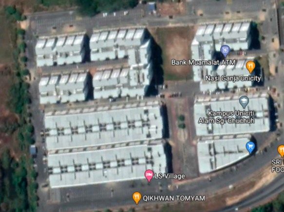
The 1st International Conference on Engineering and Technology (ICoEngTech) 2021          IOP Publishing
Journal of Physics: Conference Series            1962 (2021) 012057 doi:10.1088/1742-6596/1962/1/012057

Using Unmanned Aerial Vehicle in 3D Modelling of UniCITI
Campus to Estimate Building Size

                     M. Saifizi1,*, N. Syahirah1, Wan Azani Mustafa1, Hasliza A Rahim2, Mohd Wafi
                     Nasrudin2
                     1Faculty
                            of Electrical Engineering Technology, Universiti Malaysia Perlis, Malaysia
                     2Faculty
                            of Electronic Engineering Technology, Campus Pauh Putra, University of Malaysia Perlis,
                     02600 Arau, Perlis, Malaysia
                     saifizi@unimap.edu.my

                     Abstract. The drone mapping has a huge potential for numerous sectors including construction,
                     agriculture, mining, infrastructure inspection and real estate. Drones are used as assisting tools
                     in civil applications for large-scale aerial mapping of buildings, which is a difficult task for
                     surveyors to do because of the unreachable access area, time consuming, and expensive due to
                     limited resources and equipment. To address this issue, this paper introduces UAV-based
                     mapping. Furthermore, when flying from a different flight plan, the UAV will capture and collect
                     visual images. Then, the image from drone was process in Agisoft Metashape software to
                     generate a 3D model of building. This process will go through several steps to analyze which
                     method for capturing images can produce high-quality 3D mapping. The research results of this
                     project are to determine which photogrammetry technique can generate a high quality of 3D
                     mapping with accurate and fast.

        Keywords: UAV Mapping, 3D Model, Agisoft Metashape.

1.0 Introduction
Unmanned aerial vehicles known as UAV are an aircraft that was designed to operate with no pilot on
board. Recently, the unmanned aerial vehicle (UAV) has emerged as the most advanced technology
developed, mapping, topographical surveys, remote sensing studies, and providing an ideal platform for
aerial photography. [1-3]. Furthermore, UAV is used to determine the slope mapping, modelling of
building or urban cities, forest-fire monitoring, road monitoring, vehicle detection, disaster management
and mapping urban and suburban areas [4-6]. UAV photogrammetry is a new photogrammetric
measuring tool that combines close-range photogrammetry, aerial mosaic imaging, and terrestrial
photogrammetry [7-10]. Aerial photographs can be used to create planimetric and topographic maps
with varying degrees of accuracy. On the other hand, it is a component of the geomatic programme used
to calculate and chart the earth's surface. In addition, it introduced a real-time and automatic application
and is a low-cost alternative compared to traditional manned aerial photogrammetry [11-16]. Thus, these
papers focus to analyze the accuracy of measurements in 3D model building Agisoft Metashape software
from UAV mapping from different flight paths.

2.0 Methodology
The pilot study's workflow included the use of an unmanned aerial vehicle (UAV) called the DJI Mavic
Pro to capture all aerial images. The area of study is located at UniCITI Alam campus, UniMAP Sungai
Chuchuh, Padang Besar, Perlis. The selected building for this research is the 3 story shop lot known as
Block S4 as mentioned in Figure 2.
              Content from this work may be used under the terms of the Creative Commons Attribution 3.0 licence. Any further distribution
              of this work must maintain attribution to the author(s) and the title of the work, journal citation and DOI.
Published under licence by IOP Publishing Ltd                          1
The 1st International Conference on Engineering and Technology (ICoEngTech) 2021 IOP Publishing
Journal of Physics: Conference Series 1962 (2021) 012057 doi:10.1088/1742-6596/1962/1/012057
Figure 1: Flowchart representing automatic building generation using UAV
(a) (b)
Figure 2: Coverage area of study (a) Campus area (b) S4 building
2.1 UAV flight plan and image collection
The DJI Mavic Pro drone is equipped with high quality built-in camera with 12 Megapixels of
resolution, GPS/IMU, stabilizing system, electronic compass and good battery life performance.
Before flight, UAV should do the calibration process. Equipment such as UAVs, remote controllers,
and computers must be tested to ensure proper operation in order to avoid crashes and system failure
due to malfunction. The data collection by the UAV differs by the type of flight path. In this project,
two flight plans were developed using Drone Harmony application that can be accessed from a
smartphone or laptop. Following that, the mapping area is chosen, and a flight plan or waypoint is
generated based on the size of the area. This project covers one acre, and the flight attitude is set at
98 feet (30 meters) above the ground. Other advanced settings include flight direction, flight speed
during mapping, starting waypoint, obstacle avoidance, and front and side overlaps set to 80 percent
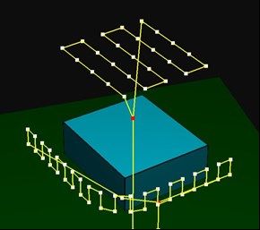
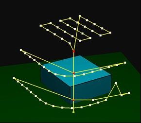
and 70 percent, respectively. Figure 3 depicts two different flight plans.
2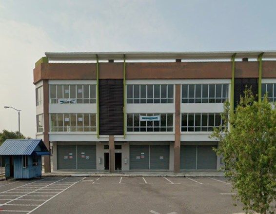
The 1st International Conference on Engineering and Technology (ICoEngTech) 2021          IOP Publishing
Journal of Physics: Conference Series            1962 (2021) 012057 doi:10.1088/1742-6596/1962/1/012057

                                 (a)                                       (b)

        Figure 3: Two flight plans for mapping building (a) Horizontal path (b) Vertical Path

   2.2 Image processing and 3D model
   The UAV collected raw images from two flight plans and the images were uploaded into Agisoft
   Metashape software to go through image processing part and generated in the 3D model. The first
   stage-loading photos to Metashape, followed by align photo, build dense point cloud, build mesh,
   build texture and build orthomosaic. Next, at align photo stage, the software refines the camera
   position for each photo and builds the point cloud model. The accuracy is set to the highest; the
   higher accuracy helps to obtain more accurate camera position estimates. After dense point cloud has
   been reconstructed, it is possible to generate a polygonal mesh model based on the dense cloud data.
   In mesh dialog, the surface type is selected to arbitrary, source data are from dense cloud, the polygon
   count is set to medium. To generate 3D model texture, the mapping mode in build texture dialog is
   set to generic, bending mode mosaic, texture count is set to 4096 x 1. Last stage is build orthomosaic.
   Orthomosaic export is normally used for generating of high imagery based on the source photos and
   reconstructed model as shown in Figure 4.

               Figure 4: Building outputs generated after image processing (a) 3D model building (b)
                                               Orthomosaic image

   2.3 Measure Building
   The building is measured using the scale bar, the measuring tool in software as shown in Figure 5.
   The experimental study results will determine the accuracy of measurement between 2 building from
   horizontal and vertical flight path thus can decide which flight path is suitable for mapping and
   produce a 3D model of building with accurate data measurement. The qualitative are done by

                                                     3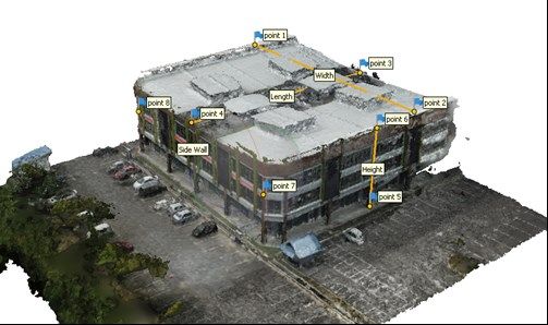
The 1st International Conference on Engineering and Technology (ICoEngTech) 2021          IOP Publishing
Journal of Physics: Conference Series            1962 (2021) 012057 doi:10.1088/1742-6596/1962/1/012057

   analysing the quality of the generated 3D model of building. Meanwhile, quantitative analysis is
   performed using error. The error is conducted using the equation shown in Equation 1.

where,
n1 = measured value
n2 = actual values
N = total number of data

                         Figure 5: Measuring building with tools in software.

3.0 Results and Discussion
In this study, the block S4-building measurements were taken according to the methodology explained.
3D models that have generated in the Agisoft Metashape software from horizontal and vertical path was
measured to find the accuracy of measurements between the actual value and measured values. The
results obtained from the UAV mapping were compared with the actual measurement from AutoCAD
drawing plan, as shown in Figure 6 and Figure 7. The accuracy is analysed based on the calculation of
the error between the two models of building.

                        Figure 6: 3D measurements from software (horizontal)

                                                    4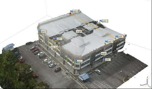
The 1st International Conference on Engineering and Technology (ICoEngTech) 2021          IOP Publishing
Journal of Physics: Conference Series            1962 (2021) 012057 doi:10.1088/1742-6596/1962/1/012057

                            Table 1: Measurement of horizontal mapping data

                                    Actual Value        Measured Value
                    Building                                                    Error
                                        (m)                  (m)
                  Parameter
                   Length                34.1                 33.44              0.66
                    Width                37.8                 37.77              0.03
                    Height                13                  12.17              0.83
                  Wall Length            33.6                 33.45              0.15

The data in Table 1 and Table 2 show the positive differences from AutoCAD drawing plan
measurements and UAV-mapping measurements. If the error value is smaller than one, the accuracy of
measurements value using UAV mapping is acceptable meanwhile if the error value is bigger than one,
the accuracy of measurements using UAV mapping is unacceptable.

                           Figure 7: 3D measurements from software (vertical)

                           Table 2: Measurements from vertical mapping data

                                    Actual Value        Measured Value
                    Building                                                    Error
                                        (m)                  (m)
                  Parameter
                   Length                34.1                 29.66              4.44
                    Width                37.8                 33.81              3.99
                    Height                13                  10.82              2.18
                  Wall Length            33.6                 29.66              3.94

The differences calculated from the UAV imagery data show reasonably promising results, which
demonstrated the potential and implementation of UAV based mapping in the urban development
measure.

Conclusion
Finally, the flight plan was created in two paths using the Drone Harmony software. It was then uploaded
to the UAV to design path mapping. Following that, all visual images captured by the UAV during flight
from both the horizontal and vertical paths were collected. Then, all images were uploaded in the Agisoft
Metashape software for image processing part. For generating 3D model, the images should go through
the process of align, dense cloud, mesh and build texture/orthomosaic with parameters set up for every
stage in image processing part. The accuracy of measurement is done for both building using scale bar

                                                    5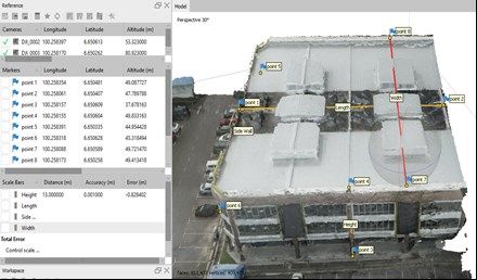
The 1st International Conference on Engineering and Technology (ICoEngTech) 2021          IOP Publishing
Journal of Physics: Conference Series            1962 (2021) 012057 doi:10.1088/1742-6596/1962/1/012057

tool in software and the actual measurement value is compared with the measured value in software.
Subsequently, the horizontal path is suitable for mapping than vertical path using UAV as the accuracy
of 3D measurement is accurate with smaller error value. For future work, this project can be applied for
mapping road design, terrain and slope.

Acknowledgments
The authors would also like to thank the Faculty of Electrical Engineering Technology is well-known
for providing the necessary facilities for this work

Reference
[1] Latha, T. P., NagaSundari, K., & Prasad, M. V. V. S. V. (2019). Remote Sensing Uav/drone
Technology as a Tool for Urban Development Measures in Apcrda. International Archives of the
Photogrammetry, Remote Sensing and Spatial Information Sciences, 42(2/W13).
[2] Śledź, S., Ewertowski, M., & Piekarczyk, J. (2021). Applications of unmanned aerial vehicle (UAV)
surveys and Structure from Motion photogrammetry in glacial and periglacial
geomorphology. Geomorphology, 107620.
[3] Jang, G., Kim, J., Yu, J. K., Kim, H. J., Kim, Y., Kim, D. W., ... & Chung, Y. S. (2020). Cost-
Effective Unmanned Aerial Vehicle (UAV) Platform for Field Plant Breeding Application. Remote
Sensing, 12(6), 998.
[4] Adamopoulos, E., & Rinaudo, F. (2020). UAS-based archaeological remote sensing: Review, meta-
analysis and state-of-the-art. Drones, 4(3), 46.
[5] Arif, M., Alghamdi, K. K., & Sahel, S. A. (2021). Role of Ma-chine Learning Algorithms in Forest
Fire Management: A Litera-ture Review. J Robotics Autom, 5(1), 212-226.
[6] DARWIN, N. B. (2017). Unmanned Aerial Vehicle Large Scale Mapping For Coastal Erosion
Assessment (Doctoral dissertation, Universiti Teknologi Malaysia).
[7] Adade, R., Aibinu, A. M., Ekumah, B., & Asaana, J. (2021). Unmanned Aerial Vehicle (UAV)
applications in coastal zone management—a review. Environmental Monitoring and
Assessment, 193(3), 1-12.
[8] Kaamin, M., Fadzil, M. A. F. M., Razi, M. A. M., Daud, M. E., Abdullah, N. H., Nor, A. H. M., &
Ahmad, N. F. A. (2020, April). The Shoreline Bathymetry Assessment Using Unmanned Aerial Vehicle
(UAV) Photogrammetry. In Journal of Physics: Conference Series (Vol. 1529, No. 3, p. 032109). IOP
Publishing.
[9] Hamylton, S. M., Morris, R. H., Carvalho, R. C., Roder, N., Barlow, P., Mills, K., & Wang, L.
(2020). Evaluating techniques for mapping island vegetation from unmanned aerial vehicle (UAV)
images: Pixel classification, visual interpretation and machine learning approaches. International
Journal of Applied Earth Observation and Geoinformation, 89, 102085.
[10] Chen, K., Reichard, G., Akanmu, A., & Xu, X. (2021). Geo-registering UAV-captured close-range
images to GIS-based spatial model for building façade inspections. Automation in Construction, 122,
103503.
[11] Nex, F., Duarte, D., Steenbeek, A., & Kerle, N. (2019). Towards real-time building damage
mapping with low-cost UAV solutions. Remote sensing, 11(3), 287.
[12] Hoffer, N. V., Coopmans, C., Jensen, A. M., & Chen, Y. (2014). A survey and categorization of
small low-cost unmanned aerial vehicle system identification. Journal of Intelligent & Robotic
Systems, 74(1), 129-145.
[13] Fujii, Y., Fodde, E., Watanabe, K., & Murakami, K. (2009). Digital photogrammetry for the
documentation of structural damage in earthen archaeological sites: The case of Ajina Tepa,
Tajikistan. Engineering Geology, 105(1-2), 124-133.
[14] Zongjian, L. I. N. (2008). UAV for mapping—low altitude photogrammetric survey. International
Archives of Photogrammetry and Remote Sensing, Beijing, China, 37, 1183-1186.
[15] W. A. Mustafa and M. M. M. A. Kader. (2018). Binarization of Document Image Using Optimum
Threshold Modification. J. Phys. Conf. Ser., 1019 (012022), pp. 1–8.

                                                    6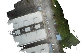
You can also read