Wild Springs Solar Project - DOE/EA-2068 - Draft Environmental Assessment Pennington County, South Dakota - Department of Energy
←
→
Page content transcription
If your browser does not render page correctly, please read the page content below
Wild Springs Solar Project
  Draft Environmental Assessment
  Pennington County, South Dakota

           DOE/EA-2068
            April 2021
Table of Contents
Introduction and Background ................................................................................... 1
Purpose and Need for WAPA’s Federal Action ...................................................................... 1
Wild Springs Solar’s Purpose and Need .................................................................................. 1
Proposed Action and Alternatives ............................................................................ 2
No Action Alternative.............................................................................................................. 2
Alternatives Considered but Eliminated from Further Study .................................................. 2
Proposed Action....................................................................................................................... 2
Solar Panels and Racking ................................................................................................3
Electrical Collection System ...........................................................................................4
Inverter/Transformer Skids .............................................................................................4
Access Roads ..................................................................................................................5
Fencing & Cameras .........................................................................................................5
Laydown Areas ...............................................................................................................5
Collector Substation ........................................................................................................5
Operation and Maintenance Building .............................................................................6
Weather Stations .............................................................................................................6
Parking ............................................................................................................................6
Stormwater Drainage Basins ...........................................................................................6
Transmission Line ...........................................................................................................6
Construction Activities ...................................................................................................7
Operation .........................................................................................................................8
Decommissioning and Reclamation................................................................................9
Affected Environment and Environmental Consequences ..................................... 11
Geology and Soils .................................................................................................................. 11
Environmental Impacts: Proposed Action ...................................................................13
Environmental Impacts: No Action Alternative ..........................................................14
Air Quality and Emissions ..................................................................................................... 14
Environmental Impacts: Proposed Action ...................................................................14
Environmental Impacts: No Action Alternative ..........................................................14
Land Use and Land Cover ..................................................................................................... 15
Environmental Impacts: Proposed Action ...................................................................16
Environmental Impacts: No Action Alternative ..........................................................19
Water Resources .................................................................................................................... 19
Environmental Impacts: Proposed Action ...................................................................20
Environmental Impacts: No Action Alternative ..........................................................21
Federally Listed Threatened and Endangered Species .......................................................... 21
Environmental Impacts: Proposed Action ...................................................................23
Environmental Impacts: No Action Alternative ..........................................................24
Fish and Wildlife ................................................................................................................... 24
Environmental Impacts: Proposed Action ...................................................................30
Environmental Impacts: No Action Alternative ..........................................................36
Page iCultural Resources ................................................................................................................. 36
Environmental Impacts: Proposed Action ...................................................................39
Environmental Impacts: No Action Alternative ..........................................................40
Socioeconomic Conditions and Environmental Justice ......................................................... 40
Environmental Impacts: Proposed Action ...................................................................41
Environmental Impacts: No Action Alternative ..........................................................43
Visual Resources ................................................................................................................... 43
Environmental Impacts: Proposed Action ...................................................................43
Environmental Impacts: No Action Alternative ..........................................................44
Roads and Traffic .................................................................................................................. 44
Environmental Impacts: Proposed Action ...................................................................44
Environmental Impacts: No Action Alternative ..........................................................45
Greenhouse Gases and Climate Change ................................................................................ 45
Cumulative Impacts ............................................................................................................... 46
Public Involvement and Coordination .................................................................... 47
Public Involvement ................................................................................................................ 47
Tribal Consultation ................................................................................................................ 48
References ............................................................................................................... 50
Page iiList of Tables
Table 1: Estimated Project Facility Acreages within the Project Footprint .................... 3
Table 2 Soil Characteristics within the Project Boundary ........................................... 12
Table 3 Summary of Land Cover in the Project Boundary .......................................... 15
Table 4 Summary of Land Cover Impacts Within the Project Footprint ..................... 17
Table 5 Summary of Wildlife Studies for the Wild Springs Solar Project ................... 24
Table 6 Summary of Grassland Bird Species Observed during Breeding Bird Surveys
....................................................................................................................... 27
Table 7 Previously Recorded Archaeological Sites and Historic Architectural Resources
within One-half Mile of the Project Boundary ............................................... 37
Table 8 Existing Socioeconomic Environmental in the Project Vicinity ..................... 40
Table 9 List of Preparers and Technical Support, Management, and Reviewers ......... 47
Table 10 Summary of Public Scoping Comments ......................................................... 47
List of Figures
Figure 1 – Project Location
Figure 2 – Project Boundary Refinement
Figures 3 – Preliminary Project Layout
Figure 4a-d – Detailed Preliminary Project Layout
Figure 5 – Land Use
Figure 6 – Waterbodies, Wetlands, and Floodplains
List of Appendices
Appendix A – Natural Resource Strategy
Appendix B – Vegetation Management Plan
Appendix C –Visual Renderings
Appendix D – Public Involvement
Page iiiAcronym List
Acronym Definition
AC alternating current
Basin Electric Basin Electric Power Cooperative
BCC Birds of Conservation Concern
BMP best management practice
CEQ Council on Environmental Quality
DC direct current
EA Environmental Assessment
EPA U.S. Environmental Protection Agency
FEMA Federal Emergency Management Agency
kV kilovolt
MW megawatt
NEPA National Environmental Policy Act
NHD National Hydrography Dataset
NLCD National Land Cover Database
NLEB northern long-eared bat
NRCS Natural Resources Conservation Service
O&M building operations and maintenance building
Project Wild Springs Solar Project
Project Boundary Approximately 1,499-acre area of privately-owned land for which
Wild Springs Solar, LLC has leases and purchase options to allow
siting and construction of the Project.
Project Footprint Approximate 1,108-acre area where Wild Springs Solar, LLC
proposes to build the Wild Springs Solar Project facilities
PV photovoltaic
SCADA Supervisory Control and Data Acquisition
SDDENR South Dakota Department of Environment and Natural Resources
SDDOT South Dakota Department of Transportation
SDGFP South Dakota Department of Game, Fish, and Parks
SGCN South Dakota Department of Game, Fish, and Parks Species of
Greatest Conservation Need
SHFC U.S. Fish and Wildlife Service Species of Habitat Fragmentation
Concern
SHPO State Historic Preservation Office
SPP Southwest Power Pool
SWPPP Stormwater Pollution Prevention Plan
THPO Tribal Historic Preservation Officer
UDP Unanticipated Discovery Plan
Page ivAcronym Definition
USDA U.S. Department of Agriculture
USFWS U.S. Fish and Wildlife Service
USGS U.S. Geological Survey
VMP Vegetation Management Plan
WAPA Western Area Power Administration
Wild Springs Solar Wild Springs Solar, LLC
WNS White-Nose Syndrome
Page vChapter 1 Introduction and Background
Introduction and Background
The Western Area Power Administration (WAPA) is one of four power marking administrations
within the U.S. Department of Energy. WAPA’s mission is to market and deliver clean,
renewable, reliable, cost-based federal hydroelectric power and related services. WAPA’s vision
is to continue to provide premier power marketing and transmission services to WAPA
customers, as well as contribute to enhancing America’s energy security and sustaining the
nation’s economic vitality. WAPA’s customers include Federal and state agencies, cities and
towns, rural electric cooperatives, public utility districts, irrigation districts and Native American
tribes. They, in turn, provide retail electric service to millions of consumers in the West.
Transmission capacity in excess of the amount WAPA requires for the delivery of long-term firm
capacity and energy to current contractual electrical service customers of the Federal
Government is offered in accordance with its Open Access Transmission Service Tariff (Tariff).
Since October 2015 WAPA’s Upper Great Plains Region (WAPA-UGP) has been a transmission
owner member of Southwest Power Pool (SPP), having placed its qualifying facilities under the
functional control of SPP. The provision of excess transmission capacity on and interconnection
to WAPA-UGP’s facilities is in accordance with the SPP Tariff.
Wild Springs Solar, LLC (Wild Springs Solar) proposes to construct and operate the Wild
Springs Solar Project (Project) on 1,499 acres of privately-owned land in Pennington County,
South Dakota (Project Boundary), approximately one-half mile south of New Underwood, South
Dakota (Figure 1 – Project Location). In May 2017, Wild Springs Solar submitted an
interconnection request to SPP to connect the Project to WAPA-UGP’s transmission system at
its New Underwood Substation. WAPA’s decision to grant or deny the interconnection request
is considered a federal action under the National Environmental Policy Act (NEPA). Therefore,
this Environmental Assessment (EA) was prepared to analyze the impacts of the Project.
Purpose and Need for WAPA’s Federal Action
WAPA must consider and respond to Wild Spring Solar’s interconnection request in accordance
with the SPP Tariff and the Federal Power Act.
Wild Springs Solar’s Purpose and Need
The purpose of the Project is to generate and distribute solar photovoltaic (PV) energy to meet
future demands, as projected in Basin Electric Power Cooperative’s (Basin Electric’s) 2018
annual report. Wild Springs has entered into a Power Purchase Agreement with Basin Electric,
who is taking the entire output of the Project for 15 years, starting in 2022.
1Chapter 2 Proposed Action and Alternatives
Proposed Action and Alternatives
This chapter describes the respective actions WAPA and Wild Springs Solar propose to take (the
Proposed Action), as well as practical alternatives to the actions.
No Action Alternative
Under the No Action Alternative, WAPA would not enter into an interconnection agreement
with Wild Springs Solar and would not allow the Project to interconnect to WAPA’s
transmission system. Although the Project could pursue an interconnection with a private utility,
for comparison purposes, this alternative assumes the Project would not be built. Current
conditions would likely continue, including farming (cultivated crops), and livestock grazing,
which is the primary land use in the Project Boundary.
Alternatives Considered but Eliminated from Further Study
Wild Springs Solar considered several project sites based on four key factors: (1) landowner
interest; (2) securing contiguous parcels; (2) proximity to the New Underwood Substation (i.e.,
adjacency); and (4) sufficient development area to allow construction and operation of a 128
megawatt (MW) solar facility. Further, as a result of site-specific studies, the Project site was
adjusted to avoid or minimize impacts to certain environmental features. Figure 2 (Project
Boundary Refinement) displays the chronology of the Project Boundary adjustments.
Proposed Action
The Proposed Action is for Wild Springs Solar to:
1. Construct and operate the Project,
2. Enter into a generator interconnection agreement with WAPA and SPP to connect the Project
to WAPA’s existing New Underwood Substation. WAPA would make any necessary design
or equipment changes to WAPA-owned facilities, as specified in the Interconnection
Agreement, to accommodate the interconnection.
Wild Springs Solar would construct, operate, and maintain the 128 MW Project, which would
include the following components:
• Solar panels and racking,
• Electrical collection system
• Inverter/Transformer skids,
• Access roads,
• Security fencing and cameras,
• Laydown areas,
• Collector substation,
2Chapter 2 Proposed Action and Alternatives
• Operations and maintenance building (O&M building),
• Up to three weather stations (up to 20 feet tall),
• Parking,
• Stormwater drainage basins, and
• Less than 1 mile of new overhead 115-kilovolt (kV) transmission line.
In total, the footprint of the facilities described above is expected to total roughly 1,100 acres. A
detailed breakdown of each facility and its anticipated footprint is shown in Table 1. The
preliminary Project design is displayed on Figures 3 and 4a-d (Preliminary Project Layout and
Detailed Preliminary Project Layout, respectively). Shifts in Project facilities may be necessary
as a result of geotechnical evaluations, landowner input, or to avoid newly identified
environmental resources. If shifts become necessary, Wild Springs and WAPA would coordinate
to determine whether additional analysis is necessary.
Table 1: Estimated Project Facility Acreages within the Project Footprint
1
Project Facilities Acres
Solar Arrays (fenced area) 1037.5
Access Roads 40.0
Laydown Areas (to be restored) 13.2
Collection lines outside the fence 9.6
Laydown Area (to be converted to parking lot) 5.7
Inverters 0.9
Stormwater Basin 0.6
Collector Substation 0.5
O&M Building 0.1
Project Total 1108.1
1
Weather Stations occupy a footprint of approximately 10 square feet. The footprint for up to three weather
stations is < 0.1 acre and is therefore not included in this table.
Solar Panels and Racking
The Project would utilize PV panels with tempered glass varying in size between approximately
4 to 7 feet long by 2 to 4 feet wide, and 1 to 2 inches thick. The panels would be installed on a
tracking rack system made of galvanized steel and aluminum with a motor that allows the panels
to rotate their angle. The panels and tracking rack system are generally aligned in rows north
and south with the PV panels facing east toward the rising sun in the morning, parallel to the
ground during mid-day, and then west toward the setting sun in the afternoon. The rotating rack
system allows the PV panels to track the solar resource throughout the day.
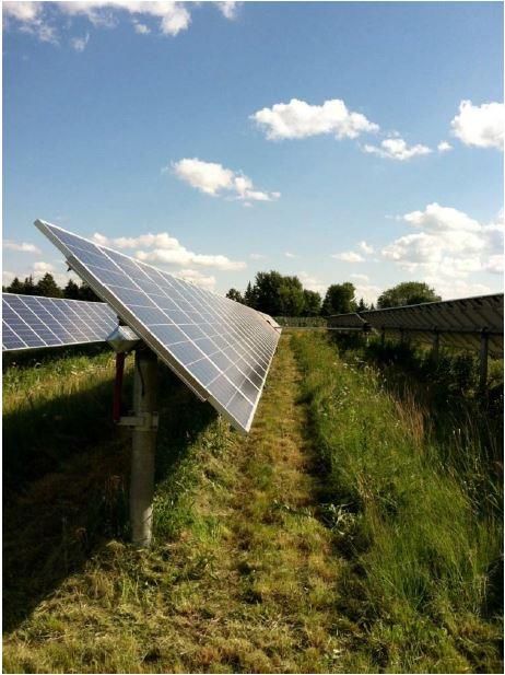
Each tracking rack would contain multiple panels. On the tracking rack system, panels would be
up to 20 feet in height from the ground to the top of the panels when at a 45-degree angle.
Ground clearance to the bottom of the panels when at a 45-degree angle is approximately 32
inches depending on topography and vegetation constraints. Image 1 below shows solar panels
oriented at a 45-degree angle.
3Chapter 2 Proposed Action and Alternatives
The tracking rack system is mounted on top of steel piers that are typically driven into the
ground, without a need for excavation or concrete to install the piers. Piers are typically installed
at eight to fifteen feet below the surface, pending site-specific conditions that would be
determined through geotechnical borings prior to construction.
Image 1 Tracking Rack System and Solar Panels at 45-Degree Angle
Electrical Collection System
The electrical collection system contains two components: direct current (DC) connecting the
panels to the inverter/transformer and alternating current (AC) connecting the
inverter/transformer to the collector substation. The electrical collection system would be
installed below-ground or a hybrid of below-ground and above-ground. In the below-ground
electrical collection system, both the DC and AC electrical lines would be buried. In the hybrid
electrical collection system, the DC electrical lines would be above-ground, strung under the
panels and the AC collection lines would be buried. All below-ground collection lines would be
installed in trenches or ploughed into place at a depth of at least four feet below grade. During all
trench excavations the topsoil and subsoil would be removed and stockpiled separately. Once the
cables are laid in the trench, the area would be backfilled with subsoil followed by topsoil.
Inverter/Transformer Skids
Regardless of the collection system configuration (below-ground or hybrid), the Project would
utilize central inverter/transformer skids at locations throughout the Project Footprint and include
a transformer to which the inverters would feed electricity. The Project’s preliminary design has
proposed 89 central inverter skids (one inverter is required for every 2-3 MW). These skids
provide the foundation for the inverter, transformer, and Supervisory Control and Data
Acquisition (SCADA) system. The skids would be placed atop a concrete slab or pier
4Chapter 2 Proposed Action and Alternatives
foundations and typically measure 10 feet wide by 25 feet long, with a structure height of
approximately 12 feet above grade. Concrete foundations would be poured onsite or precast and
assembled off-site.
The inverters would be located within the interior of the Project along access roads.
Access Roads
The Project would construct up to 20 miles of new graveled access roads that lead to the Project
facilities. These roads would be up to 16 feet wide along straight portions of the roads and wider
along curves at internal road intersections (approximately 45 feet). There are ten access points to
the Project from existing county roads. These entrances would have locked gates.
During construction, the access road area will be graded, compacted, and 4-12 inches of gravel
would be added.
Fencing & Cameras
Permanent security fencing would be installed along the perimeter of the Project Footprint.
Permanent fencing is designed to enclose eight blocks of panels, not surround the entire Project
Footprint with a single fence. Additionally, the collector substation would have its own perimeter
fencing. In both cases, the fencing would consist of a chain link fence and would extend
approximately 6 feet above grade with additional one foot of barbed wire to comply with the
National Electric Code, and to provide security and safety. Additional prairie dog exclusionary
fencing options may be utilized in portions of the Project such as chicken-wire below the chain
link fence extending below grade.
The Project would also have security cameras. Wild Springs Solar would have security lighting
at the entrances that would be down lit. The typical pole height would be ten feet and lights
would be manual by switch as well as motion activated if an intrusion is detected. There would
be lights at each inverter that would be down lit and switch controlled for repair purposes.
Laydown Areas
Wild Springs Solar would utilize ten temporary laydown areas within the Project Footprint,
totaling 15.9 acres. These areas would serve both as a parking area for construction personnel
and staging areas for Project components during construction. After construction, nine of the
laydown areas would be reseeded as described in the Land Use and Land Cover section; the
laydown area adjacent to the collector substation and O&M building would become the parking
lot (see Figures 4a-d).
Collector Substation
The collector substation would be a 34.5/115 kV step-up substation with metering and switching
gear required to connect to the transmission grid. The area within the substation would be
graveled to minimize vegetation growth in the area and reduce fire risk. The substation’s area
would be approximately 150 feet by 150 feet.
5Chapter 2 Proposed Action and Alternatives
The collector substation would contain a single, industry-standard main power transformer,
which would require a Spill Prevention, Control, and Countermeasures Plan. Other onsite
storage at the O&M building may include hydraulic oil stored in a plastic or poly tote or 55-
gallon drums on secondary containment pallets and potentially a fuel tank, for maintenance
vehicles, that would be a double walled tank with additional secondary containment.
One of two methods would be used to install substation foundations. Option 1 would be to use a
small rubber tire backhoe to dig out major foundations prior to pouring the concrete slabs.
Option 2 would use an auger/drill type machine for minor foundations.
Operation and Maintenance Building
An O&M building would be located adjacent to the collector substation. The Project would
obtain a building permit for the O&M building from Pennington County in the 3rd quarter of
2021, prior to construction. The O&M building would measure approximately 60 feet long by 40
feet wide and would be made of metal (similar to a pole barn). It would contain an office for the
onsite Plant Manager, a technician room, restroom, and storage area for equipment to operate
and maintain the Project. Equipment includes a SCADA cabinet, spare panels, spare parts for the
substation and equipment to operate the substation, as well as safety equipment for working with
live electricity.
Weather Stations
The Project would include up to three weather stations up to 20 feet in height. The weather
stations would be within the Project Boundary; the final locations would be determined
following final engineering in the 3rd quarter of 2021.
Parking
A parking lot would be located adjacent to the O&M building and would be approximately 500
square feet with the final size being determined in accordance with the Pennington County
Zoning Ordinance in the 3rd quarter of 2021. The parking lot would be gravel or paved.
Stormwater Drainage Basins
Stormwater drainage basins may be needed as stormwater runoff mitigation according to the
Pennington County Stormwater Quality Manual. While the vegetation that would be planted
between the arrays would likely be sufficient to meet the stormwater best management practice
(BMP) requirements, Wild Springs Solar has preliminarily designed one drainage basin in the
southwest portion of the Project Footprint that covers 0.6-acre (see Figures 3 and 4a-d). No
facilities would be placed in the drainage basin, which is located in an existing low area. This
area would be vegetated with a wet seed mix that would help stabilize soils after rain events.
Transmission Line
The exact transmission line routing to interconnect the Project into the substation has not yet
been determined; however, it would be located within a corridor of the Project’s leased lands
until it crosses into the New Underwood Substation parcel. Additionally, the gen-tie transmission
6Chapter 2 Proposed Action and Alternatives
line will be routed such that it does not cross existing transmission lines. The gen-tie routing area
is displayed on Figure 3.
Construction Activities
Construction of the Project would take as many as twelve months beginning as early as fall of
2021 and would be completed by the end of 2022. The construction workforce required to
complete the Project would be over 150 workers at peak construction.
During construction, equipment and work vehicles would travel to and from the site. Typical
construction equipment such as scrapers, dozers, dump trucks, watering trucks, motor graders,
vibratory compactors and pile drivers, pickup trucks, and backhoes would be used during
construction. Specialty construction equipment that may be used during construction would
include:
• skid steer loader;
• medium duty crane;
• all-terrain forklift;
• concrete truck and boom truck;
• high reach bucket truck; and
• truck-mounted auger or drill rig.
An overview of construction activities follows.
Geotechnical
Geotechnical and pull testing studies would be performed to determine the topsoil and subsoil
types, and the mechanical properties of the soils. These variables would be used to engineer the
solar array foundation system.
Site Clearing & Vegetation Removal
Depending on timing of the start of construction, residual row-crop debris from the 2021 harvest
season may need to be cleared. Alternatively, and depending on construction timing, Wild
Springs Solar may plant a cover crop in Spring 2021 that is compatible with the Project’s
Vegetation Management Plan (VMP). This cover crop would stabilize soils if row crops are not
planted that year.
Earthwork
During grading, topsoil and organic matter would be stripped and segregated from the subsoil
(depending on the depth of grading cut). Some grading would be required to provide a more
level workspace and maintain soil stability in areas with a slope greater than five percent
(approximately 25 percent of the Project Boundary, however the areas that would be graded
would be less as grading activities would be limited to the final development area). Topsoil shall
have temporary and permanent erosion control and soil stabilization measures established in
accordance with the Project’s Stormwater Pollution Prevention Plan (SWPPP). The earthwork
7Chapter 2 Proposed Action and Alternatives
activities would be completed using typical civil construction equipment – scrapers, bulldozers,
front-end loaders, backhoes, or skid-steers.
Restoration
Following construction, areas that would not contain permanent facilities (area under the arrays
and the laydown yards that would not be converted into permanent parking for operations) would
be stabilized with sediment stabilization and erosion control measures such as silt fence and
biologs and re-vegetated according to the VMP. The site would be seeded with site specific seed
mixes developed in coordination with the South Dakota U.S. Department of Agriculture (USDA)
Natural Resources Conservation Service (NRCS) and includes seed mixes specific to clay and
loam soils and plant species that are adapted to the semi-arid climate.
The VMP outlines two vegetation maintenance strategies that may be implemented at the
Project: mowing and grazing. Mowing would take the form of traditional mowing once
vegetation reaches a height of 18-24 inches during the growing season. Alternatively, Wild
Springs Solar may decide to use grazing with sheep as a long-term vegetation management
technique.
Operation
The Project would be professionally maintained and operated by Wild Springs Solar, an affiliate,
or contractor. Primary tasks include scheduled annual inspection(s) of electrical equipment and
vegetation management, as well as snow removal on access drives.
The expected service life of the Project is 20 to 30 years, and Wild Springs Solar estimates that
the Project would result in up to four full-time permanent positions to operate and maintain the
Project facilities. A maintenance plan would be created for the Project to ensure the performance
of the solar facilities. The frequency of maintenance inspections varies by task and range from
annually to monthly.
Once construction is complete, the solar facility would see one to two trucks on site daily.
Supervisory Control and Data Acquisition System
The solar arrays would communicate directly with the SCADA system for remote performance
monitoring, energy reporting and troubleshooting. The SCADA system provides data on solar
generation and production, availability, meteorology, and communications. The SCADA system
allows monitoring of, and communications with, the Project and relays alarms and
communication errors. All the monitored data would be managed by Wild Springs Solar on-site
in addition to a qualified subcontractor that would remotely monitor the site 24 hours a day, 7
days a week through the SCADA system.
Facility Maintenance
Housekeeping of the Project facilities would include road maintenance, vegetation maintenance
(method is to be determined; either traditional mowing or sheep and/or lamb grazers would be
utilized), fence and gate inspection, lighting system checks, and PV panel washing (if required;
8Chapter 2 Proposed Action and Alternatives
minimal to no washing is anticipated to be needed at Project facilities due to the naturally
occurring precipitation). Panel manufactures do not require washing panels for regular product
maintenance. Given the amount of historical rainfall in the area, Wild Springs does not anticipate
panels will need to be washed as only a tenth of an inch of precipitation is necessary to remove
any soiling on the panels (such as dust or bird droppings). In the unlikely scenario that panels
would need to be washed, water will be brought in by truck from a municipal water source in
New Underwood, Box Elder, or Rapid City, and a pressure washer would be used.
Approximately 20 gallons of water per megawatt hour would be required for panel washing. For
comparison, a typical family uses approximately 20,000 gallons each year, which is more than
the amount of water needed per MW of solar generation capacity (Solar Energy Industries
Association, 2021). No chemicals would be used that would create waste or require the
collection or disposal of the water. Lastly, any panels washing would occur in targeted and
specific areas; the whole Project Footprint would not need panel washing.
Decommissioning and Reclamation
At the end of the Project’s useful life, Wild Springs Solar would either take necessary steps to
continue operation of the Project (such as re-permitting and retrofitting) or would decommission
the Project and remove facilities. In accordance with Section 317-A-15 of the Pennington County
Zoning Ordinance (July 10, 2019), decommissioning activities would include:
• Dismantling and removing all Project-related equipment, foundations, and ancillary
equipment to a depth of forty-two (42) inches below grade. Any soil disturbance
associated with decommissioning would include topsoil segregation.
• Removing the operation and maintenance facility and access roads, unless the landowners
request in writing that all or any portion of the facility and/or access roads remain in
place. Access road restoration would include removal of surface road material and
restoration of the roads to substantially the same physical condition that existed
immediately before construction of the Project.
• Restoration of the Project site, including: decompaction; revegetation (in accordance with
NRCS guidance or landowner request); and to the extent possible, reclamation to the
approximate original topography and original or better topsoil quality that existed
immediately prior to construction of the Project.
• Executing haul road agreements, as needed addressing the Project’s use, improvement,
and post-decommissioning restoration and repair of existing, maintained roads, including
any associated road restoration and repair costs.
• Standard decommissioning practices would be utilized, including dismantling and
repurposing, salvaging/recycling, or disposing of the solar energy improvements.
• In accordance with County and State requirements, Wild Springs Solar would provide a
financial assurance instrument to cover the costs of decommissioning.
Removal and Disposal of Project Components
The removal and disposal details of the Project components are found below:
• Panels: Panels inspected for physical damage, tested for functionality, and removed from
racking. Functioning panels packed and stored for reuse (functioning panels may produce
9Chapter 2 Proposed Action and Alternatives
power for another 25 years or more). Non-functioning panels packaged and sent to the
manufacturer or a third party for recycling or another appropriate disposal method.
• Racking: Racking uninstalled, sorted, and sent to metal recycling facility.
• Steel Pier Foundations: Steel piles removed and sent to a recycling facility.
• Wire: belowground wire abandoned in place at depths greater than four feet. Wire above
four feet removed and packaged for recycling or disposal.
• Conduit: Above-ground conduit disassembled onsite and sent to recycling facility.
• Junction boxes, combiner boxes, external disconnect boxes, etc.: Sent to electronics
recycler.
• Inverter/Transformer: Evaluate remaining operation life and resell or send to
manufacturer and/or electronics recycler.
• Concrete pad(s): Sent to concrete recycler.
• Fence: Fence would be sent to metal recycling facility and wooden posts for the
agricultural fence would be properly disposed.
• Computers, monitors, hard drives, and other components: Sent to electronics recycler.
Functioning parts can be reused.
Recycling of solar panels and equipment is rapidly evolving and can be handled through a
combination of sources such as some manufactures, PVCycle (an international program that
some of the silicon manufactures participate in) or waste management companies.
Restoration/Reclamation of Facility Site
After all equipment is removed, the facility the site would be restored to agricultural production
that existed prior to construction of the solar facilities. Holes created by steel pier foundations
and fence poles, concrete pads, reclaimed access road corridors and other equipment would be
filled in with subsoil, the site would be reclaimed approximately to the original topography that
existed immediately prior to construction of the Project, topsoil (original or better quality) would
be replaced, and the site would be seeded.
10Chapter 3 Affected Environment and Environmental Consequences
Affected Environment and Environmental Consequences
This chapter describes the existing environment and the expected environmental consequences of
the Proposed Action and the No Action Alternative. The affected environment for each resource
is characterized based on a review of existing data, and for some resources the results of field
investigations are included.
Geology and Soils
Based on South Dakota Department of Environment and Natural Resources (SDDENR) water
rights well completion reports, it appears that bedrock is typically encountered anywhere from
three to sixteen feet below ground (SDDENR, Undated).
There are nine unique soils within the Project Boundary; Table 2 lists the four most prevalent
soil types within the Project Boundary and presents the total acres of each of these soil types.
The majority of soils within the Project Boundary range from clay to clay loam and are not
susceptible to erosion by wind or water. The exception is Pierre clay, which is susceptible to
erosion by water when found on slopes of greater than 6 percent; within the Project Boundary,
there are 14.5 acres of this soil type on slopes greater than 6 percent.
11Chapter 3 Affected Environment and Environmental Consequences
Table 2 Soil Series Characteristics within the Project Boundary
Soil Wind Erosion Water Erosion Farmland Acres in Project Percent of Project
Series Landscape Location Texture Rating Rating Classification 1 Boundary Boundary
Kyle Nearly level to strongly Clay Not highly wind Not highly Not prime farmland 735.7 49.1
clay sloping on uplands and erodible water erodible
colluvial fans; 0 to 6%
slopes
Pierre Hillslopes on uplands; 2 Silty clay Not highly wind Highly water Not prime farmland 250.2 16.6
to 20% slope to clay erodible erodible (when
slope is > 6%) 1
Nunn Terraces or alluvial fans, Clay Not highly wind Not highly Prime Farmland if 195.4 13.0
or in drainageways; 0 to loam erodible water erodible Irrigated
6% slopes
Hisle Nearly level to Silt loam Not highly wind Not highly Not prime farmland 182.0 12.1
moderately sloping on erodible water erodible
uplands; 0 to 6% slopes
1
Of the 250.2 acres of Pierre clay within the Project Boundary, only 14.5 acres are found on slopes of greater than 6 percent.
Source: Soil Survey Staff, Natural Resources Conservation Service, U.S. Department of Agriculture, 2020
12Chapter 3 Affected Environment and Environmental Consequences
Environmental Impacts: Proposed Action
The average depth to bedrock within the vicinity of the Project ranges from three to sixteen feet;
some Project infrastructure may be installed at eight to fifteen feet below the surface. These
components include:
1. If the under-ground collection system is used and shallow bedrock is encountered, there may
be some areas where collection lines would be buried less than four feet from the ground
surface to avoid impacting bedrock.
2. If the steel piers for the tracking rack system encounter bedrock, engineering solutions such
as helical screws would be used to avoid blasting. Installation of the steel piers with helical
screws to the bedrock is not expected to affect the structure integrity of the bedrock.
About 234 acres of soils would be temporarily impacted during construction. Of these 234 acres
of soils, about 84 acres are classified as prime farmland, if irrigated, and about 7 acres are Pierre
clay with greater than 6 percent slopes (Pierre clay soils are susceptible to erosion by water when
found on slopes of greater than 6 percent, as noted above). Soils would be disturbed via activities
like grading, trenching, and vegetation removal. These types of activities can lead to increased
runoff, compaction, and mixing of soil layers. In the remaining 874 acres within the Project
Footprint, no soil disturbance would occur during construction and existing vegetation would be
left in place to maintain soil stability. The Project would not impact prime farmland.
Nearly 48 acres of soils would be permanently impacted by Project operation and long-term
infrastructure, for example, the O&M building, collector substation, parking areas, and roads.
These new solid-surface features would reduce the ability of soils to infiltrate precipitation to
groundwater, potentially increasing the volume and rates of stormwater runoff.
To minimize impacts on geology and soils, the following BMPs would be used:
• Utilize the existing landscape (e.g., slope, drainage, use of existing roads), and avoid
placing solar arrays within low-lying drainages, to minimize or avoid grading work and
land disturbance.
• Develop and implement a SWPPP for the Project.
• Use appropriate silt fences, mulching, and temporary seeding to minimize soil exposure
and to prevent eroded soil from leaving the disturbed area.
• Strip topsoil and organic matter, keeping topsoils segregated from subsoil. Temporary
and permanent stabilization measures would be installed in areas of stripped topsoil, in
accordance with the Project’s SWPPP. Topsoil and subsoil would be replaced in the order
they were removed, and the grade would be blended with existing topography, after
grading is complete.
• Work during dry conditions, whenever possible, to minimize rutting, erosion, and runoff.
• Disturbed areas would be regraded to approximate original contours and revegetated with
a native plant community in order to establish stable ground cover successfully, reduce
erosion, reduce runoff, and improve infiltration.
13Chapter 3 Affected Environment and Environmental Consequences
Environmental Impacts: No Action Alternative
Under the No Action Alternative, no new impact on soil or geology resources would occur.
Existing impacts to soils, such as incremental compaction and erosion due to grazing, and due to
farming are likely to continue.
Air Quality and Emissions
The nearest air quality monitoring station is in Rapid City, Pennington County, approximately 11
miles west of the Project Boundary (SDDENR, 2016). In general, air quality in Pennington
County is good and all of South Dakota is in attainment with national air quality standards (EPA,
2020). The primary emission sources that exist within the Project Boundary include agriculture
and farming equipment and vehicle use along Interstate 90.
Environmental Impacts: Proposed Action
Construction activities could release air emissions of criteria pollutants, volatile organic
compounds, greenhouse gas emissions (e.g., carbon dioxide), and small amounts of hazardous air
pollutants. Air emissions would include:
• increase in fugitive dust emissions due to truck and equipment traffic.
• emissions from diesel trucks and construction equipment.
The Wild Springs Solar construction team will monitor dust from construction traffic. Standard
industry practices would be implemented to control dust including mulching exposed soils,
wetting exposed soils, maintaining vegetative cover (both cover crops and permanent
vegetation), and reduced speed limits. Emissions from construction vehicles would be minimized
by keeping construction equipment in good working order. As described above in the Geology
and Soils Section (Table 2), the soils in the Project Boundary are not highly wind erodible, so
wind erosion of soils is not anticipated.
Long term, negligible amounts of dust, vehicle exhaust emissions, and combustion-related
emissions from diesel emergency generators would occur during maintenance activities.
Operation of the collector Substation would produce minute amounts of ozone and nitrogen
oxides emissions as a result of atmospheric interactions with the energized conductors and the
use of sulfur hexafluoride-filled circuit breakers. Sulfur hexafluoride is a greenhouse gas, and
therefore, equipment leaks could contribute to air quality impacts. Wild Springs Solar’s O&M
staff would also conduct monthly inspections of the collector substation to detect any equipment
leaks in compliance with the National Electric Code.
Environmental Impacts: No Action Alternative
No impact on air quality would occur under the No Action Alternative and current emissions
would be expected to continue at a similar rate. Presently, dust emissions occur annually during
farming activities such as haying and harvesting.
14Chapter 3 Affected Environment and Environmental Consequences
Land Use and Land Cover
Land within the Project Boundary is privately owned (except for WAPA’s substation parcel) and
predominantly used for livestock grazing and agricultural production. Cattle is the top livestock
raised in Pennington County (USDA, 2017), and both forage crops and pasture land support
cattle and other livestock operations in the area. As described further below, much of the land
cover within the Project Boundary is used for livestock grazing (i.e., pasture land). The top crops
grown in Pennington County (in acres) include forage (hay, haylage, grass silage, and
greenchop), followed by wheat (predominantly winter wheat), corn, and sunflowers.
Commercial and utility developments include several existing transmission lines that tie into the
New Underwood Substation and an existing railroad line runs along the northern boundary of the
Project Boundary. Additionally, Garrett Road, 161st Avenue, and 230th Street bisect portions of
the Project Boundary.
There are no irrigated lands major industries, or areas zoned for residential or commercial land
uses in the Project Boundary. In addition, there are no recreation lands, tribal lands, cemeteries,
places of historical significance, or other public facilities within or adjacent to the Project
Boundary.
Table 3 presents the total acres of various land cover types within the Project Boundary. Site
visits and field studies are summarized in Appendix A. The predominant land cover types are
herbaceous land and cultivated cropland (see Figure 5 – Land Use).
Table 3 Summary of Land Cover in the Project Boundary
Percent of
NLCD Category Field Observations Total Acres Total
Cultivated Crops Alfalfa, hay, and wheat (dryland) 320.7 21.4
Open Water Delineated wetland 1.3 0.1
Emergent Herbaceous Delineated wetland 0.4 < 0.1
Wetlands
Herbaceous Includes pasture, hay, and fallow grassland areas 1,130.8 75.5
Barren Land Associated with the WAPA substation – gravel 6.0 0.4
pad
Shrub/Scrub Associated with the WAPA substation – no 1.5 0.1
shrubs observed
Developed, All Categories Generally, roads bisecting the Project Boundary 37.9 2.5
Total 1,498.6 100
Source: MRLC, 2016
Dominant or co-dominant grass species observed in lands classified as Herbaceous include
western wheat grass, crested wheatgrass, blue grama, buffalograss, and Poa spp. (bluegrass). In
general, areas with less-intensive grazing and on ridgetops with shallow soils are dominated by
the native shortgrass species blue grama and buffalograss, whereas the more heavily grazed and
disturbed areas are dominated by the non-native crested wheat grass or bluegrass. Observations
made during field surveys indicate that cattle have seasonal access to graze these areas, and
much of the acreage modeled as herbaceous land appears to be seasonally hayed. However, most
15Chapter 3 Affected Environment and Environmental Consequences
areas of herbaceous land are highly fragmented by fences and existing transmission lines and
roadways, which limits the available grazing areas to noncontiguous parcels of 80 acres or less.
No rare plants were observed during field surveys.
Field verification efforts noted that dryland cultivated cropland is predominantly used to produce
annual crops such as alfalfa, hay crop, and wheat and also includes all land being actively tilled.
Cultivated cropland is predominately in the northwestern portion of the Project Boundary.
The Emergent Herbaceous Wetland NLCD category includes areas where perennial herbaceous
vegetation accounts for greater than 80 percent of vegetation cover and the soil is periodically
saturated with water. Within the Project Boundary, emergent herbaceous wetlands are associated
with Boxelder Creek. Field observations noted few wetland communities within the Project
Boundary. These few wetland communities were found within small drainage swales or around
embanked ponds and typically contain a small fringe component of sedge or cattails depending
on wetland type.
Areas categorized as developed (all types) by the NLCD data are primarily associated with roads
bisecting the Project Boundary, the developed area around the WAPA substation, and the
existing transmission lines throughout the area. In addition, the Rapid City, Pierre & Eastern
Railroad runs parallel to the northern boundary of the Project Boundary.
Vegetation in the developed and barren landcover categories generally lack diversity, consisting
largely of invasive and noxious species, or lack vegetation all together (MRLC, 2016). The
existing WAPA substation is classified as barren and shrub/scrub cover types.
The Open Water category includes embanked wetlands and stock ponds in the Project Boundary,
and generally exhibit less than 25 percent vegetative cover. As such, this category is not
discussed further in this section and instead, can be found in the Water Resources section.
Invasive plant species observed onsite include Canada thistle (located primarily along roadsides,
disturbed areas, and wetland perimeters), Russian thistle, Russian olive, cheatgrass, and Japanese
brome. Canada thistle is the only species on the State noxious weed list; however, cheatgrass, an
annual invasive grass that is native to Europe and eastern Asia, is a broad concern across all
western rangelands and contributes to increased wildfire frequency and risk, reduced soil health
(due to its shallow root systems), and less diverse native plant communities.
Environmental Impacts: Proposed Action
Table 4 provides the total impacts on existing land cover within the Project Footprint based on
the preliminary design. No open water, emergent herbaceous wetlands, or barren land is within
the Project Footprint; therefore, these NLCD categories are not included in Table 4.
16Chapter 3 Affected Environment and Environmental Consequences
Table 4 Summary of Land Cover Impacts Within the Project Footprint
NLCD Category
Developed,
Cultivated All
Crops Herbaceous Shrub/Scrub Categories Total
Project Facilities (acres) (acres) (acres) (acres) (acres)
Solar Arrays (fenced area) 280.0 755.2 0.3 1.9 1037.4
Access Roads 7.6 32.1 -- 0.3 40.0
Laydown Areas (to be restored) 0.7 12.0 -- 0.5 13.2
Collection lines outside the fence 0.2 8.5 -- 0.9 9.6
Laydown Area (to be converted to -- 5.5 -- 0.2 5.7
parking lot)
Inverters 0.2 0.7 -- -- 0.9
Stormwater Basin -- 0.6 -- -- 0.6
Collector Substation -- 0.5 -- -- 0.5
O&M Building -- 0.1 -- -- 0.1
Project Total 288.7 815.2 0.3 3.8 1,108.1
Source: MRLC, 2016
While the precise route of the gen-tie transmission line is pending, it would be located within a
corridor of the Project’s leased lands until it crosses over into the New Underwood substation
parcel (see Chapter 2). Based on review of the NLCD land cover types shown on Figure 5 (Land
Use), construction and operation of the gen-tie transmission line would impact herbaceous and
developed land cover types. These impacts would occur as a result of the 4-5 transmission pole
structures, which typically have a footprint of 5-10 foot diameter per the structure footing, for a
total of less than .01 acre for all poles (or approximately 393 square feet).
There are a total of 288.7 acres of cultivated cropland within the Project Footprint and
construction and operation of the Project would remove these lands from production for the life
of the Project (Table 4) and convert their use to developed land. Areas of cultivated cropland
within the Project Footprint would be reseeded with a native seed mix that is similar to the
surrounding herbaceous landscape for the life of the Project.
Similarly, construction of the Proposed Action would also remove 815.2 acres of herbaceous
land currently being used for grazing and convert its use to developed for the life of the Project.
While a solar facility is considered a developed land use, most of the land cover within the
Project Footprint would be herbaceous with the exception of the access roads, Project substation,
O&M building, parking lot, and inverters.
Construction of the solar facilities would not require removal of all vegetation within the Project
Footprint. Rather, ground disturbance and vegetation clearing would be limited to some areas
with greater than 5 percent slope and permanent facilities such as access roads, Project
substation, O&M building, parking lot, and inverters. These facilities would permanently convert
47.2 acres of cultivated cropland (7.8 acres), herbaceous land (38.9 acres), and developed land
(0.5 acre) to impervious surfaces for the life of the Project.
17Chapter 3 Affected Environment and Environmental Consequences
Wild Springs Solar would install fencing around the Project Footprint to prevent livestock from
entering the solar facility during construction or operation and would work with landowners on
the following issues: installation of gates and cattle guards where access roads cross existing
fence lines, access control, signing of open range areas, and traffic management (e.g., vehicle
speed management).
No lands used for recreation are present within the Project Boundary; therefore, the Proposed
Action would not affect recreational land or public use of recreational land.
After construction of the solar facility is complete, Wild Springs Solar would revegetate the
disturbed areas using a seed mix that includes recommendations provided by the NRCS and a
cover crop. Approximately 96 percent of the land in the Project Footprint would be restored as
open, herbaceous (i.e., within the racking area) rangeland cover (1,060.8 acres). Roughly 4
percent (47.3 acres) would be permanently converted to developed land with impervious surfaces
(i.e., the substation and O&M building, inverter skids, parking areas, and access roads).
Additionally, Wild Springs Solar would remove up to five isolated willow trees in the western
portion of the Project Boundary.
Wild Springs Solar developed a VMP that prescribes procedures and seed mixes that would be
used during site restoration and ongoing vegetation management during operation of the solar
facility. The VMP provides a guide to site preparation, reseeding, management of invasive
species and noxious weeds, and control of erosion/sedimentation. Post-construction restoration
work would continue for three years. Vegetation restoration targets are defined for each of the
first three years of implementation of the VMP. A copy of the VMP is provided in Appendix B.
Seed mixes were designed to be native, blend with the surrounding landscape, and were
developed in coordination with the NRCS to design a mix that would establish stable ground
cover successfully, reduce erosion, reduce runoff, and improve infiltration. Many species in the
seed mixes are similar to existing vegetation within the Project Boundary such as, blue grama
grass and Western wheatgrass.
Construction of the Project has the potential to introduce or spread noxious and invasive
species into areas where these species previously did not exist. For example, vehicles
traveling from one area to another could inadvertently spread noxious and invasive species
from roadside ditches or disturbed areas. Construction equipment will be cleaned prior to
arriving at the work site to avoid the spread of weeds when traveling within the Project
Footprint.
Additionally, the VMP outlines noxious weed and invasive plant control measures that Wild
Springs Solar would implement during operation of the Project, which includes the following:
• Identifying and treating areas of noxious weeds or invasive plants and applying herbicidal
treatments and
• Annual mowing to avoid invasive plants adding new seeds to the soil.
18You can also read