2022 OWNERS MANUAL BETAUSA.COM - Beta USA
←
→
Page content transcription
If your browser does not render page correctly, please read the page content below

2022
OWNERS MANUAL
BETAUSA.COM
XTRAINER 250 2T EUROPA - XTRAINER 300 2T EUROPA
       XTRAINER 250 2T - XTRAINER 300 2T

Thanks for you preference, and have a good time! This hand-
book contains the information you need to properly operate and
maintain your motorcycle.

The data, specifications and images shown in this manual does not constitute
an engagement on the part of BETAMOTOR S.p.A. BETAMOTOR reserves
the right to make any changes and improvements to its models at any mo-
ment and without notice.

                          Code 036.44.044.83.00

                                     1                                         EN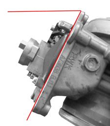
IMPORTANT

     We recommend you to check all the tightenings after the first one
     or two hours’ ride over rough ground. Special attention should
     be paid to the following parts:

     •   rear sprocket
     •   ensure that the footrests are properly fixed
     •   front/rear brake levers/calipers/discs
     •   check that the plastics are properly fastened
     •   engine bolts
     •   shock absorber bolts/swingarm
     •   wheel hubs/spokes
     •   rear frame
     •   pipe connections
     •   tensioning the chain

                                 IMPORTANT

     In the event of interventions on the vehicle, contact Betamotor
     after-sales service.

EN                                    2
CONTENTS
Operating instructions.............................................................................. 5
Symbols................................................................................................. 5
Riding safety.......................................................................................... 6
CHAPTER 1 GENERAL INFORMATION............................................. 7
Vehicle identification data........................................................................ 8
Tools kit................................................................................................. 8
Familiarizing with the vehicle................................................................... 9
Specifications....................................................................................... 10
Electrical system.................................................................................... 14
Bulbs................................................................................................... 16
Fuses................................................................................................... 16
Recommended lubricants and liquid........................................................ 16
CHAPTER 2 OPERATION.................................................................. 17
Main parts........................................................................................... 18
CONTENTS
Dashboard operating instructions............................................................ 23
Checks before and after use................................................................... 32
Running in............................................................................................ 32
Refuelling............................................................................................. 33
Oil mixer refuelling............................................................................... 34
Starting the engine................................................................................ 34
Engine shut-down.................................................................................. 34
CHAPTER 3 ADJUSTMENTS............................................................. 35
Key to symbols..................................................................................... 36
Brakes................................................................................................. 36
Clutch.................................................................................................. 37
Adjustment of gas clearance................................................................... 37
Adjusting the idle speed......................................................................... 37
Exhaust valve control adjustment............................................................. 41
Handlebar adjustment........................................................................... 41
Adjusting fork....................................................................................... 42
Shock absorber.................................................................................... 43
CHAPTER 4 CHECKS AND MAINTENANCE.................................... 45
Key to symbols..................................................................................... 46
Engine oil............................................................................................. 46
Liquid coolant....................................................................................... 47
3 ENAir filter............................................................................................... 50
Spark plug........................................................................................... 51
Carburettor.......................................................................................... 52
Front brake.......................................................................................... 54
Rear brake........................................................................................... 57
Clutch control....................................................................................... 60
Check and adjusting of steering play....................................................... 62
Front wheel.......................................................................................... 63
Fork..................................................................................................... 64
Rear suspension leverage....................................................................... 64
Tyres................................................................................................... 65
Chain.................................................................................................. 65
Headlight............................................................................................. 67
Replacing the headlight bulbs................................................................. 67
Tail light............................................................................................... 68
Battery................................................................................................. 68
CONTENTS
Fuses................................................................................................... 70
Cleaning the vehicle.............................................................................. 71
Electrical connector maintenance............................................................ 72
Prolonged inactivity............................................................................... 73
Scheduled maintenance vehicle.............................................................. 74
Tightening torque overview.................................................................... 76
CHAPTER 5 REPLACEMENTS............................................................ 77
Removal and refitting of the saddle......................................................... 78
Removing and installing air filter cover panel............................................ 79
Removing and installing the headlamp mask.......................................................... 80
CHAPTER 6 TROUBLESHOOTING................................................... 81
Troubleshooting.................................................................................... 82
CHAPTER 7 INSTRUCTIONS FOR PERIODIC INSPECTION WORKSHOPS.. 83
Instructions for periodic inspection workshops........................................... 84
EN 4OPERATING INSTRUCTIONS
• The vehicle must be accompanied by: number-plate, registration document, tax
disc and insurance.
• Any modifications of the engine or other parts are punishable by severe sanctions
including the confiscation of the vehicle.
• To protect your safety and that of others, always drive carefully and with your helmet
on and always keep low beams on.
• Do not sit on the vehicle when it is on its stand.
• Do not start the engine in closed places.
WARNING
Any modifications and tampering with the vehicle during the warranty period exempt
the manufacturer from all responsibility and invalidate warranty.
SYMBOLS
SAFETY/ATTENTION
Failure to respect information marked with this symbol can entail a personal
hazard.
INTEGRITY OF THE VEHICLE
Failure to respect information marked with this symbol can entail serious dam-
age to the vehicle and termination of the warranty.
FLAMMABLE LIQUID HAZARD
Read the use and maintenance manual carefully.
MANDATORY TO WEAR PROTECTIVE CLOTHING
Use of the vehicle is subject to wearing specific protective clothing and safety
footwear.
PROTECTIVE GLOVES MANDATORY
To perform the operations described, it is mandatory to wear protective gloves.
FORBIDDEN TO USE NAKED FLAMES OR POSSIBLE UNCONTROLLED IGNI-
TION SOURCES
NO SMOKING
DO NOT USE MOBILE PHONE
CORROSIVE SUBSTANCES HAZARD
Liquids marked with this symbol are highly corrosive: handle with care
POISONING HAZARD
5 ENRIDING SAFETY
• Observe the Highway Code.
• Always wear approved personal protective equipment.
• Always ride with the low beam on.
• Always keep the crash helmet visor clean.
• Avoid wearing garments with hanging ends.
• Do not keep sharp or brittle objects in your pockets while riding.
• Properly adjust the rearview mirrors.
• Always ride in a seated position, with both hands on the handlebars and both feet
on the footrests.
• Never ride abreast with other vehicles.
• Do not tow and avoid being towed by other vehicles.
• Always keep a safe distance from other vehicles.
• Do not start off while the vehicle is on its stand.
• Avoid swaying and wheelies as they are extremely dangerous for your own and
other people’s safety as well as for your vehicle.
• Always apply both brakes on dry roads with no gravel and sand. Using one brake
may be dangerous and cause uncontrolled skidding.
• To reduce the braking distance, always apply both brakes.
• On wet roads and in off-road riding, drive with care and at moderate speed. Take
special care in applying the brakes.
EN 6CHAPTER 1 GENERAL INFORMATION
CONTENTS
1
Vehicle identification data........................................................................ 8
Frame identification............................................................................ 8
Engine identification........................................................................... 8
Tools kit................................................................................................. 8
Familiarizing with the vehicle................................................................... 9
Main parts:........................................................................................ 9
Specifications....................................................................................... 10
Weight............................................................................................ 10
Dimensions...................................................................................... 10
GENERAL INFORMATION
Tyres............................................................................................... 10
Wheels........................................................................................... 10
Capacities....................................................................................... 10
Front suspension............................................................................... 11
Rear suspension............................................................................... 11
Front brake...................................................................................... 11
Rear brake...................................................................................... 11
Engine............................................................................................ 12
Electrical system.................................................................................... 14
Electrical diagram............................................................................ 14
Legend electrical diagram................................................................. 15
Bulbs................................................................................................... 16
Fuses................................................................................................... 16
Recommended lubricants and liquid........................................................ 16
7 EN1 VEHICLE IDENTIFICATION
DATA
A FRAME IDENTIFICATION
Frame identification data A are stamped
on the right side of the steering head tube.
M01_V0001
ENGINE IDENTIFICATION
GENERAL INFORMATION
Engine identification data B are stamped
in the area shown in the figure.
B
TOOLS KIT
The following items are supplied as stan-
dard: operation, maintenance manual, tool
kit and the cable adapter to connect the
CAN socket to a scantool.
Inside the battery compartment you will
1 find the hexagon wrench 3 and the socket
wrench (8 mm). To gain access remove the
saddle (page 78).
M01_L0001
EN 8FAMILIARIZING WITH THE VEHICLE 1
1 18
2
5
11 15
8
14
GENERAL INFORMATION
19
12 9
7
16
17
13
4
6
3
9 10
MAIN PARTS:
1 - Fuel tank 10 - Lower bumper 17 - Rear side panel
2 - Tank cap (Bumper kit) 18 - Rear mudguard
3 - Silencer 11 - Saddle 19 - Carbon Canister *
4 - Rear shock absorber 12 - Engine
5 - Headlight 13 - Front mudguard * For markets where required
6 - Rear light 14 - Number-plate holder
7 - Side stand 15 - Side panel air filter
8 - Fork cover
9 - Rider’s footrests 16 - Front side panel
9 EN1 SPECIFICATIONS
WEIGHT
Weight in running order with full fuel and optional
.............................................................. 115 kg (front 55 Kg; rear 60 Kg)
DIMENSIONS
maximum length (with plate holder)............................................... 2270 mm
maximum width............................................................................ 802 mm
overall height............................................................................. 1245 mm
wheelbase................................................................................. 1467 mm
saddle height................................................................................ 910 mm
GENERAL INFORMATION
ground clearance.......................................................................... 320 mm
footrest height............................................................................... 390 mm
TYRES
Dimensions Pressure [Bar]
Front tyre Rear tyre Front tyre Rear tyre
1,5 (road use) 1,8 (road use)
80/100-21 140/80-18
1 (off-road use) 1 (off-road use)
WHEELS
Version Dimensions
Front Rear
Xtrainer 250 - 300 J 1.6x21 J 1.85x18
CAPACITIES
fuel tank.......................................................................................8,5 liters
including reserve...........................................................................1,5 liters
coolant circuit...............................................................................1,3 liters
mixer oil tank.............................................................................0,55 liters
including reserve.........................................................................0,21 liters
gear oil......................................................................................0,85 liters
EN 10FRONT SUSPENSION
Hydraulic fork USD (shafts Ø43 mm)
1
Spring................................................................................................ K 8
Oil type................ see table “Recommended lubricants and liquids”, page 16
Oil quantity....................................................................................500 ml
Spring preload register....................................................... completely open
Rebound clicks (from completely closed)................................................... 12
Wheel travel................................................................................ 270 mm
REAR SUSPENSION
Single shock absorber with compound lever
GENERAL INFORMATION
Spring............................................................................................. K 5,2
Static sag load (see page 44)2���������������������������������������������������������� 22 mm
Compression clicks, high speeds (from completely closed).......................... 15
Rebound clicks (from completely closed)................................................... 10
Shock absorber travel.................................................................... 110 mm
FRONT BRAKE
Ø260 mm disc and dual-piston floating caliper
REAR BRAKE
Ø240 mm disc and single-piston floating caliper
11 EN1 ENGINE
Version XTRAINER 250 2T Europa XTRAINER 300 2T Europa
XTRAINER 250 2T XTRAINER 300 2T
Type Single-cylinder, 2-stroke, liquid cooled
and electric start
Bore x stroke [mm] 66,4 x 72 73 x 69.9
Displacement [cm³] 249 292,6
Compression ratio 13,5:1 11,55:1
CO2 [g/km] * # 56 64
Fuel consumption [l/100km] * # 2,4 2,8
GENERAL INFORMATION
* Only valid for EUROPA version
# WMTC cycle related data, for class L vehicles
Fuel system..................................................carburettor with electronic mixer
Carburettor
Version XTRAINER XTRAINER XTRAINER XTRAINER
250 2T Europa 250 2T 300 2T Europa 300 2T
Main jet 130 155 130 155
Slow jet 38 38 38 38
Start jet 50 85 50 85
Needle N84K N0ZK N84H N0ZJ
Needle position (from top) 2° 3° 1° 2°
Air screw turns (from all closed) 2 1 +1/4 1 +1/2 1 +1/2
Valve 7,5 7,5 7,5 7,5
Cooling system.......................................... forced liquid circulation by pump
Spark plug....................................................................... NGK IR GR7CI-8
Clutch................................................................................... wet, multidisc
EN 12Gearchange
1
Version XTRAINER 250 XTRAINER XTRAINER 300 XTRAINER
2T Europa 250 2T 2T Europa 300 2T
Primary drive 27/72 27/72 27/72 27/72
Gear ratio 1 gear
st
12/31 12/31 12/31 12/31
Gear ratio 2 gear
nd
15/28 15/28 15/28 15/28
Gear ratio 3rd gear 19/28 19/28 19/28 19/28
Gear ratio 4th gear 20/24 20/24 20/24 20/24
Gear ratio 5th gear 27/27 27/27 27/27 27/27
Gear ratio 6 gear
th
28/24 28/24 28/24 28/24
GENERAL INFORMATION
Final drive 15/42 13/49 15/42 14/49
Exhaust valve.................................centrifugal operation with reaction springs
Ignition................................................................. DC-CDI without trembler,
with digital variable spark advance
Starting..................................................electric starter (Kick-starter optional)
13 EN1 ELECTRICAL SYSTEM
ELECTRICAL DIAGRAM
Key to colours
Bi = White
Ve = Green
Ma = Brown
Vi = Purple
Bl = Blue
Ne = Black
Gi = Yellow
Rs = Red
Ar = Orange
Az = Sky-blue
Ro = Pink
GENERAL INFORMATION
Gr = Grey
EN 14LEGEND ELECTRICAL DIAGRAM
1) RIGHT HAND FRONT TURN INDICATOR 12V 6W
2) FRONT BRAKE LIGHT SWITCH
1
3) ENGINE STOP PUSH-BUTTON
4) ENGINE START PUSH-BUTTON
5) MAP SWITCH
6) WHEEL REVOLUTION SENSOR
7) ADJUST PUSH-BUTTON
8) OIL MIX SYSTEM DIAGNOSIS WARNING LIGHT
9) RIGHT TURN INDICATORS WARNING LIGHT
10) DASHBOARD
11) HEADLIGHT TELL TALE LAMP
12) LEFT TURN INDICATORS WARNING LIGHT
13) OIL RESERVE WARNING LIGHT
GENERAL INFORMATION
14) SET PUSH-BUTTON
15) HORN BUTTON
16) FLASH-TO-PASS BUTTON
17) HEADLIGHT SELECTOR
18) TURN SIGNAL LAMPS SWITCH
19) LEFT-HAND CONTROL GROUP
20) LEFT-HAND FRONT TURN INDICATOR 12V 6W
21) UNIT TURN SIGNAL LAMPS
22) VOLTAGE REGULATOR
23) ELECTRIC FAN
24) THERMOSWITCH
25) LEFT-HAND REAR TURN INDICATOR (12V 6W BULB)
26) LED TAIL LIGHT
27) NUMBER PLATE LIGHT
28) RIGHT-HAND REAR TURN INDICATOR (12V 6W BULB)
29) REAR STOP SWITCH
30) FRAME GROUND WIRE
31) BATTERY NEGATIVE TERMINAL
32) 12V 4AH BATTERY
33) BATTERY POSITIVE TERMINAL
34) STARTER RELAY
35) 10A FUSE
36) STARTER MOTOR
37) DIODES GROUP
38) CAPACITOR 4700 µF
39) OIL PUMP
40) STATOR / POWER GENERATOR
41) PICK-UP SENSOR
42) ELECTRONIC CONTROL UNIT
43) COIL
44) SPARK PLUG
45) TPS
46) DIAGNOSIS CONNECTOR
47) OIL RESERVE SENSOR
48) FRAME GROUND
49) PARKING LIGHT (12V 5W BULB)
50) FRONT HEADLIGHT (12V-35/35W BULB)
51) 12V HORN
15 EN1 BULBS
High beam/low beam..................................................HS1 12V - 35/35W
Parking/daytime..................................................................... 12V - W5W
Turn indicators......................................................................... 12V - H6W
License plate light.................................................................... 12V - W5W
FUSES
Two, one of them spare.......................................................................10A
RECOMMENDED LUBRICANTS AND LIQUID
To maximize the vehicle’s performance and ensure many years of trouble-free opera-
tion, we recommend using the following products:
PRODUCT TYPE SPECIFICATIONS
FUEL GASOLINE 95 RON
OIL MIXER TANK LIQUI MOLY 2-STROKE MOTOR OIL, SELF-MIXING
GEAR AND CLUTCH OIL LIQUI MOLY RACING SYNTH 10W50
BRAKE OIL LIQUI MOLY BRAKE FLUID DOT 5.1
CLUTCH ACTUATOR OIL LIQUI MOLY BRAKE FLUID DOT 5.1
FORK OIL SAE 15W
TIE ROD GREASE LIQUI MOLY SCHMIERFIX
LIQUID COOLANT LIQUI MOLY COOLANT READY MIX RAF12 PLUS
Note:
It is essential that all renewals should be performed with the products listed in the
table above.
EN 16CHAPTER 2 OPERATION
CONTENTS
2
Main parts........................................................................................... 18
Fuel tank cap................................................................................... 18
Fuel cock......................................................................................... 18
Starter............................................................................................. 19
Mixer oil tank cap............................................................................ 19
Clutch lever..................................................................................... 19
LH switch......................................................................................... 20
RH switch........................................................................................ 20
Front brake lever and gas control....................................................... 20
Gear change lever........................................................................... 21
Brake pedal..................................................................................... 21
Kickstart - optional............................................................................ 21
Side stand....................................................................................... 21
OPERATION
Keys............................................................................................... 22
Steering lock.................................................................................... 22
Dashboard operating instructions............................................................ 23
Main parts....................................................................................... 23
Warning lights................................................................................. 24
Battery replacement.......................................................................... 25
Adjust button function instruction........................................................ 26
Select button function instruction......................................................... 27
To Enter the Setting Mode.................................................................. 28
Checks before and after use................................................................... 32
Running in............................................................................................ 32
Refuelling............................................................................................. 33
Oil mixer refuelling............................................................................... 34
Starting the engine................................................................................ 34
Engine shut-down.................................................................................. 34
17 EN2 MAIN PARTS
FUEL TANK CAP
To open the fuel tank cap, turn it anticlock-
wise.
To close the fuel tank cap, set it on the tank
and screw it clockwise.
M02_L0029
FUEL COCK
Fuel cock has three positions:
OPERATION
M02_L0028
OFF: fuel supply closed. Fuel cannot pass
from the tank to the carburettor.
ON: fuel supply enabled. Fuel flows from
the tank to the carburettor. The tank empties
until it reaches the reserve level.
RES: reserve fuel supply. Fuel flows from
the tank to the carburettor and the tank
empties completely.
EN 18STARTER
The starter lever is located on the carbu-
2
rettor.
To operate the choke pull it upward.
M02_L0018
MIXER OIL TANK CAP
The mixer oil tank cap is located under
the saddle
To gain access remove the saddle (page
78).
OPERATION
M02_L0001
To open the fuel tank cap turn it anticlock-
wise.
To close the fuel tank cap, set it on the tank
and screw it clockwise.
CLUTCH LEVER
Clutch lever is fitted to the left-hand side of
the handlebars.
M02_L0020
19 EN2 3
LH SWITCH
The dip and service switch is located on
the left side of the handlebar and is com-
2 posed as follows:
1 - Horn button;
1 2 - Dip switch:
parking lights and high beam;
parking lights and low beam;
4
M02_L0021 3 - Flash-to-pass button;
4 - Turn signal light switch: shifting lever
left or right activates the left or right
indicators. When released, the lever
returns to the central position. Press it
to turn the indicators off.
OPERATION
RH SWITCH
2
Starter button 1 is located on the right-hand
side of the handlebars and operate the
electric engine starter. For startup, refer to
page 34. Do not press the button 1
while the engine is running.
The button 2 turns off the engine.
1 M02_L0022
FRONT BRAKE LEVER AND GAS
1 CONTROL
The front brake lever A and the gas throt-
2 tle B are located on the right side of the
handlebar.
M03_L0013
EN 20GEAR CHANGE LEVER
Gear change lever is fitted to the left side
2
of the engine. 6
The positions corresponding to the different 5
gears are shown in the figure. 4
3
2
N
1
M02_V0001
BRAKE PEDAL
Brake pedal is located in front of the right-
hand footrest.
The rear brake is operated by pressing
down the pedal.
OPERATION
M02_V0002
KICKSTART - OPTIONAL
Kickstart is fitted to the right-hand side of
the engine.
The upper part of the kickstart can be
oriented.
M02_V0003
SIDE STAND
Press down side stand with the foot and
lean the vehicle against it.
Ensure that the ground is solid and the
vehicle stands steadily.
M02_V0004
21 EN2 If the vehicle is used off-road, the closed
stand can be further fastened by means of
rubber band.
M02_V0006
KEYS
The vehicle is supplied with two keys (one
key and its spare).
OPERATION
STEERING LOCK
To activate the steering lock:
- turn the handlebar counter-clockwise;
- push the key and turn counter-clockwise;
Remove the key from this position.
To deactivate the steering lock:
- turn the key clockwise;
- turn the handlebar clockwise;
From this position, the handlebar is free to
move, the key can be removed.
WARNING: do not keep the spare key
inside the vehicle, but in a safe place.
We suggest you note the code number
M02_V0005 stamped on the keys. In this way you can
obtain a duplicate.
EN 22DASHBOARD OPERATING INSTRUCTIONS
MAIN PARTS
2
Time
Clock: 12/24 MODE
Stopwatch: According to setup distance
to record the testing time.
Speed Log: Average speed and max
Speedometer
speed record
Display range: 0~360km/h (0~225 MPH)
Display unit: km/h or MPH
Battery
Inner Battery Level:
Display range: 4 levels.
Indicator lights
High beam light (Blue)
Mixer oil level
OPERATION
MIL (Engine management system fault)
Turn indicators (Green) Adjust Button
Press the Adjust button in the main screen
to switch between ODO, TripA/B,
Total Hour meter, Hour meter A/B.
Select button
Press and hold the Adjust button for 3
Press the Select button in the main screen to
seconds in Trip A/B screen to reset.
switch between 12/24 hour mode, speedometer
Press and hold the Adjust button for 3
record, topwatch , and MAX record.
seconds in Hour meter A/B screen to reset.
Odo meter
Display range: 0~99999 km (miles), reset automatically
after 99999 km (miles).
Display unit: 1 km (mile).
Trip meter
Display range: 0~9999.9 km (miles),
reset automatically after 999.9 km (miles).
Display unit: 0.1 km (mile).
23 EN2 WARNING LIGHTS
1
2 2
3 4
1 Headlight indicator
The system activates the indicator in synchrony with the activation of the mains beams.
2 Turn indicator lights
OPERATION
The system activates the indicator in synchrony with the activation of the turn indicators.
3 Mixer oil level indicator light
If the warning light comes on, refuel as soon as possible. The mixer tank reserve
is indicated on page 10. Refuel with special oil as indicated in the “Table of
Lubricants and Recommended Liquids” on page 16.
4 MIL indicator light (Engine management system fault)
Indicates a fault in the engine management system. Contact as soon as possible an
authorized Betamotor.
Vehicle battery voltage displaying
When the vehicle is running, the vehicle
battery voltage is displayed.
WARNING:
If the voltage value blinks turn off the
engine and disconnect the battery as
described at page 68.
Contact authorised BETAMOTOR customer
service.
EN 24BATTERY REPLACEMENT
Follow this procedure for proper installa-
2
tion.
The meter includes an internal battery
(CR2032). This battery shall be replaced
only when power runs out.
For replacement remove the headlight
mask. Remove the battery cover located
behind the instrument and pull out the
battery.
In order to install the battery properly, push
the battery as shown on figure to make 1
sure the battery is placed underneath the
metal tab (1).
WARNING:
Not following this procedure could
OPERATION
result in permanent damage to the
meter.
25 EN2 ADJUST BUTTON FUNCTION INSTRUCTION
In main screen, press the Adjust button once
to switch the function from odometer to trip.
In main screen, you could hold pressing
the Adjust button for 3 seconds to change
the speed and space unit, from km / h
and km to MPH and mile and vice versa.
Press the Adjust button to switch from trip
A to trip B.
Hold pressing the Adjust button for 3
OPERATION
seconds to reset the trip A.
Press the Adjust button to switch from trip B
to total hour meter.
Hold pressing the Adjust button for 3
seconds to reset the trip B.
Press the Adjust button to switch from
total hour meter to hour meter A.
Press the Adjust button to switch from
hour meter A to hour meter B.
Press and hold the Adjust button for 3
seconds to reset the hour meter A.
EN 26Press the Adjust button to switch from
Hour Meter B back to the main screen.
2
Press and hold the Adjust button for 3
seconds to reset the Hour Meter B.
The main screen.
SELECT BUTTON FUNCTION INSTRUCTION
Press the Select button during main screen
to switch from Clock to Stopwatch.
Press and hold the Select button for 3 sec-
OPERATION
onds to change between 12/24hour mode.
NOTE: If 24hour mode is chosen, then
the AM/PM symbol will not be displayed.
Press the Select button to switch from
Stopwatch to Speed Record.
Press and hold the Select button for 3
seconds to reset the Stopwatch.
Press the Select button to switch from
Speed Record back to main screen.
Press and hold the Select button for 3
seconds to reset the Speed Record.
NOTE: If Engine Oil Light goes up, reset
the Engine Oil Light in this screen to re-
calculate the mileage.
NOTE: Average speed and the Max
speed display in the 3 seconds rotation.
The main screen.
27 EN2 TO ENTER THE SETTING MODE
Adjust+SelectX3 function instruction
In main screen, press down the
Adjust+SelectX3 to enter the tire circum-
ference and sensing point setting (for
changing different size tire.)
The tire circumference and sensor point
setting.
Press the Adjust button to enter the
tire circumference setting.
The tire circumference and sensing point setting
EX. The tire circumference is 2100 mm.
OPERATION
Press the Select button to change the
setting.
NOTE: The tire circumference setting range
2100mm / 1811mm.
EX. The tire circumference setting is
changed from 2100mm to 1811mm.
Press Adjust button to go back to tire
circumferences value setting screen.
From switch to screen.
Press the Adjust button to enter the clock
(Hour) setting.
Press the Select button to enter the clock
(Hour) setting.
EN 28The clock (Hour) setting
EX: You want to set the hour at 14.
2
Press the Select button to choose the hour
you want to set.
NOTE: Setting range: 0~23 H.
NOTE: The sequent of cursor movement:
Hour>Ten-Digit of Minute>Single
Digit of Minute
EX. Now the setting is changed from
0:00 to 14:00.
Press the to enter the Adjust button minute setting.
The clock (minute) setting
EX. To change the setting to 14:05.
Press the Select button to choose the
OPERATION
minute you want to set.
NOTE: Setting range: 0~59 minutes..
EX. Now the minute is changed from
14:00 to 14:05.
Press Adjust button to get back to Clock
setting screen.
Switch from to
Press Select button to switch to Stopwatch
distance setup entering screen.
Press Adjust button to enter the distance
setup for Stopwatch.
Distance setup for Stopwatch
Press the Select button to choose auto/
manual stopwatch function.
If Auto is chosen, press the Adjust button
to exit the stopwatch setting function.
NOTE: Default:AUTO
29 EN2 Switch from to
Press Select button to switch to Engine Oil
Light Mileage setting screen.
Press Adjust button to enter the Engine Oil
Light Mileage setting.
Maintenance Light Mileage Setting
Press the Select button to choose mainte-
nance mileage ON or OFF.
NOTE: Default:OFF
OPERATION
If ON is chosen, press Adjust button to
enter the maintenance mileage setting
Press the Adjust button to move the cursor
to the digit that would like to set.
If OFF is chosen then press the Adjust
button to exit the maintenance mileage
setting.
Press Select button to switch the ODO setting.
screen from to
Press the Adjust button to enter the Back-
light Brightness setting.
EN 30Backlight brightness
Press the Select button to adjust the bright-
2
ness of the backlight
NOTE: Adjustable Range: 1 ~ 5
NOTE: Default: 5
Press the Adjust button to exist from the
Backlight Brightness setting.
From switch to screen.
Press Adjust button to enter the mileage
setting.
OPERATION
ODO setting
Press the Adjust button to enter the actual
ODO viewing display (ODO).
Press the Select button to enter the User
ODO setting (user).
Press Adjust button to enter the User ODO
setting.
Press the Adjust button to back to ODO
adjust function
Press Select Button to switch to ODO
viewing adjusting function.
In Setting Screen, press and hold the both
Adjust and Select button for 3 sec. to exist
the setting.
31 EN2 CHECKS BEFORE AND AFTER USE
For safe driving and long vehicle life you should:
1 Check the integrity of the oil pipe connecting the intake manifold to the electronic dosing.
2 Check all fluid levels.
3 Check the correct operation of the brakes and brake pad wear (page 54).
4 Check pressure, general condition and thickness of tread (page 65).
5 Check that the spokes are properly tightened.
6 Check the tensioning of the chain (page 65).
7 Check the adjustment and the operation of all the cable controls.
8 Inspect all the nuts and bolts.
9 With the engine running, check the operation of the headlight, the rear and brake
lights, the indicators, the warning lights and the horn.
10 Wash the motorcycle thoroughly after off-road use (page 71).
OPERATION
RUNNING IN
The running-in period lasts approximately 15 hours, during which it is advisable to:
1 Make the first refuelling with a mixture of 1%.
2 Use the oil indicated on page 16 in the “Recommended lubricants and liquids” table.
3 During the first 3 hours of operation the engine should only be used to approximately
70 percent of its power. In addition, the engine speed should not exceed 7,000 rpm.
4 For the next 2 hours of operation the engine should only be used to about 90
percent of its power.
5 Use the vehicle after properly warming up the engine.
6 Avoid travelling at constant speed (changing the speed causes the different com-
ponents to bed in evenly and more quickly).
This procedure should be followed each time piston, piston rings, cylinder, crankshaft
or crankshaft bearings are replaced.
WARNING
Replace the transmission oil after the first 3 hours or after 15 l. of mixture.
EN 32REFUELLING
See page 16 for the fuel specifications.
2
Fuel tank capacity is shown on page 10.
To refuel open the tank cap (page 18).
After refuelling, screw the cap back and tighten securely.
WARNING
The refuelling should be performed with the engine off.
WARNING:
Fire hazard. Fuel is highly flammable.
Always stop the engine when refuelling and keep open flames and lighted
cigarettes away.
OPERATION
Do not top up fuel while using a mobile phone.
Refuel in an open well ventilated area.
Pay special attention so that the fuel does not come into contact with hot parts of the
vehicle. Immediately clean up any spilled fuel.
WARNING: Risk of poisoning.
Fuel is poisonous liquid and a health hazard.
Fuel must not come into contact with the skin, eyes, and clothing. Do not breathe
in the fuel vapours. If contact occurs with the eyes, rinse immediately with
plenty of water and seek medical advice. If contact occurs with skin, immedi-
ately clean contaminated areas with soap and water If fuel is swallowed,
contact a doctor immediately. Change clothing that is contaminated with fuel.
WARNING: Environmental pollution hazard.
The fuel must not contaminate the ground water, the ground, or the sewage system.
33 EN2 OIL MIXER REFUELLING
To refuel open the tank cap (page 19).
Fuel tank capacity is shown on page 10.
After refuelling, screw the cap back and tighten securely.
Use the oil indicated on page 16 in the “Recommended lubricants and liquids”
table.
STARTING THE ENGINE
Move the fuel tank valve in ON or RES position (page 18).
Check that the gears are in neutral (page 21).
Pull the clutch lever (page 19).
OPERATION
Close the side stand (page 21).
WHIT ELECTRIC STARTER (page 20):
Push the button until the engine starts.
Do not press the button while the engine is running.
COLD STARTING:
Operate the starter (page 19), start the vehicle, wait a few seconds, then move
the starter back to its starting position.
ENGINE SHUT-DOWN
To shut-down the engine press the button on the left switch unit (page 20).
NOTE:
With the engine off, make sure the fuel cock is set to OFF (page 18).
EN 34CHAPTER 3 ADJUSTMENTS
3
CONTENTS
Key to symbols..................................................................................... 36
Brakes................................................................................................. 36
Front brake...................................................................................... 36
Rear brake...................................................................................... 36
Clutch.................................................................................................. 37
Adjustment of gas clearance................................................................... 37
Adjusting the idle speed......................................................................... 37
Carburetor settings according to the working conditions........................ 38
Exhaust valve control adjustment............................................................. 41
Handlebar adjustment........................................................................... 41
U-bolt position adjustment.................................................................. 41
Adjustment of the handlebar position.................................................. 42
ADJUSTMENTS
Adjusting fork....................................................................................... 42
Adjusting the rebound damper........................................................... 42
Adjusting the spring preload ............................................................... 42
Shock absorber.................................................................................... 43
Adjusting the rebound damper........................................................... 43
Adjusting the hydraulic compression damper....................................... 43
Adjusting the spring preload.............................................................. 44
Static sag load test........................................................................... 44
35 EN3 KEY TO SYMBOLS
Tightening torque
Threadlocker Medium
BRAKES
FRONT BRAKE
The front brake is disk type with hydraulic
control.
ADJUSTMENTS
The home position of brake lever 2 can be
1 adjusted by means of screw 1.
2
M03_L0017
Warning! Once the adjustment has
1A been made, tighten the locknut 1A.
Warning! Do not remove the locknut
for any reason 1A.
M03_L0018
REAR BRAKE
3 The home position of brake pedal 3 can
4 be altered by turning adjusting screw 5 af-
ter loosening the counternut located under
dust cap 4. Loosen the counternut and turn
the adjusting screw until the desired height
5 is obtained. Retighten the counternut after
completing the operation.
M03_L0014
EN 36CLUTCH
The adjustment screw 1 allows adjustment
1
3
of the distance of lever 2 from the knob.
The empty run is recovered automatically.
2
M02_L0020
ADJUSTMENT OF GAS
CLEARANCE 1 2
The throttle control cable should always
have a 3-5 mm play. In addition, the idle
speed should not change when the han-
ADJUSTMENTS
dlebars are fully rotated to the left or right.
Push back protective cap 1. Loosen coun-
ternut 2 and turn adjusting screw 3. 3
Tighten the counternut and check that the M03_L0015
throttle twist grip turns smoothly.
ADJUSTING THE IDLE SPEED
1
Idling adjustment greatly affects the ap-
propriate start-up and the accelerator
response.
Idling is adjusted through adjustment screw
1 and air adjustment screw 2. Adjustment
screw 1 adjusts the basis position of the
2
gas valve. Turn the screw clockwise to M02_L0018
increase the rotation conditions and coun-
terclockwise to diminish it. The air adjust-
ment screw 2 adjusts the quantity of which
is mixed to the fuel for idling. If the screw is
turned counterclockwise, the quantity of air
increases (thin mix), if turned clockwise, the
quantity of air diminishes (fat mix).
37 EN3 To properly adjust the idle speed, follow these steps:
• Tighten the air adjustment screw no. 2 fully and then loosen it up to the value
described in the carburetor setting table (page 12)
• Warm the engine for approx. 5 minutes, until the operational temperature is attained.
• Slowly turn the air adjustment screw 2 clockwise, until idling starts diminishing.
• Mark the position, then slowly turn the air adjustment screw no. 2 counterclockwise,
until idling decreases again.
• Adjust the screw between these two positions, at the highest idling point.
If a remarkable increase in the rpm occurred during the adjustment above, idling
is to be reduced and taken back to the normal level, and then execute the above
procedure.
If no satisfactory results are obtained after the procedure, this may be due to an
ADJUSTMENTS
incorrect slow-running jet.
If the air adjustment screw has been thoroughly tightened, but the rpm have not
varied, a lower size slow-running jet is to be used.
Execute the adjustment procedure again after replacing the jet.
NOTE:
The correct idling should be between 1500 and 1600 rpm.
CARBURETOR SETTINGS ACCORDING TO THE WORKING CONDITIONS
See the following tables to adjust the carburetor settings according to ambient tem-
perature and altitude.
Legend:
SLM Above sea level
AVA Air screw opening (from all closed)
Gm Slow jet
SPL Needle
POS Needle position (from top)
GM Main jet
VLV Valve
Standard settings
EN 38Altitude Carburetor
XTRAINER 250 2T
Ambient temperature
3
(SLM) setting -20°C÷ -6°C÷ 6°C ÷ 16°C ÷ 25°C ÷ 37°C ÷
÷-7°C 5°C 15°C 24°C 36°C 49°C
-2°F ÷ 19°F ÷ 42°F ÷ 61°F ÷ 79°F ÷ 99°F ÷
20°F 41°F 60°F 78°F 98°F 120°F
3000 m AVA 1,25 1,5 1,5 2 2
10000 ft Gm 35 35 35 35 35
⬆
GM 155 152 150 148 145
SPL N0ZK N0ZK N0ZK N0ZK N0ZL
2301 m POS 3 3 3 2 1
7501 ft VLV 7,5 7,5 7,5 7,5 7,5
2300 m AVA 1,25 1,25 1,5 1,5 2 2
7500 ft Gm 38 35 35 35 35 35
⬆
ADJUSTMENTS
GM 158 155 152 150 148 145
SPL N0ZK N0ZK N0ZK N0ZK N0ZK N0ZL
1501 m POS 3 3 3 3 2 1
5001 ft VLV 7,5 7,5 7,5 7,5 7,5 7,5
1500 m AVA 1,25 1,25 1,25 1,5 1,5 2
5000 ft Gm 38 38 35 35 35 35
⬆
GM 160 158 155 152 150 148
SPL N0ZJ N0ZK N0ZK N0ZK N0ZK N0ZK
751 m POS 4 3 3 3 3 2
2501 ft VLV 7,5 7,5 7,5 7,5 7,5 7,5
750 m AVA 1,25 1,25 1,25 1,25 1,5 1,5
2500 ft Gm 40 38 38 38 38 38
⬆
GM 162 160 158 155 152 150
SPL N0ZJ N0ZJ N0ZK N0ZK N0ZK N0ZK
301 m POS 5 4 3 3 3 3
1001 ft VLV 7,5 7,5 7,5 7,5 7,5 7,5
300 m AVA 1 1,25 1,25 1,25 1,25 1,5
1000 ft Gm 40 40 38 38 35 35
⬆
GM 165 162 160 158 155 152
SPL N0ZJ N0ZJ N0ZJ N0ZK N0ZK N0ZK
0m POS 5 5 4 3 3 3
0 ft VLV 7,5 7,5 7,5 7,5 7,5 7,5
39 EN3 Altitude Carburetor
XTRAINER 300 2T
Ambient temperature
(SLM) setting -20°C -6°C÷ 6°C ÷ 16°C ÷ 25°C ÷ 37°C ÷
÷-7°C 5°C 15°C 24°C 36°C 49°C
-2°F ÷ 19°F ÷ 42°F ÷ 61°F ÷ 79°F ÷ 99°F ÷
20°F 41°F 60°F 78°F 98°F 120°F
3000 m AVA 1,5 2 2 2,5 2,5
10000 ft Gm 35 35 35 35 35
⬆
GM 155 152 150 148 145
SPL N0ZJ N0ZJ N0ZK N0ZK N0ZK
2301 m POS 2 2 1 1 1
7501 ft VLV 7,5 7,5 7,5 7,5 7,5
2300 m AVA 1,5 1,5 2 2 2,5 2,5
7500 ft Gm 38 35 35 35 35 35
ADJUSTMENTS
⬆
GM 158 155 152 150 148 145
SPL N0ZJ N0ZJ N0ZJ N0ZK N0ZK N0ZK
1501 m POS 2 2 2 1 1 1
5001 ft VLV 7,5 7,5 7,5 7,5 7,5 7,5
1500 m AVA 1,5 1,5 1,5 2 2 2,5
5000 ft Gm 38 38 35 35 35 35
⬆
GM 160 158 155 152 150 148
SPL N0ZI N0ZJ N0ZJ N0ZJ N0ZK N0ZK
751 m POS 2 2 2 2 1 1
2501 ft VLV 7,5 7,5 7,5 7,5 7,5 7,5
750 m AVA 1,5 1,5 1,5 1,5 2 2
2500 ft Gm 40 38 38 38 38 38
⬆
GM 162 160 158 155 152 150
SPL N0ZI N0EI N0ZJ N0ZJ N0ZJ N0ZK
301 m POS 3 2 2 2 2 1
1001 ft VLV 7,5 7,5 7,5 7,5 7,5 7,5
300 m AVA 1 1,5 1,5 1,5 1,5 1,5
1000 ft Gm 40 40 38 38 35 35
⬆
GM 165 162 160 158 155 152
SPL N0ZH N0ZI N0ZI N0ZJ N0ZJ N0ZJ
0m POS 4 3 2 2 2 2
0 ft VLV 7,5 7,5 7,5 7,5 7,5 7,5
EN 40EXHAUST VALVE CONTROL
ADJUSTMENT
3
ATTENTION! The vehicle is provided
with an exhaust valve whose fine tuning
is performed during the final try-out of the
engine. The position of adjustment valve
1 must not be modified for any reason.
1
For any adjusting, please contact Betamo-
tor’s Authorized Service Network. M04_L0025
HANDLEBAR ADJUSTMENT 1
U-BOLT POSITION ADJUSTMENT 2
The lower bracket 1 can be mounted in 3
correspondence of the holes nr. 2, 3 or 2
4 respectively.
ADJUSTMENTS
3 4
4
To adjust the position of the u-bolt remove
the screws shown in the figure.
Remove the handlebar.
Remove the screws 5.
Position the U-bolt according to require-
ments.
At the end refit the screws 5 after the ap-
plication of thread lock fluid and tighten
to the torque indicated. 5
40Nm
41 EN3 6
Apply the handlebar.
Apply the top u-bolt.
Refit the screws 6. Tighten to the torque
indicated.
25Nm
ADJUSTMENT OF THE
1 HANDLEBAR POSITION
The handlebar can be adjusted by rotating
it back and forth.
To adjust the handlebar loosen screws 1.
ADJUSTMENTS
Position the handlebar according to re-
quirements.
25Nm
Tighten to the torque indicated.
ADJUSTING FORK
ADJUSTING THE REBOUND
DAMPER
The hydraulic rebound damper determines
the behaviour of the telescopic fork during
extension and can be adjusted by means
of screw A. Turning the screw clockwise in-
A creases the action of the rebound damper;
turning it anticlockwise decreases the ac-
M03_L0020 tion of the rebound damper.
For standard calibration, refer to page 11.
B ADJUSTING THE SPRING PRELOAD
Spring preload is adjusted by means of
screw B. Turning clockwise will increase
the preload, while rotating counter- clock-
wise decreases the preload.
For standard setting, refer to page 11.
M03_L0023
EN 42SHOCK ABSORBER
ADJUSTING THE REBOUND
3
DAMPER
Turn screw A to adjust the hydraulic re-
bound damper.
A
M03_L0008
For adjustment refer to the table on the side. Increase Decrease
For standard setting, refer to page 11.
braking effect braking effect
ADJUSTMENTS
ADJUSTING THE HYDRAULIC
COMPRESSION DAMPER
Turn knob A to adjust the hydraulic com-
pression damper.
A
M03_L0021
For adjustment refer to the table on the side. Increase Decrease
braking effect braking effect
For standard setting, refer to page 11.
43 EN3 ADJUSTING THE SPRING PRELOAD
To adjust the spring preload, use the pro-
cedure described below:
Loosen the locking dowel A.
Turn the ring nut B until you reach the
desired preload.
Lock the locking dowel A.
A
For standard setting, refer to page 11.
Note: for movement of the rings use a
specific sector key with square pin.
B
ADJUSTMENTS
M03_L0022
STATIC SAG LOAD TEST
To verify the static sag of the shock absor-
ber proceed as follows:
H1
- Place the motorcycle on the work stand.
- Measure the vertical distance between
the rear wheel axle and a reference point
on the rear fairings.
- Write down the dimension H1.
- Remove the work stand.
- Keep the motorcycle in vertical position
and measure again the distance between
the wheel axle and the reference point
previously established.
- Write down the dimension H2.
H2
Verify that the value of the static com-
pression X = H1 - H2 matches the one
shown on page 11. Otherwise, perform
the adjustment of the spring preload as
described above.
EN 44CHAPTER 4 CHECKS AND MAINTENANCE
CONTENTS
4
Key to symbols...........................................................................................46
Engine oil...................................................................................................46
Check the level......................................................................................46
Replacement..........................................................................................46
Liquid coolant.............................................................................................47
Check the level......................................................................................47
Replacement..........................................................................................48
Air filter.....................................................................................................50
Removing and installing air filter..............................................................50
Air filter cleaning - XTRAINER 250/300 2T...............................................51
CHECKS AND MAINTENANCE
Spark plug.................................................................................................51
Carburettor................................................................................................52
Draining the carburettor float chamber......................................................52
Checking the float level...........................................................................53
Front brake................................................................................................54
Check the level of the front brake fluid......................................................54
Restoring the level of the front brake fluid..................................................54
Bleeding the front brake..........................................................................55
Front brake lining control........................................................................56
Brake disc thickness control.....................................................................56
Rear brake.................................................................................................57
Check the level of the rear brake fluid.......................................................57
Restoring the level of the rear brake fluid...................................................57
Bleeding the rear brake..........................................................................58
Rear brake lining control.........................................................................59
Brake disc thickness control.....................................................................59
Clutch control.............................................................................................60
Check the level......................................................................................60
Bleeding...............................................................................................61
Check and adjusting of steering play.............................................................62
Front wheel................................................................................................63
Tightening.............................................................................................63
Fork...........................................................................................................64
Rear suspension leverage.............................................................................64
Tyres.........................................................................................................65
Chain........................................................................................................65
Check and adjust tightening chain............................................................65
Check for chain wear.............................................................................66
Headlight...................................................................................................67
Replacing the headlight bulbs.......................................................................67
Tail light.....................................................................................................68
Battery.......................................................................................................68
Battery removal and assembly.................................................................68
Inactivity...............................................................................................69
Charging the battery..............................................................................69
Fuses.........................................................................................................70
Cleaning the vehicle....................................................................................71
General precautions...............................................................................71
Electrical connector maintenance..................................................................72
Control unit connector.............................................................................72
Prolonged inactivity.....................................................................................73
Scheduled maintenance vehicle....................................................................74
Tightening torque overview..........................................................................76
45 ENYou can also read