A Comprehensive Study of Key Electric Vehicle (EV) Components, Technologies, Challenges, Impacts, and Future Direction of Development - MDPI
←
→
Page content transcription
If your browser does not render page correctly, please read the page content below

Review
A Comprehensive Study of Key Electric Vehicle (EV)
Components, Technologies, Challenges, Impacts, and
Future Direction of Development
Fuad Un-Noor 1, Sanjeevikumar Padmanaban 2,*, Lucian Mihet-Popa 3,
Mohammad Nurunnabi Mollah 1 and Eklas Hossain 4,*
 1 Department of Electrical and Electronic Engineering, Khulna University of Engineering and Technology,
   Khulna 9203, Bangladesh; fuad9304@gmail.com (F.U.-N.); nurunnabim12@gmail.com (M.N.M.)
 2 Department of Electrical and Electronics Engineering, University of Johannesburg, Auckland Park 2006,

   South Africa
 3 Faculty of Engineering, Østfold University College, Kobberslagerstredet 5, 1671 Kråkeroy-Fredrikstad,

   Norway; lucian.mihet@hiof.no
 4 Department of Electrical Engineering & Renewable Energy, Oregon Tech, Klamath Falls, OR 97601, USA

 * Correspondence: sanjeevi_12@yahoo.co.in (S.P.); eklas.hossain@oit.edu (E.H.);
   Tel.: +27-79-219-9845 (S.P.); +1-541-885-1516 (E.H.)

 Academic Editor: Sergio Saponara
 Received: 8 May 2017; Accepted: 21 July 2017; Published: 17 August 2017

 Abstract: Electric vehicles (EV), including Battery Electric Vehicle (BEV), Hybrid Electric Vehicle
 (HEV), Plug-in Hybrid Electric Vehicle (PHEV), Fuel Cell Electric Vehicle (FCEV), are becoming
 more commonplace in the transportation sector in recent times. As the present trend suggests, this
 mode of transport is likely to replace internal combustion engine (ICE) vehicles in the near future.
 Each of the main EV components has a number of technologies that are currently in use or can
 become prominent in the future. EVs can cause significant impacts on the environment, power
 system, and other related sectors. The present power system could face huge instabilities with
 enough EV penetration, but with proper management and coordination, EVs can be turned into a
 major contributor to the successful implementation of the smart grid concept. There are possibilities
 of immense environmental benefits as well, as the EVs can extensively reduce the greenhouse gas
 emissions produced by the transportation sector. However, there are some major obstacles for EVs
 to overcome before totally replacing ICE vehicles. This paper is focused on reviewing all the useful
 data available on EV configurations, battery energy sources, electrical machines, charging
 techniques, optimization techniques, impacts, trends, and possible directions of future
 developments. Its objective is to provide an overall picture of the current EV technology and ways
 of future development to assist in future researches in this sector.

 Keywords: electric vehicle; energy sources; motors; charging technologies; effects of EVs; limitations
 of EVs; energy management; control algorithms; global EV sales; trends and future developments

1. Introduction
     In recent times, electric vehicles (EV) are gaining popularity, and the reasons behind this are
many. The most eminent one is their contribution in reducing greenhouse gas (GHG) emissions. In
2009, the transportation sector emitted 25% of the GHGs produced by energy related sectors [1]. EVs,
with enough penetration in the transportation sector, are expected to reduce that figure, but this is
not the only reason bringing this century old and once dead concept back to life, this time as a
commercially viable and available product. As a vehicle, an EV is quiet, easy to operate, and does not
have the fuel costs associated with conventional vehicles. As an urban transport mode, it is highly

Energies 2017, 10, 1217; doi:10.3390/en10081217                               www.mdpi.com/journal/energies
Energies 2017, 10, 1217                                                                                   2 of 82

useful. It does not use any stored energy or cause any emission while idling, is capable of frequent
start-stop driving, provides the total torque from the startup, and does not require trips to the gas
station. It does not contribute either to any of the smog making the city air highly polluted. The instant
torque makes it highly preferable for motor sports. The quietness and low infrared signature makes
it useful in military use as well. The power sector is going through a changing phase where renewable
sources are gaining momentum. The next generation power grid, called ‘smart grid’ is also being
developed. EVs are being considered a major contributor to this new power system comprised of
renewable generating facilities and advanced grid systems [2,3]. All these have led to a renewed
interest and development in this mode of transport.
      The idea to employ electric motors to drive a vehicle surfaced after the innovation of the motor
itself. From 1897 to 1900, EVs became 28% of the total vehicles and were preferred over the internal
combustion engine (ICE) ones [1]. But the ICE types gained momentum afterwards, and with very
low oil prices, they soon conquered the market, became much more mature and advanced, and EVs
got lost into oblivion. A chance of resurrection appeared in the form of the EV1 concept from General
Motors, which was launched in 1996, and quickly became very popular. Other leading carmakers,
including Ford, Toyota, and Honda brought out their own EVs as well. Toyota’s highly successful
Prius, the first commercial hybrid electric vehicle (HEV), was launched in Japan in 1997, with 18,000
units sold in the first year of production [1]. Today, almost none of those twentieth century EVs exist;
an exception can be Toyota Prius, still going strong in a better and evolved form. Now the market is
dominated by Nissan Leaf, Chevrolet Volt, and Tesla Model S; whereas the Chinese market is in the
grip of BYD Auto Co., Ltd (Xi'an National Hi-tech Industrial Development Zone, Xi’an, China).
      EVs can be considered as a combination of different subsystems. Each of these systems interact
with each other to make the EV work, and there are multiple technologies that can be employed to
operate the subsystems. In Figure 1, key parts of these subsystems and their contribution to the total
system is demonstrated. Some of these parts have to work extensively with some of the others,
whereas some have to interact very less. Whatever the case may be, it is the combined work of all
these systems that make an EV operate.

      Figure 1. Major EV subsystems and their interactions. Some of the subsystems are very closely related
      while some others have moderated interactions. Data from [4].
Energies 2017, 10, 1217                                                                             3 of 82

     There are quite a few configurations and options to build an EV with. EVs can be solely driven
with stored electrical power, some can generate this energy from an ICE, and there are also some
vehicles that employ both the ICE and the electrical motors together. The general classification is
discussed in Section 2, whereas different configurations are described in Section 3. EVs use different
types of energy storage to store their power. Though batteries are the most used ones, ultracapacitors,
flywheels and fuel cells are also up and coming as potential energy storage systems (ESS). Section 4
is dedicated to these energy sources. The types of motors that have been used in EVs and can be used
in future are discussed in Section 5. Different charging voltages and charger configurations can be
used in charging the vehicles. Wireless charging is also being examined and experimented with to
increase convenience. These charger standards, configurations and power conversion systems are
demonstrated in Sections 6–8 discusses the effects EVs create in different sectors. Being a developing
technology, EVs still have many limitations that have to be overcome to enable them to penetrate
deeper into the market. These limitations are pointed out in Section 9 along with probable solutions.
Section 10 summed up some strategies used in EVs to enable proper use of the available power.
Section 11 presented different types of control algorithms used for better driving assistance, energy
management, and charging. The current state of the global EV market is briefly presented in Section
12, followed by Section 13 containing the trends and sectors that may get developed in the future.
Finally, the ultimate outcomes of this paper is presented in Section 14. The topics covered in this
paper have been discussed in different literatures. Over the years, a number of publications have
been made discussing different aspects of EV technology. This paper was created as an effort to sum
up all these works to demonstrate the state-of-the art of the system and to position different
technologies side by side to find out their merits and demerits, and in some cases, which one of them
can make its way to the future EVs.

2. EV Types
      EVs can run solely on electric propulsion or they can have an ICE working alongside it. Having
only batteries as energy source constitutes the basic kind of EV, but there are kinds that can employ
other energy source modes. These can be called hybrid EVs (HEVs). The International
Electrotechnical Commission’s Technical Committee 69 (Electric Road Vehicles) proposed that
vehicles using two or more types of energy source, storage or converters can be called as an HEV as
long as at least one of those provide electrical energy [4]. This definition makes a lot of combinations
possible for HEVs like ICE and battery, battery and flywheel, battery and capacitor, battery and fuel
cell, etc. Therefore, the common population and specialists both started calling vehicles with an ICE
and electric motor combination HEVs, battery and capacitor ones as ultra-capacitor-assisted EVs, and
the ones with battery and fuel cell FCEVs [2–4]. These terminologies have become widely accepted
and according to this norm, EVs can be categorized as follows:
(1) Battery Electric Vehicle (BEV)
(2) Hybrid Electric Vehicle (HEV)
(3) Plug-in Hybrid Electric Vehicle (PHEV)
(4) Fuel Cell Electric Vehicle (FCEV)

2.1. Battery Electric Vehicle (BEV)
     EVs with only batteries to provide power to the drive train are known as BEVs. BEVs have to
rely solely on the energy stored in their battery packs; therefore the range of such vehicles depends
directly on the battery capacity. Typically they can cover 100 km–250 km on one charge [5], whereas
the top-tier models can go a lot further, from 300 km to 500 km [5]. These ranges depend on driving
condition and style, vehicle configurations, road conditions, climate, battery type and age. Once
depleted, charging the battery pack takes quite a lot of time compared to refueling a conventional
ICE vehicle. It can take as long as 36 h completely replenish the batteries [6,7], there are far less time
consuming ones as well, but none is comparable to the little time required to refill a fuel tank.
Energies 2017, 10, 1217                                                                                     4 of 82

Charging time depends on the charger configuration, its infrastructure and operating power level.
Advantages of BEVs are their simple construction, operation and convenience. These do not produce
any greenhouse gas (GHG), do not create any noise and therefore beneficial to the environment.
Electric propulsion provides instant and high torques, even at low speeds. These advantages, coupled
with their limitation of range, makes them the perfect vehicle to use in urban areas; as depicted in
Figure 2, urban driving requires running at slow or medium speeds, and these ranges demand a lot
of torque. Nissan Leaf and Teslas are some high-selling BEVs these days, along with some Chinese
vehicles. Figure 3 shows basic configuration for BEVs: the wheels are driven by electric motor(s)
which is run by batteries through a power converter circuit.

      Figure 2. Federal Urban Driving Schedule torque-speed requirements. Most of the driving is done in
      the 2200 to 4800 rpm range with significant amount of torque. Lower rpms require torques as high as
      125 Nm; urban vehicles have to operate in this region regularly as they face frequent start-stops. Data
      from [4].

      Figure 3. BEV configuration. The battery’s DC power is converted to AC by the inverter to run the
      motor. Adapted from [5].

2.2. Hybrid Electric Vehicle (HEV)
     HEVs employ both an ICE and an electrical power train to power the vehicle. The combination
of these two can come in different forms which are discussed later. An HEV uses the electric
propulsion system when the power demand is low. It is a great advantage in low speed conditions
like urban areas; it also reduces the fuel consumption as the engine stays totally off during idling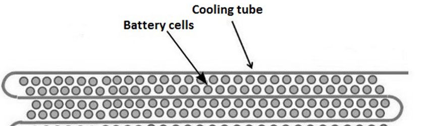
Energies 2017, 10, 1217                                                                             5 of 82

periods, for example, traffic jams. This feature also reduces the GHG emission. When higher speed is
needed, the HEV switches to the ICE. The two drive trains can also work together to improve the
performance. Hybrid power systems are used extensively to reduce or to completely remove turbo
lag in turbocharged cars, like the Acura NSX. It also enhances performance by filling the gaps
between gear shifts and providing speed boosts when required. The ICE can charge up the batteries,
HEVs can also retrieve energy by means of regenerative braking. Therefore, HEVs are primarily ICE
driven cars that use an electrical drive train to improve mileage or for performance enhancement. To
attain these features, HEV configurations are being widely adopted by car manufacturers. Figure 4
shows the energy flows in a basic HEV. While starting the vehicle, the ICE may run the motor as a
generator to produce some power and store it in the battery. Passing needs a boost in speed, therefore
the ICE and the motor both drives the power train. During braking the power train runs the motor
as generator to charge the battery by regenerative braking. While cruising, ICE runs the both the
vehicle and the motor as generator, which charges the battery. The power flow is stopped once the
vehicle stops. Figure 5 shows an example of energy management systems used in HEVs. The one
demonstrated here splits power between the ICE and the electric motor (EM) by considering the
vehicle speed, driver’s input, state of charge (SOC) of battery, and the motor speed to attain
maximum fuel efficiency.

                          (a) Direction of power flow during starting and when stopped.

                      (b) Direction of power flow during passing, braking and cruising.
      Figure 4. Power flow among the basic building blocks of an HEV during various stages of a drive
      cycle. Adapted from [8].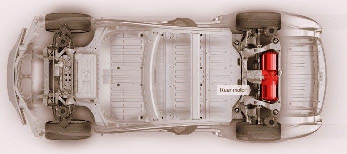
Energies 2017, 10, 1217                                                                              6 of 82

      Figure 5. Example of energy management strategy used in HEV. The controller splits power between
      the ICE and the motor by considering different input parameters. Adapted from [8].

2.3. Plug-In Hybrid Electric Vehicle (PHEV)
     The PHEV concept arose to extend the all-electric range of HEVs [9–14]. It uses both an ICE and
an electrical power train, like a HEV, but the difference between them is that the PHEV uses electric
propulsion as the main driving force, so these vehicles require a bigger battery capacity than HEVs.
PHEVs start in ‘all electric’ mode, runs on electricity and when the batteries are low in charge, it calls
on the ICE to provide a boost or to charge up the battery pack. The ICE is used here to extend the
range. PHEVs can charge their batteries directly from the grid (which HEVs cannot); they also have
the facility to utilize regenerative braking. PHEVs’ ability to run solely on electricity for most of the
time makes its carbon footprint smaller than the HEVs. They consume less fuel as well and thus
reduce the associated cost. The vehicle market is now quite populated with these, Chevrolet Volt and
Toyota Prius sales show their popularity as well.

2.4. Fuel Cell Electric Vehicle (FCEV)
      FCEVs also go by the name Fuel Cell Vehicle (FCV). They got the name because the heart of such
vehicles is fuel cells that use chemical reactions to produce electricity [15]. Hydrogen is the fuel of
choice for FCVs to carry out this reaction, so they are often called ‘hydrogen fuel cell vehicles’. FCVs
carry the hydrogen in special high pressure tanks, another ingredient for the power generating
process is oxygen, which it acquires from the air sucked in from the environment. Electricity
generated from the fuel cells goes to an electric motor which drives the wheels. Excess energy is stored
in storage systems like batteries or supercapacitors [2,3,16–18]. Commercially available FCVs like the
Toyota Mirai or Honda Clarity use batteries for this purpose. FCVs only produce water as a
byproduct of its power generating process which is ejected out of the car through the tailpipes. The
configuration of an FCV is shown in Figure 6. An advantage of such vehicles is they can produce
their own electricity which emits no carbon, enabling it to reduce its carbon footprint further than
any other EV. Another major advantage of these are, and maybe the most important one right now,
refilling these vehicles takes the same amount of time required to fill a conventional vehicle at a gas
pump. This makes adoption of these vehicles more likely in the near future [2–4,19]. A major current
obstacle in adopting this technology is the scarcity of hydrogen fuel stations, but then again, BEV or
PHEV charging stations were not a common scenario even a few years back. A report to the U.S.
Department of Energy (DOE) pointed to another disadvantage which is the high cost of fuel cells,
that cost more than $200 per kW, which is far greater than ICE (less than $50 per kW) [20,21]. There
are also concerns regarding safety in case of flammable hydrogen leaking out of the tanks. If these
obstacles were eliminated, FCVs could really represent the future of cars. The possibilities of using
this technology in supercars is shown by Pininfarina’s H2 Speed (Figure 7). Reference [22] compared
BEVs and FCEVs in different aspects, where FCEVs appeared to be better than BEVs in many ways;
this comparison is shown in Figure 8. In this figure, different costs and cost associated issues of BEV
and FCEV: weight, required storage volume, initial GHG emission, required natural gas energy,
required wind energy, incremental costs, fueling infrastructure cost per car, fuel cost per kilometer,
and incremental life cycle cost are all compared for 320 km (colored blue) and 480 km (colored green)
ranges. The horizontal axis shows the attribute ratio of BEV to FCEV. As having a less value in these
attributes indicates an advantage, any value higher than one in the horizontal axis will declare FCEVs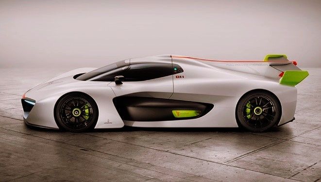
Energies 2017, 10, 1217                                                                                  7 of 82

superior to BEVs in that attribute. That being said, BEVs only appear better in the fields of required
wind energy and fuel cost per kilometer. Fuel cost still appears to be one of the major drawbacks of
FCEVs, as a cheap, sustainable and environment-friendly way of producing hydrogen is still lacking,
and the refueling infrastructure lags behind that of BEVs; but these problems may no longer prevail
in the near future.

      Figure 6. FCEV configuration. Oxygen from air and hydrogen from the cylinders react in fuel cells to
      produce electricity that runs the motor. Only water is produced as by-product which is released in
      the environment.

                     Figure 7. Pininfarina H2 Speed, a supercar employing hydrogen fuel cells.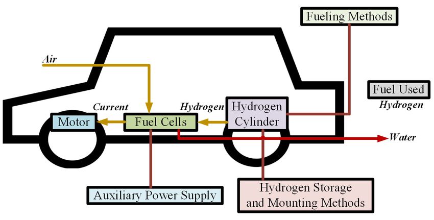
Energies 2017, 10, 1217                                                                                    8 of 82

      Figure 8. Advanced battery EV attribute and fuel cell EV attribute ratio for 320 km (colored blue) and
      480 km (colored green) ranges, with assumptions of average US grid mix in 2010–2020 time-range and
      all hydrogen made from natural gas (values greater than one indicate a fuel cell EV advantage over
      the battery EV). Data from [22].

      Rajashekara predicted a slightly different future for FCVs in [23]. He showed a plug-in fuel cell
vehicle (PFCV) with a larger battery and smaller fuel cell, which makes it battery-dominant car.
According to [23], if hydrogen for such vehicles can be made from renewable sources to run the fuel
cells and the energy to charge the batteries comes from green sources as well, these PFCVs will be the
future of vehicles. The FCVs we see today will not have much appeal other than some niche markets.
Figure 9 shows a basic PFCV configuration. Table 1 compares the different vehicle types in terms of
driving component, energy source, features, and limitations.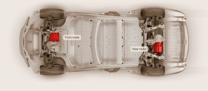
Energies 2017, 10, 1217                                                                                             9 of 82

      Figure 9. PFCV configuration. In addition to the fuel cells, this arrangement can directly charge the
      battery from a power outlet.

                          Table 1. Comparison of different vehicle types. Adapted from [4].

EV Type      Driving Component       Energy Source                Features                           Problems
                                                       • No emission                  •   Battery price and capacity
                                                       • Not dependent on oil         •   Range
                                    • Battery
  BEV       • Electric motor                           • Range depends largely on     •   Charging time
                                    • Ultracapacitor
                                                         the type of battery used     •   Availability of charging stations
                                                       • Available commercially       •   High price
                                                       • Very little emission
                                                       • Long range
                                                       • Can get power from both      • Management of the energy
                                    • Battery
            • Electric motor                             electric supply and fuel       sources
 HEV                                • Ultracapacitor
            • ICE                                      • Complex structure having     • Battery and engine size
                                    • ICE
                                                         both electrical and            optimization
                                                         mechanical drivetrains
                                                       • Available commercially
                                                       • Very little or no emission
                                                       • High efficiency
                                                                                      • Cost of fuel cell
                                                       • Not dependent on supply
 FCEV       • Electric motor        • Fuel cell                                       • Feasible way to produce fuel
                                                         of electricity
                                                                                      • Availability of fueling facilities
                                                       • High price
                                                       • Available commercially

3. EV Configurations
     An electric vehicle, unlike its ICE counterparts, is quite flexible [4]. This is because of the absence
of intricate mechanical arrangements that are required to run a conventional vehicle. In an EV, there
is only one moving part, the motor. It can be controlled by different control arrangements and
techniques. The motor needs a power supply to run which can be from an array of sources. These
two components can be placed at different locations on the vehicle and as long as they are connected
through electrical wires, the vehicle will work. Then again, an EV can run solely on electricity, but an
ICE and electric motor can also work in conjunction to turn the wheels. Because of such flexibility,
different configurations emerged which are adopted according to the type of vehicle. An EV can be
considered as a system incorporating three different subsystems [4]: energy source, propulsion and
auxiliary. The energy source subsystem includes the source, its refueling system and energy
management system. The propulsion subsystem has the electric motor, power converter, controller,
transmission and the driving wheels as its components. The auxiliary subsystem is comprised of
auxiliary power supply, temperature control system and the power steering unit. These subsystems
are shown in Figure 10.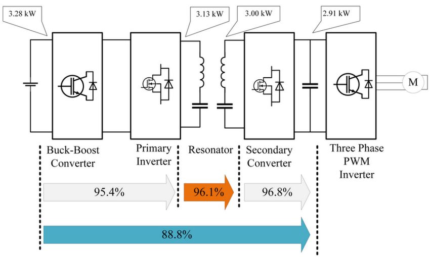
Energies 2017, 10, 1217                                                                        10 of 82

                              Figure 10. EV subsystems. Adapted from [4].

     The arrows indicate the flow of the entities in question. A backward flow of power can be created
by regenerative actions like regenerative braking. The energy source has to be receptive to store the
energy sent back by regenerative actions. Most of the EV batteries along with capacitors/flywheels
(CFs) are compatible with such energy regeneration techniques [4].

3.1. General EV Setup
     EVs can have different configurations as shown in [4]. Figure 11a shows a front-engine front-
wheel drive vehicle with just the ICE replaced by an electric motor. It has a gearbox and clutch that
allows high torque at low speeds and low torque at high speeds. There is a differential as well that
allows the wheels to rotate at different speeds. Figure 11b shows a configuration with the clutch
omitted. It has a fixed gear in place of the gearbox which removes the chance of getting the desired
torque-speed characteristics. The configuration of Figure 11c has the motor, gear and differential as
a single unit that drives both the wheels. The Nissan Leaf, as well as the Chevrolet Spark, uses an
electric motor mounted at the front to drive the front axle. In Figure 11d,e, configurations to obtain
differential action by using two motors for the two wheels are shown. Mechanical interaction can be
further reduced by placing the motors inside the wheels to produce an ‘in-wheel drive’. A planetary
gear system is employed here because advantages like high speed reduction ratio and inline
arrangement of input and output shafts. Mechanical gear system is totally removed in the last
configuration (Figure 11f) by mounting a low-speed motor with an outer rotor configuration on the
wheel rim. Controlling the motor speed thus controls the wheel speed and the vehicle speed.
     EVs can be built with rear wheel drive configuration as well. The single motor version of the
Tesla Model S uses this configuration (Figure 12). The Nissan Blade Glider is a rear wheel drive EV
with in-wheel motor arrangement. The use of in-wheel motors enables it to apply different amount
of torques at each of the two rear wheels to allow better cornering.
Energies 2017, 10, 1217 11 of 82
Figure 11. Different front wheel drive EV configurations. (a) Front-wheel drive vehicle with the ICE
replaced by an electric motor; (b) Vehicle configuration with the clutch omitted; (c) Configuration
with motor, gear and differential combined as a single unit to drive the front wheels; (d) Configuration
with individual motors with fixed fearing for the front wheels to obtain differential action; (e)
Modified configuration of Figure 11d with the fixed gearing arrangement placed within the wheels;
(f) Configuration with the mechanical gear system removed by mounting a low-speed motor on the
wheel rim. Adapted from [4].
Figure 12. Tesla Model S, rear wheel drive configuration [22,24]. (Reprint with permission [24]; 2017,
Tesla.)
For more control and power, all-wheel drive (AWD) configurations can also be used, though it
comes with added cost, weight and complexity. In this case, two motors can be used to drive the front
and the rear axles. An all-wheel drive configuration is shown in Figure 13. AWD configurations are
useful to provide better traction in slippery conditions, they can also use torque vectoring for better
cornering performance and handling. AWD configuration can also be realized for in-wheel motor
systems. It can prove quite useful for city cars like the Hiriko Fold (Figure 14) which has steeringEnergies 2017, 10, 1217 12 of 82
actuator, suspension, brakes and a motor all integrated in each wheel. Such arrangements can provide
efficient all wheel driving, all wheel steering along with ease of parking and cornering.
Figure 13. Tesla Model S, all-wheel drive configuration [24]. (Reprint with permission [24]; 2017,
Tesla.)
Figure 14. Hiriko Fold—a vehicle employing in-wheel motors.
In-wheel motor configurations are quite convenient in the sense that they reduce the weight of
the drive train by removing the central motor, related transmission, differential, universal joints and
drive shaft [25]. They also provide more control, better turning capabilities and more space for
batteries, fuel cells or cargo, but in this case the motor is connected to the power and control systems
through wires that can get damaged because of the harsh environment, vibration and acceleration,
thus causing serious trouble. Sato et al., proposed a wireless in-wheel motor system (W-IWM) in [26]
which they had implemented in an experimental vehicle (shown in Figure 15). Simply put, the wires
are replaced by two coils which are able to transfer power in-between them. Because of vibrations
caused by road conditions, the motor and the vehicle can be misaligned and can cause variation in
the secondary side voltage. In-wheel motor configurations are shown in Figure 16, whereas the
efficiencies at different stages of such a system are shown in Figure 17. In conditions like this,
magnetic resonance coupling is preferred for wireless power transfer [27] as it can overcome the
problems associated with such misalignments [28]. The use of a hysteresis comparator and applying
the secondary inverter power to a controller to counter the change in secondary voltage was also
proposed in [28]. Wireless power transfer (WPT) employing magnetic resonance coupling in a series-
parallel arrangement can provide a transmitting efficiency of 90% in both directions at 2 kW [29].
Therefore, W-IWM is compliant with regenerative braking as well.Energies 2017, 10, 1217 13 of 82
Figure 15. Experimental vehicle with W-IWM system by Sato et al. [26]. (Reprint with permission [26];
2015, IEEE.)
Figure 16. Conventional and wireless IWM. In the wireless setup, coils are used instead of wires to
transfer power from battery to the motor. Adapted from [26].
Figure 17. W-IWM setup showing efficiency at 100% torque reference. Adapted from [26].
3.2. HEV SetupEnergies 2017, 10, 1217 14 of 82
HEVs use both an electrical propulsion system and an ICE. Various ways in which these two can
be set up to spin the wheels creates different configurations that can be summed up in four categories
[4]:
(1) Series hybrid
(2) Parallel hybrid
(3) Series-parallel hybrid
(4) Complex hybrid
3.2.1. Series Hybrid
This configuration is the simplest one to make an HEV. Only the motor is connected to the
wheels here, the engine is used to run a generator which provides the electrical power. It can be put
as an EV that is assisted by an ICE generator [4]. Series hybrid drive train is shown in Figure 18. Table
2 shows the merits and demerits of this configuration.
Figure 18. Drive train of series hybrid system. The engine is used to generate electricity only and
supply to the motor through a rectifier. Power from the battery goes to the motor through a DC-DC
converter [30].
Table 2. Advantages and limitations of series hybrid configuration. Adapted from [8].
Efficient and optimized power-plant
Possibilities for modular power-plant
Optimized drive line
Possibility of swift ‘black box’ service exchange
Advantages
Long lifetime
Mature technology
Fast response
Capable of attaining zero emission
Large traction drive system
Limitations Requirement of proper algorithms
Multiple energy conversion steps
3.2.2. Parallel HybridEnergies 2017, 10, 1217 15 of 82
This configuration connects both the ICE and the motor in parallel to the wheels. Either one of
them or both take part in delivering the power. It can be considered as an IC engine vehicle with
electric assistance [4]. The energy storages in such a vehicle can be charged by the electric motor by
means of regenerative braking or by the ICE when it produces more than the power required to drive
the wheels. Parallel hybrid drive train is shown in Figure 19. Table 3 shows the merits and demerits
of this configuration, while Table 4 compares the series and the parallel systems.
Figure 19. Drive train of parallel hybrid system. The engine and the motor both can run the can
through the mechanical coupling [30].
Table 3. Advantages and limitations of parallel hybrid configuration. Adapted from [30].
Capable of attaining zero emission
Advantages Economic gain
More flexibility
Expensive
Complex control
Limitations
Requirement of proper algorithms
Need of high voltage to ensure efficiency
Table 4. Comparison of parallel and series hybrid configurations. Data from [8].
Parameters Parallel HEV Series HEV
Voltage 14 V, 42 V, 144 V, 300 V 216 V, 274 V, 300 V, 350 V, 550 V, 900 V
Power requirement 3 KW–40 KW >50 KW
Relative gain in fuel economy (%) 5–40 >75
3.2.3. Series-Parallel Hybrid
In an effort to combine the series and the parallel configuration, this system acquires an
additional mechanical link compared to the series type, or an extra generator when compared to the
parallel type. It provides the advantages of both the systems but is more costly and complicated
nonetheless. Complications in drive train are caused to some extent by the presence of a planetary
gear unit [30]. Figure 20 shows a planetary gear arrangement: the sun gear is connected to the
generator, the output shaft of the motor is connected to the ring gear, the ICE is coupled to the
planetary carrier, and the pinion gears keep the whole system connected. A less complex alternative
to this system is to use a transmotor, which is a floating-stator electric machine. In this system the
engine is attached to the stator, and the rotor stays connected to the drive train wheel through the
gears. The motor speed is the relative speed between the rotor and the stator and controlling it adjustsEnergies 2017, 10, 1217 16 of 82
the engine speed for any particular vehicle speed [30]. Series-parallel hybrid drive train with
planetary gear system is shown in Figure 21; Figure 22 shows the system with a transmotor.
Figure 20. Planetary gear system [31].
Figure 21. Drive train of series-parallel hybrid system using planetary gear unit. The planetary gear
unit combines the engine, the generator and the motor [30].Energies 2017, 10, 1217 17 of 82
Figure 22. Drive train of series-parallel hybrid system using transmotor. The planetary gear system is
absent in this arrangement [30].
3.2.4. Complex Hybrid
This system has one major difference with the series-parallel system, that is, it allows
bidirectional flow of power whereas the series-parallel can provide only unidirectional power flow.
However, using current market terminologies, this configuration is denoted as series-parallel system
too. High complexity and cost are drawbacks of this system, but it is adopted by some vehicles to use
dual-axle propulsion [4]. Constantly variable transmission (CVT) can be used for power splitting in
a complex hybrid system or choosing between the power sources to drive the wheels. Electric
arrangements can be used for such processes and this is dubbed as e-CVT, which has been developed
and introduced by Toyota Motor Co. (Toyota City, Aichi Prefecture 471-8571, Japan). CVTs can be
implemented hydraulically, mechanically, hydro-mechanically or electromechanically [32]. Two
methods of power splitting—input splitting and complex splitting are shown in [32]. Input splitting
got the name as it has a power split device placed at the transmission input. This system is used by
certain Toyota and Ford models [32]. Reference [32] also showed different modes of these two
splitting mechanisms and provided descriptions of e-CVT systems adopted by different
manufacturers which are shown in Figures 23 and 24. Such power-split HEVs require two electric
machines, wheels, an engine and a planetary gear (PG), combining all of them can be done in twenty-
four different ways. If another PG is used, that number gets greater than one thousand. An optimal
design incorporating a single PG is proposed in [31]. Four-wheel drive (4WD) configurations can
benefit from using a two-motor hybrid configuration as it nullifies the need of a power transmission
system to the back wheels (as they get their own motor) and provides the advantage of energy
reproduction by means of regenerative braking [33]. Four-wheel drive HEV structure is shown in
Figure 25. A stability enhancement scheme for such a configuration by controlling the rear motor is
shown in [33].Energies 2017, 10, 1217 18 of 82
Figure 23. Input split e-CVT system. Adapted from [32].
Figure 24. Compound split e-CVT system. Adapted from [32].Energies 2017, 10, 1217 19 of 82
Figure 25. Structure for four-wheel drive HEV [32]. This particular system uses a vehicle controller
which employs a number of sensors to perceive the driving condition and keeps the vehicle stable by
controlling the brake control and the motor control units.
4. Energy Sources
EVs can get the energy required to run from different sources. The criteria such sources have to
satisfy are mentioned in [4], high energy density and high power density being two of the most
important ones [30]. There are other characteristics that are sought after to make a perfect energy
source, fast charging, long service and cycle life, less cost and maintenance being a few of them. High
specific energy is required from a source to provide a long driving range whereas high specific power
helps to increase the acceleration. Because of the diverse characteristics that are required for the
perfect source, quite a few sources or energy storage systems (ESS) come into discussion; they are
also used in different combinations to provide desired power and energy requirements [4].
4.1. Battery
Batteries have been the major energy source for EVs for a long time; though of course, was time
has gone by, different battery technologies have been invented and adopted and this process is still
going on to attain the desired performance goals. Table 5 shows the desired performance for EV
batteries set by the U.S. Advanced Battery Consortium (USABC).
Table 5. Performance goal of EV batteries as set by USABC. Data from [4].
Parameters Mid-Term Long-Term
Energy density (C/3 discharge rate) (Wh/L) 135 300
Specific energy (C/3 discharge rate) (Wh/kg) 80 (Desired: 100) 200
Power density (W/l) 250 600
Specific power (80% DOD/30 s) (W/kg) 150 (Desired: 200) 400
Lifetime (year) 5 10
Primary goals
Cycle life (80% DOD) (cycles) 600 1000
Price (USD/kWh)Energies 2017, 10, 1217 20 of 82
Resistance to abuse Tolerance Tolerance
Thermal loss 3.2 W/kWh 3.2 W/kWh
Some of the prominent battery types are: lead-acid, Ni-Cd, Ni-Zn, Zn/air, Ni-MH, Na/S, Li-
polymer and Li-ion batteries. Yong et al., also showed a battery made out of graphene for EV use
whose advantages, structural model and application is described in [34]. Different battery types have
their own pros and cons, and while selecting one, these things have to be kept in mind. In [35],
Khaligh et al., provided key features of some known batteries which are demonstrated in Table 6. In
Table 7, common battery types are juxtaposed to relative advantage of one battery type over the
others.
Table 6. Common battery types, their basic construction components, advantages and disadvantages.
Data from [35–44].
Battery Type Components Advantage Disadvantage
• Cannot discharge more than
• Available in production 20% of its capacity
• Negative active material: spongy
volume • Has a limited life cycle if
lead
• Comparatively low in operated on a deep rate of SOC
Lead-acid • Positive active material: lead
cost (state of charge)
oxide
• Mature technology as • Low energy and power density
• Electrolyte: diluted sulfuric acid
used for over fifty years • Heavier
• May need maintenance
• Double energy density
compared to lead-acid
• Harmless to the
environment
• Electrolyte: alkaline solution • Recyclable
• Reduced lifetime of around
• Positive electrode: nickel • Safe operation at high
200–300 cycles if discharged
NiMH (Nickel- hydroxide voltage
rapidly on high load currents
Metal Hydride) • Negative electrode: alloy of • Can store volumetric
• Reduced usable power because
nickel, titanium, vanadium and power and energy
of memory effect
other metals. • Cycle life is longer
• Operating temperature
range is long
• Resistant to over-charge
and discharge
• High energy density,
twice of NiMH
• Positive electrode: oxidized cobalt • Good performance at
material high temperature • High cost
Li-Ion • Negative electrode: carbon • Recyclable • Recharging still takes quite a
(Lithium-Ion) material • Low memory effect long time, though better than
• Electrolyte: lithium salt solution • High specific power most batteries
in an organic solvent • High specific energy
• Long battery life, around
1000 cycles
• High energy density
• High power density
• Uses low cost material
• Positive electrode: nickel
Ni-Zn (Nickel- • Capable of deep cycle • Fast growth of dendrite,
oxyhydroxide
Zinc) • Friendly to environment preventing use in vehicles
• Negative electrode: zinc
• Usable in a wide
temperature range from
−10 °C to 50 °C
• Cadmium can cause pollution
• Long lifetime
• Positive electrode: nickel in case of not being properly
Ni-Cd (Nickel- • Can discharge fully
hydroxide disposed of
Cadmium) without being damaged
• Negative electrode: cadmium • Costly for vehicular
• Recyclable
applicationEnergies 2017, 10, 1217 21 of 82
Table 7. Cross comparison of different battery types to show relative advantages. Adapted from [45].
Ni-Cd (Nickel- NiMH (Nickel– Li-Ion (Lithium-Ion)
Advantages Over Lead-Acid
Cadmium) Metal Hydride) Conventional Polymer
• Volumetric energy
density • Volumetric • Volumetric energy • Volumetric energy
• Gravimetric energy energy density density density
density • Gravimetric • Gravimetric energy • Gravimetric energy
Lead-acid
• Range of operating energy density density density
temperature • Rate of self- • Rate of self- • Rate of self-discharge
• Rate of self-discharge discharge discharge • Design features
reliability
• Volumetric energy
• Volumetric energy
• Output density
• Volumetric density
voltage • Gravimetric energy
Ni-Cd (Nickel- energy density • Gravimetric energy
• Cost density
Cadmium) • Gravimetric density
• Higher • Rate of self-
energy density • Rate of self-discharge
cyclability discharge
• Design features
• Output voltage
• Volumetric energy
• Volumetric energy density
• Output • Range of operating
density • Gravimetric energy
voltage temperature
NiMH (Nickel- • Gravimetric energy density
• Cost • Cost
Metal Hydride) density • Range of operating
• Higher • Higher cyclability
• Range of operating temperature
cyclability • Rate of self-discharge
temperature • Rate of self-discharge
• Design features
• Volumetric energy
• Range of operating
• Cost • Cost density
temperature
• Safety • Safety • Gravimetric energy
Li-Ion • Cost
• Higher • Rate of density (potential)
(conventional) • Safety
cyclability discharge • Cost
• Higher cyclability
• Re-cyclability • Re-cyclability • Design features
• Recyclability
• Safety
• Volumetric
• Range of operating
• Cost energy density • Range of operating
temperature
Li-Ion (polymer) • Higher • Cost temperature
• Higher cyclability
cyclability • Higher • Higher cyclability
• Cost
cyclability
• Volumetric energy • Volumetric energy
density density
• Gravimetric energy • Gravimetric energy
• Cost • Cost density density
• Volumetric
Absolute advantages • Higher • Range of operating • Range of operating • Range of operating
energy density
cyclability temperature temperature temperature
• Rate of self- • Rate of self-discharge
discharge • Output voltage
• Output voltage • Design features
The battery packs used in EVs are made of numerous battery cells (Figure 26). The Tesla Model
S, for example, has 7104 Li-Ion cells in the 85 kWh pack. All these cells are desired to have the same
SOC at all times to have the same degradation rate and same capacity over the lifetime, preventing
premature end of life (EOL) [46]. A power electronic control device, called a cell voltage equalizer,
can achieve this feat by taking active measures to equalize the SOC and voltage of each cell. The
equalizers can be of different types according to their construction and working principle. Resistive
equalizers keep all the cells at the same voltage level by burning up the extra power at cells with
higher voltages. Capacitive equalizers, on the other hand, transfers energy from the higher energy
cells to the lower energy ones by switching capacitors. Inductive capacitors can be of different
configurations: basic, Cuk, and single of multiple transformer based; but all of them transfer energy
from higher energy cells to the ones with lower energy by using inductors [46–52]. All these
configurations have their own merits and demerits, which are shown in Table 8; the schematics are
shown in Figures 27 and 28. Table 9 shows comparisons between the equalizer types.Energies 2017, 10, 1217 22 of 82
Figure 26. Battery cell arrangement in a battery pack. Cooling tubes are used to dissipate the heat
generated in the battery cells.
(a) (b)
Figure 27. Equalizer configurations: (a) Resistive equalizer, extra power from any cell is burned up in
the resistance; (b) Capacitive equalizer, excess energy is transferred to lower energy cells by switching
of capacitors.
(a) (b)Energies 2017, 10, 1217 23 of 82
(c) (d)
Figure 28. Inductive equalizer configurations: (a) Basic; (b) Cuk; (c) Transformer based; (d) Multiple
transformers based. Excess energy is transferred to lower energy cells by using inductors.
Table 8. Advantages and disadvantages of different equalizer types. Data from [46–52].
Equalizer Type Advantage Disadvantage
• Inherent heating problem
• Low equalizing current (300–500) mA
• Only usable in the last stages of charging
• Cheapest, widely utilized for laptop and flotation
Resistive
batteries • Efficiency is almost 0%
• All equalizing current transforms into heat
for EV application, therefore not
recommended
• Unable to control inrush current
• Better current capabilities than resistive • Potentially harmful current ripples can flow
equalizers for big cell voltage differences
Capacitive
• No control issue • Cannot provide any required voltage
• Simple implementation difference which is essential for SOC
equalization
• Relatively simple
• Capable of transporting high amount of
• Requires additional components to prevent
energy
ripple currents
• Can handle complex control schemes like
• Needs two switches in addition to drivers
voltage difference control and current
Basic Inductive and controls in each cell
limitation
• Current distribution is highly concentrated
• Can compensate for internal resistance of
in neighboring cells because of switching
cells
loss
• Increased equalizing current
• Not dependent on cell voltage
• Additional cost of higher voltage and
current rated switches, power capacitors
• Has all the advantages of inductive • Subjected to loss caused by series capacitor
equalizres • A little less efficient than typical inductive
Cuk Inductive
• Can accommodate complex control and equalizers
withstand high current • Faces problems during distributing
equalizing currents all over the cell string
• May need additional processing power
• Complex transformer with multiple
• Theoretically permits proper current secondary, which is very much challenging
Transformer based
distribution in all cells without addition to mass produce
Inductive
control or loss • Not an option for EV packs
• Cannot handle complex control algorithms
• Still difficult to build with commercial
Multiple transformer • Separate transformers are used which are
inductors without facing voltage and current
based Inductive easier for mass production
imbalanceEnergies 2017, 10, 1217 24 of 82
Table 9. Comparison of equalizers; a ↑ sign indicates an advantage whereas the ↓ signs indicate
drawbacks. Adapted from [46].
Equalizer Equalizer Current Current Current
Manufacture Cost Control
Type Current Distribution Control Ripple
↑↑
Resistive ↓↓ N/A ↑ ↑↑↑ ↑↑↑ ↑↑↑
↑
Capacitive ↓ ↑ ↓↓ ↓↓ ↑↑ ↑↑ ↑↑
Basic
↑↑ ↑ ↑ ↑↑ ↑ ↓ ↓
Inductive
Cuk ↑↑ ↑ ↑ ↑↑↑ ↓ ↓↓ ↓
Transformer ↑ ↑↑↑ ↓↓ ↓↓ ↓↓ ↓↓ ↑↑
Lithium-ion batteries are being used everywhere these days. It has replaced the lead-acid
counterpart and became a mature technology itself. Their popularity can be justified by the fact that
best-selling EVs, for example, Nissan Leaf and Tesla Model S—all use these batteries [53,54]. Battery
parameters of some current EVs are shown in Table 10. Lithium batteries also have lots of scope to
improve [55]. Better battery technologies have been discovered already, but they are not being
pursued because of the exorbitant costs associated with their research and development, so it can be
said that, lithium batteries will dominate the EV scene for quite some time to come.
Table 10. Battery parameters of some current EVs. Data from [5].
Model Total Energy (kWh) Usable Energy (kWh) Usable Energy (%)
i3 22 18.8 85
C30 24 22.7 95
B-Class 36 28 78
e6 61.4 57 93
RAV4 41.8 35 84
4.2. Ultracapacitors (UCs)
UCs have two electrodes separated by an ion-enriched liquid dielectric. When a potential is
applied, the positive electrode attracts the negative ions and the negative electrode gathers the
positive ones. The charges get stored physically stored on electrodes this way and provide a
considerably high power density. As no chemical reactions take place on the electrodes, ultra-
capacitors tend to have a long cycle life; but the absence of any chemical reaction also makes them
low in energy density [35]. The internal resistance is low too, making it highly efficient, but it also
causes high output current if charged at a state of extremely low SOC [56,57]. A UC’s terminal voltage
is directly proportional to its SOC; so it can also operate all through its voltage range [35]. Basic
construction of an UC cell is shown in Figure 29. EVs go through start/stop conditions quite a lot,
especially in urban driving situations. This makes the battery discharge rate highly changeable. The
average power required from batteries is low, but during acceleration or conditions like hill-climb a
high power is required in a short duration of time [4,35]. The peak power required in a high-
performance electric vehicle can be up to sixteen times the average power [4]. UCs fit in perfectly in
such a scenario as it can provide high power for short durations. It is also fast in capturing the energy
generated by regenerative braking [2,35]. A combined battery-UC system (as shown in Figure 30)
negates each other’s shortcomings and provides an efficient and reliable energy system. The low cost,
load leveling capability, temperature adaptability and long service life of UCs make them a likable
option as well [4,30].Energies 2017, 10, 1217 25 of 82
Figure 29. An UC cell; a separator keeps the two electrodes apart [58].
Figure 30. Combination of battery and UC to complement each-other’s shortcomings [59].
4.3. Fuel Cell (FC)
Fuel cells generate electricity by electrochemical reaction. An FC has an anode (A), a cathode (C)
and an electrolyte (E) between them. Fuel is introduced to the anode, gets oxidized there, the ions
created travel through the electrolyte to the cathode and combine with the other reactant introduced
there. The electrons produced by oxidation at the anode produce the electricity. Hydrogen is used in
FCEVs because of its high energy content, and the facts it is non-polluting (producing only water as
exhaust) and abundant in Nature in the form of different compounds such as hydrocarbons [4].
Hydrogen can be stored in different methods for use in EVs [4]; commercially available FCVs like the
Toyota Mirai use cylinders to store it. The operating principle of a general fuel cell is demonstrated
in Figure 31, while Figure 32 shows a hydrogen fuel cell. According to the material used, fuel cells
can be classified into different types. A comparison among them is shown in Table 11. The chemical
reaction governing the working of a fuel cell is stated below:
2H2 + O2 = 2H2O (1)Energies 2017, 10, 1217 26 of 82
Figure 31. Working principle of fuel cell. Fuel and oxygen is taken in, exhaust and current is generated
as the products of chemical reaction. Adapted from [4].
Figure 32. Hydrogen fuel cell configuration. Hydrogen is used as the fuel which reacts with oxygen
and produces water and current as products. Adapted from [35].
Table 11. Comparison of different fuel cell configurations. Data from [2].
PAFC AFC MCFC SOFC SPFC DMFC
Working temp. (°C) 150–210 60–100 600–700 900–1000 50–100 50–100
Power density (W/cm2) 0.2–0.25 0.2–0.3 0.1–0.2 0.24–0.3 0.35–0.6 0.04–0.25
Estimated life (kh) 40 10 40 40 40 10
Estimated cost (USD/kW) 1000 200 1000 1500 200 200
PAFC: Phosphoric acid fuel cell; AFC: Alkaline fuel cell; SOFC: Solid oxide fuel cell; SPFC: Solid
polymer fuel cell, also known as proton exchange membrane fuel cell.
Fuel cells have many advantages for EV use like efficient production of electricity from fuel,
noiseless operation, fast refueling, no or low emissions, durability and the ability to provide high
density current output [24,60]. A main drawback of this technology is the high price. Hydrogen alsoEnergies 2017, 10, 1217 27 of 82
have lower energy density compared to petroleum derived fuel, therefore larger fuel tanks are
required for FCEVs, these tanks also have to capable enough to contain the hydrogen properly and
to minimize risk of any explosion in case of an accident. FC’s efficiency depends on the power it is
supplying; efficiency generally decreases if more power is drawn. Voltage drop in internal resistances
cause most of the losses. Response time of FCs is comparatively higher to UCs or batteries [35].
Because of these reasons, storage like batteries or UCs is used alongside FCs. The Toyota Mirai uses
batteries to power its motor and the FC is used to charge the batteries. The batteries receive the power
reproduced by regenerative braking as well. This combination provides more flexibility as the
batteries do not need to be charged, only the fuel for the FC has to be replenished and it takes far less
time than recharging the batteries.
4.4. Flywheel
Flywheels are used as energy storage by using the energy to spin the flywheel which keeps on
spinning because of inertia. The flywheel acts as a motor during the storage stage. When the energy
is needed to be recovered, the flywheel’s kinetic energy can be used to rotate a generator to produce
power. Advanced flywheels can have their rotors made out of sophisticated materials like carbon
composites and are placed in a vacuum chamber suspended by magnetic bearings. Figure 33 shows
a flywheel used in the Formula One (F1) racing kinetic energy recovery system (KERS). The major
components of a flywheel are demonstrated in Figure 34. Flywheels offer a lot of advantages over
other storage forms for EV use as they are lighter, faster and more efficient at absorbing power from
regenerative braking, faster at supplying a huge amount of power in a short time when rapid
acceleration is needed and can go through a lot of charge-discharge cycles over their lifetime. They
are especially favored for hybrid racecars which go through a lot of abrupt braking and acceleration,
which are also at much higher g-force than normal commuter cars. Storage systems like batteries or
UCs cannot capture the energy generated by regenerative braking in situations like this properly.
Flywheels, on the other hand, because of their fast response, have a better efficiency in similar
scenarios, by making use of regenerative braking more effectively; it reduces pressure on the brake
pads as well. The Porsche 911GT3R hybrid made use of this technology. Flywheels can be made with
different materials, each with their own merits and demerits. Characteristics of some these materials
are shown in Table 12; among the ones displayed in the table, carbon T1000 offers the highest amount
of energy density, but it is much costlier than the others. Therefore, there remains a trade-off between
cost and performance.
Figure 33. A flywheel used in the Formula One racing kinetic energy recovery system (KERS).Energies 2017, 10, 1217 28 of 82
Figure 34. Basic flywheel components. The flywheel is suspended in tis hosing by bearings, and is
connected to a motor-generator to store and supply energy [61].
Table 12. Characteristics of different materials used for flywheels [62].
Density Tensile Strength Max Energy Density Cost
Material
(kg/m3) (mpa) (mj/kg) (USD/kg)
Monolithic
4340 steel 7700 1520 0.19 1
material
E-glass 2000 100 0.05 11
S2-glass 1920 1470 0.76 24.6
Carbon
Composites 1520 1950 1.28 101.8
T1000
Carbon
1510 1650 1.1 31.3
AS4C
Currently, no single energy source can provide the ideal characteristics, i.e., high value of both
power and energy density. Table 13 shows a relative comparison of the energy storages to
demonstrate this fact. Hybrid energy storages can be used to counter this problem by employing one
source for high energy density and another for high power density. Different combinations are
possible to create this hybrid system. It can be a combination of battery and ultracapacitor, battery
and flywheel, or fuel cell and battery [4]. Table 14 shows the storage systems used by some current
vehicles.
Table 13. Relative energy and power densities of different energy storage systems [63].
Storage Energy Density Power Density
Battery High Low
Ultracapacitor Low High
Fuel cell High Low
Flywheel Low High
Table 14. Vehicles using different storage systems.
Storage System Vehicles Using the System
Battery Tesla Model S, Nissan Leaf
Fuel cell + battery Toyota Mirai, Honda Clarity
Flywheel Porsche 911GT3R Hybrid
5. Motors Used
The propulsion system is the heart of an EV [64–69], and the electric motor sits right in the core
of the system. The motor converts electrical energy that it gets from the battery into mechanical
energy which enables the vehicle to move. It also acts as a generator during regenerative action which
sends energy back to the energy source. Based on their requirement, EVs can have different numbersYou can also read