AIR CHECK O2 WATER RESISTANT O2 MONITOR - INSTRUCTION MANUAL - PUREAIRE ...
←
→
Page content transcription
If your browser does not render page correctly, please read the page content below
Air CheckO2
Water Resistant O2 Monitor
Instruction Manual
Part number 99118
PureAire Monitoring Systems, Inc.
1140 Ensell Road
Lake Zurich, Illinois 60047
Phone: 847-726-6000
Fax: 847-726-6051
Toll-Free: 888-788-8050
pureairemonitoring.com
Revision Date: February 10, 2022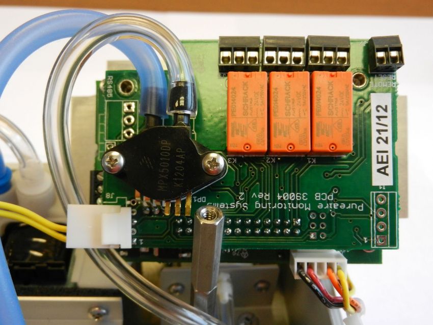
Welcome to PureAire Monitoring Systems

I’d like to thank you for investing in our continuous life safety and process control toxic gas
monitoring systems.

PureAire offers an unbeatable combination of experience and innovation in solving the
safety and environmental needs of our customers. We are capable of providing small
systems of a few points to a total multi-point turnkey computerized package.

PureAire’s proprietary sensor cell technology and state-of-the-art electronics are designed
to interface with the latest distributive or PLC based control systems. We believe that our
experience, innovative products, and commitment to service will satisfy your specific
monitoring needs now and in the future.

Our growth is a result of our total commitment to supporting our customers. We are
available 24 hours a day, 7 days a week to help you when you need us. Our 24-hour
Emergency phone number is 1-847-420-3814. We can provide field service, preventative
maintenance programs and training to your technicians in the operation of our equipment.
Our goal is to provide the best after sale service and support in the industry. That is just
one way PureAire takes that extra step to ensure your complete satisfaction.

Thank you again for investing in PureAire Monitoring Systems for your monitoring needs
and I’m proud to welcome you to our family of valued and satisfied customers.

Sincerely,

Albert A. Carrino
President

Please Read Before Installation
   The following will damage the Air Check Oxygen monitor.

1. The Air Check O2 monitor requires 24 VDC regulated power.
Please Do Not connect the monitor to any voltage that exceeds
24 Volts DC, or ANY AC Voltage.

2. Do not power the Air Check Oxygen monitor with the oxygen sensor
unplugged from the main PC board. Do Not Connect the O2 sensor to
the PC board while the monitor is powered. This Will Damage the O2
sensor.

3. The oxygen sensor cell is matched to the electronics. Never exchange
the electronics with an oxygen sensor from a different monitor.

4. When testing Sample Draw and Ex type monitors use an On Demand
regulator to expose the span gas to the monitor. (see section 6.1.2)

5. Only expose the monitor to span gas blends that consist of Oxygen
and Nitrogen only. Do Not expose the monitor to any combustible
gas, i.e. Methane, Hydrogen, etc. Exposure to combustible span gases
can damage the oxygen zirconium sensor cell.

6. Do not expose the Oxygen monitor to silicone, Freon or corrosive
   compounds. They can cause a loss of sensitivity and damage the
   sensor.

7. When using the Air Check O2 Monitor in wash down areas make sure
you orient the filter with the drain opposite the water flow. (see section
3.2.4)

8. NOTE: If using longer lengths of sample tubing, the dust/water filter
   must be located at the end of the sample line to work properly.

9. The Factory Password for entering the menus is 557
PureAire Monitoring Systems, Inc.

                                                                                                        Table of Contents
1: Introduction ..................................................................................................................... 2
                                   1.1 Key Features ........................................................................ 2
                                   1.2 Component identification .................................................... 3
2: Specifications................................................................................................................... 7
                                   2.1 Performance Specifications ................................................. 7
                                   2.2 Gas Detection System .......................................................... 7
                                   2.3 Signal Outputs ..................................................................... 7
                                   2.4 Electrical Requirements ....................................................... 7
                                   2.5 Physical Characteristics ....................................................... 7
                                   2.6 System Default Factory Settings ......................................... 8
3: Installation ....................................................................................................................... 9
                                   3.1 Site Requirements ................................................................ 9
                                   3.2 Mounting.............................................................................. 9
                                   3.3 Wiring ................................................................................ 13
                                   3.4 Initial Startup ..................................................................... 13
4: Normal Operation .......................................................................................................... 15
                                   4.1 Signal Outputs ................................................................... 15
                                   4.2 Instrument Faults ............................................................... 15
                                   4.3 Routine Maintenance Schedule ......................................... 16
                                   4.4 Loss of Power Indicator ..................................................... 16
                                   4.5 Alarm Reset ....................................................................... 16
5: Air Check O2 Monitor Programming ............................................................................ 18
                                   5.1 Joystick Operation ............................................................. 18
                                   5.2 Program Flowchart ............................................................ 19
                                   5.3 Entering the Password ....................................................... 23
                                   5.4 Changing the User Password ............................................. 24
                                   5.5 Entering the Menus ............................................................ 27
                                         5.5.1 Set 4-20mA Loop ..................................................... 27
                                         5.5.2 Set Formats ............................................................... 29
                                         5.5.3 Set Alarm Threshold Polarity ................................... 31
                                         5.5.4 Set Latching .............................................................. 33
                                         5.5.5 Resetting a Latching Alarm ...................................... 36
                                         5.5.6 Set Alarm Delay ....................................................... 36
                                         5.5.7 Set Zero Suppression ................................................ 37
                                         5.5.8 Set Alarm Thresholds ............................................... 37
                                         5.5.9 Set Alarm Hysteresis ................................................ 39
                                         5.5.10 Set Sensor Adjust .................................................... 40
                                         5.5.11 Main Operation Mode............................................. 41
6: Maintenance & Cell Verification .................................................................................. 42
                                   6.1 Sensor Verification ............................................................ 42
                                   6.2 Sensor Verification Procedure ........................................... 43

7: Appendix ....................................................................................................................... 46
                                                                                                         Rev. 4.08 January 2021

                                                                                                                                            1|Page
PureAire Monitoring Systems, Inc.
1: Introduction
The Air Check O2 water resistant monitor is a self-contained Oxygen deficiency detection system
suitable for remote sampling of confined spaces that require daily wash-downs. It’s a compact gas
monitoring system that’s ideal for the continuous monitoring of inert gas storage areas, confined
spaces, and other locations where low oxygen levels may pose a hazard to personnel. Unlike
electrochemical sensor cells the Air Check O2 zirconium cell provides stable oxygen readings even
in areas where temperature and humidity levels are changing. The PureAire Air Check O2
Deficiency Monitor is suitable for either indoor or outdoor use. Factory calibrated against a NIST
traceable reference standard and UL, CUL and Ce approved.
The heart of the monitoring system is a long-lasting zirconium sensor, which responds to low oxygen
conditions within seconds and provides accurate measurements over a wide temperature and humidity
range. The zirconium O2 sensor cell will operate continuously for 8 or more years and requires an
absolute minimum of maintenance. There are no zero or span calibration pots to adjust and when
compared to disposable type sensors, our long-life zirconium O2 sensor can save up to hundreds of
dollars in annual maintenance.
Ideal for continuously monitoring oxygen levels in food processing areas where inert gases are used in
freezing tunnels, the Air Check water resistant O2 monitor does not drift or loose sensitivity when
the weather or temperature changes. The electronics are housed in a 4X IP65 water resistant housing
capable of withstanding water projected from a nozzle.
Each system consists of a long-life zirconium oxide sensor cell and three-wire transmitter. The Air
Check O2 monitor may be used as a stand-alone gas detector, linked to optional PureAire single and
multipoint controllers, or connected to your own centralized control and surveillance system. This
manual covers the installation, operation, and maintenance of the Air Check water resistant O2
deficiency monitor.
1.1 Key Features
The Air Check O2 monitor incorporates several user-friendly features designed to simplify
installation, operation, and maintenance.
1.1.1 Long Life Zirconium Oxide O2 Sensor
The system’s O2 sensor cell has a life of well over 8 years of continuous operation. Unlike
concentration O2 cells, PureAire’s exclusive zirconium oxide sensor cell does not need an oxygen
reference gas for proper operation. The Air Check O2 monitor can detect low oxygen levels in
confined spaces and process tools without the need of a reference gas.
1.1.2 Smart Electronics
The Air Check O2 monitor incorporates a special electronic circuit that continuously monitors sensor
operation. With the built-in alarm relay, any cell degradation or complete failure will immediately be
detected. This smart circuitry alerts the user to sensor faults and other electrical problems that may
interrupt surveillance through the standard mA signal output signal and through the fault relay.
2|Page
PureAire Monitoring Systems, Inc.
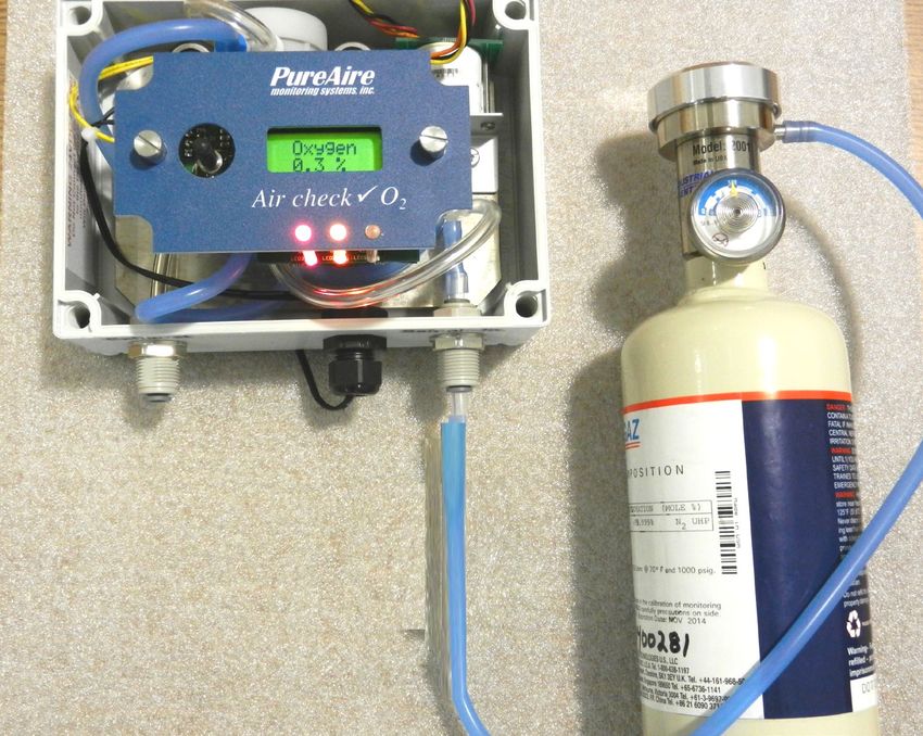
1.1.3 Calibration
The Air Check O2 monitor incorporates a stable zirconium oxide sensor that rarely requires
adjustment. Changing barometric pressure changes or changes in temperature and humidity do
not affect the zirconium oxide oxygen cell. The earth is a wonderful source of calibrated
oxygen at 20.9%, therefore under ambient conditions, visual verification of the Air Check O2
monitor to 20.9% oxygen is easily performed. There are no zero or span pots to adjust. The O2
monitor only requires periodic testing with nitrogen to verify the cells response to low oxygen
levels. See Section 6.2 for the testing procedure to nitrogen.
1.2 Component Identification
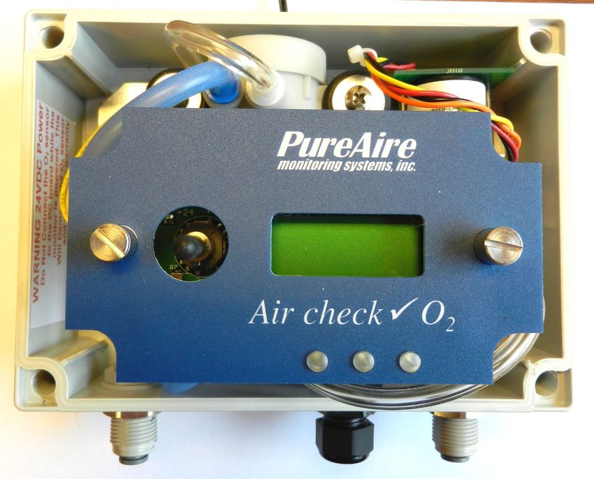
1.2.1 Front View Exterior
Digital Display
Front Cover
Joystick
Front panel
fastening Alarm and Fault
screws (2 ea.) Relays
Front Cover Mounting Feet
Fasteners (4ea.) not shown)
(4ea.)
Sample Sample Inlet
Exhaust
Cable Strain
Relief
1. Front Cover — This is a removable, waterproof cover that protects the
interior of the transmitter. It fastens through 4ea. captive screws
2. Joystick — Used for selecting and adjusting the built-in menus. The Air
Check O2 Sample draw monitor has dual level user selectable alarms.
3. Digital Display — This displays the Oxygen levels in percentage. The
normal oxygen level on earth is 20.9%
4. Front Cover Fasteners— The Air Check O2 Sample draw monitor has
4ea. captive screws to remove the front window from the base unit.
5. Sample Inlet — This inlet permits the flow of oxygen to enter the sensor
cell.
3|Page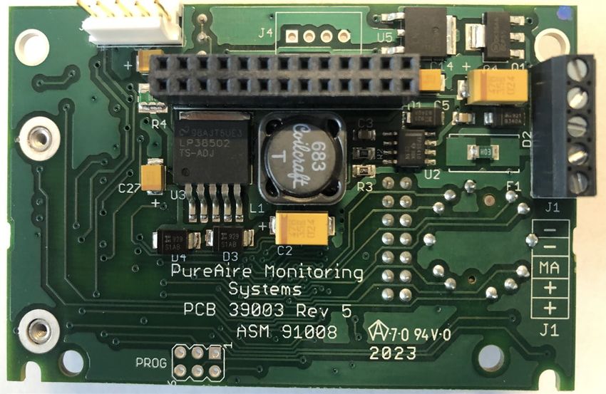
PureAire Monitoring Systems, Inc.

                       6. Sample Exhaust — This permits the flow of oxygen to exit the enclosure.

                       7. Cable strain relief — This is the sealed opening in the transmitter housing
                           for connecting the input power, 4-20 mA output and relay wiring.

               1.2.2 Front View with front cover removed

                                                                                   Oxygen
   Sample                                                                          sensor
   pump                                                                            assembly

                                                                                   Retaining
                                                                                   Screws for
                                                                                   electronics
                                                                                   panel

                                                                                   Alarm Relay
                                                                                   LED’s
   Joystick
                                                                                   Fault

                                                                                   Alarm 1

                                                                                   Alarm 2

                       8. Sample Pump — Used to bring in a sample to the oxygen cell. Flow rate is
                           preset at the factory. Flow rate is continuously protected with a built-in flow
                           sensor. See Section 4.2; Instrument Faults
                       9. Oxygen Sensor Assembly — A zirconium oxide sensor, which detects and
                           measures the level of oxygen. When exposed to oxygen, the sensor outputs
                           an electrical signal proportional to the actual concentration of oxygen.
                       10. Front Panel Retaining Screws — These captive screws are used to mount
                           the display front panel and O2 electronics to the enclosure.
                            NOTE: When unfastening the front panel electronics, apply upwards
                           pressure on the back of the front panel to release the captive screws.
                       11. Alarm Indicators — 3 multi colored LED indicators for showing:
                               Alarm level 1     Orange LED
                               Alarm level 2     Red LED
                               Fault Alarm       Yellow LED

                                                                                                 4|Page
PureAire Monitoring Systems, Inc.

                        O2 water resistant monitor front cover removed

                                                                             Alarm and Fault
                                                                             Relays &
                                                                             Terminal blocks

                                                                             Relays

                                                                             Flow Sensor

                                                                             O2 Sensor
                                                                             connector

                                                                             Sample pump
                                                                             connector

                                                                             Sample Pump

       1.2.3 Transmitter Interior                         2. Sensor cell
                                                          connector

                                                                           1. Power
                                                                           Analog output
                                                                           Terminal Block

                                                                           Common
                                                                           Common
                                                                           mA output
                                                                           + 24 VDC
                                                                           + 24 VDC

                                                                           3. PTC
                                                                           Resettable
                                                                           Fuse

                                                                                      5|Page
PureAire Monitoring Systems, Inc.

                         1. Power Analog Terminal Block — This terminal block is where the 24VDC
                             power and 4-20 mA analog output connection is made.

                         2. Sensor Cell Connector — This connector is where the Oxygen sensor cell
                             is connected. NOTE: Never connect the oxygen sensor to this connector
                             while the monitor is powered. This will damage the oxygen sensor

                         3. PTC Resettable Fuse — The PCB is protected with a PTC Fuse that is
                             resettable and Never needs to be replaced. If it trips, you will need to turn
                             power off to the monitor. When power resumes the fuse will reset.

                         1.2.4    Alarm Relay Board

                             (Identification legend is located between the relay and connector)

                                            Relay 2        Relay 1       Fault Relay          Remote
                                            NC C NO         NC C NO       NC C NO              Reset

Flow Sensor

  Pump
Connector

                                                                                  Sensor cell
                                                                                  Connector
                                                                                                   6|Page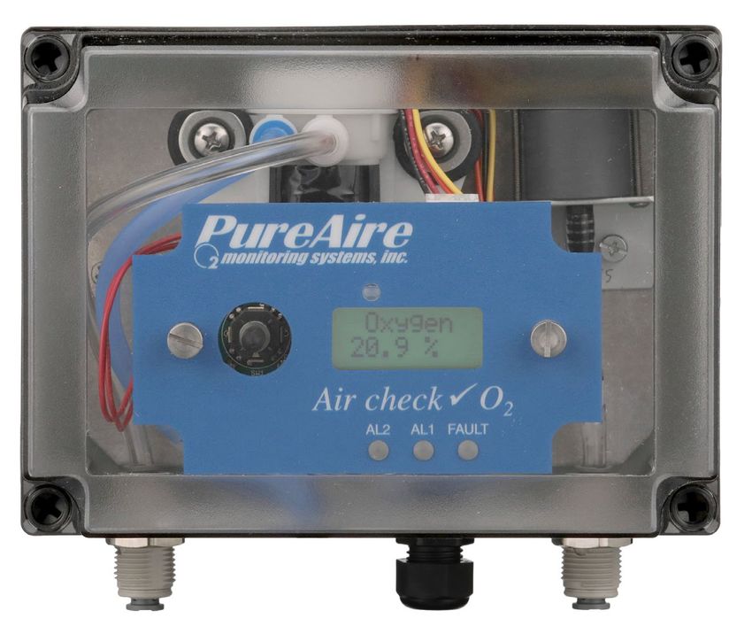
PureAire Monitoring Systems, Inc.

                                                                 2: Specifications
  NOTE: For our continual product improvement, all specifications are subject to change without notice.
2.1 Performance Specifications
Sensor Type:           Long Life Zirconium Oxide Sensor Cell 0-25%
Response Time:         Within 2 seconds of any change in O2.
Repeatability:         ± 2% of reading
Fault Indicators:      Loss of VDC power (analog signal drops to 0 mA).
                       Sensor cell failure: Fault relay activated
Operating Temp:        -40° to 104°F (-40° to +40°C); consult PureAire for lower or higher temperature
Humidity:              0 to 100% RH; IP65 water resistant enclosure
Environment:           Altitude 2000 m, PSU only UL spec. Pollution Degree 3
Sampling distance:     Max distance 100 feet, (33M)
UL / CUL listing:      Measuring Equipment E363306
Ce                     EN 61000-3-2:2006 EMC, EN 61000-3-3:2008 EMC, EN61010-1-3-2013 LVD
2.2 Gas Detection System
Type:                  Long Life Zirconium Oxide Sensor Cell, Range 0-25%
Sensor Life:           8-10 years under normal conditions.
Transmitter:           Microprocessor electronics with built-in 3-digit backlit LCD display
                       Joystick operated menus
2.3 Signal Outputs
Local Display:         Digital display calibrated for Oxygen. The range is stated on the model label
                       and also can be accessed via the joystick on the front panel. In the measurement
                       mode pushing the joystick down will scroll the gas and range on the display.
                       Push the joystick down again to stop the scrolling and display the gas again.
Analog Output:         DC 4-20 mA
Relay Output:          Dual level user selectable alarm relays and one fault relay
                       Rated, 2amps @ 24VAC or 24VDC
2.4 Electrical Requirements
Power:                 24 VDC external power. A regulated 24VDC power supply is required.
Consumption:           Approximately 300mA

2.5 Physical Characteristics
Dimensions:            7.0 (W) x 5.0 (H) x 5.0(D) inches; 178 x 127 x 127 mm
Weight:                4.0 pounds (2 kg)
Enclosure Type:        Polycarbonate wall mount IP65 water resistant. Not intended for explosive
                       atmospheres or electrically classified areas.

                                                                                                7|Page
PureAire Monitoring Systems, Inc.
2.6 AirCheck O2 System Default Factory settings
The Air Check O2 water resistant monitor is shipped with factory defaults for the alarm relay
settings. The following are the factory defaults:
Menu Function Factory Default Menu Defined
Set 4-20mA loop The mA output is set at
Use this function to adjust the
the factory using a
Oxygen monitors 4mA, (Zero) and
calibrated Fluke meter.
20mA, (Span) to your PLC or
distributive control system.
Set Formats Alarm 1 = Normal Do you want the relays to
LED and alarm relay Alarm 2 = Normal energize, (normal) or de-energize,
State ** Fault = Normal (fail safe) when the alarm
activates?
Set Alarm Threshold Alarm 1 = Inverted Do you want to alarm at a level
Polarity Alarm 2 = Inverted higher, (normal) or lower,
Audio = Inverted* (inverted) than the alarm
threshold?
Set Latching Alarm 1 = Non-latching Do you want the alarm to
Alarm 2 = Non-latching automatically reset? (non-latching)
Audio = Non-latching or do you want to manually reset
the alarm? (latching)
Alarm Delay Alarm = 5 seconds How long do you want to wait
until the relay alarms activate?
Zero Suppression 000 = 0.00% This function is Not Enabled on
the Oxygen monitor.
Set Alarm Alarm 1 = 19.5 % At what level do you want to
Thresholds Alarm 2 = 18.0 % alarm?
Audio = 19.5%*
Set Alarm Hysteresis Alarm 1 = 0.0 % For use when using the O2 monitor
Alarm 2 = 0.0 % for control or valves and process.
Audio = 0.0 % See Section 5.5.9
Sensor Adjustment No factory default For use when dynamically gas
calibrating the Oxygen monitor to
a known span gas.
See Section 6.2
Manage Passwords Factory default is 557 For use when changing the
password from factory default to a
new password of your choice.
NOTE: The built-in relay settings may be changed by the user in the field. Refer to
Section 5.4.2
* NOTE: The Audio alarm feature is optional.
** NOTE: The LED indicators on the front panel are connected directly to the alarm
relays.
8|PagePureAire Monitoring Systems, Inc.
3: Installation
3.1 Site Requirements
The Air Check O2 monitor enclosure should be mounted in an area free of vibration and electrical
noise or interference. If possible, avoid areas with high temperatures.
WARNING: The Air Check O2 monitor is not designed for installation in
hazardous areas. Consult PureAire for information on enclosures for use in
hazardous environments.
3.2 Mounting
3.2.1 Transmitter Enclosure
The Air Check O2 monitor is designed primarily for wall mounting and should be installed at a
height convenient for operation, maintenance, and viewing of the instrument display.
3.2.2 Air Check O2 monitor
The transmitter and sensor should be installed in a location where gas leaks are likely to occur or
where released gases may accumulate. It should be mounted no closer than 12 inches above floor level.
Airflow within the monitored area, the characteristics of the gas (lighter or heavier than air), and the
position of workstations and personnel should all be considered in determining the most suitable
installation location.
NOTE: Leave clearance room on the bottom of the Oxygen monitor for the inlet dust/water filter,
which adds an additional 12 inches.
7.0”
12” (approx.)
9|PagePureAire Monitoring Systems, Inc.
3.2.3 Enclosure Mounting Feet
Mounting Feet
Can be oriented in
any direction
Feet can also be
removed for
mounting the O2
monitor flush with
a wall or other
surface
10 | P a g ePureAire Monitoring Systems, Inc.
3.2.4 Air Check Sample Inlet Filter
To protect the pump from dust and water, the use of a special filter is supplied. On installation, attach
the particulate/water filter to the sample inlet by pushing the filter into the ¼” tube compression fitting.
Aligning the arrow, (printed on the filter) towards the monitor. The filter pulls air from both vertical
and horizontal tubes. Never connect any sampling tubing to either tubing ports. When sampling
remote, ALWAYS locate this filter at the end of the sample line.
NOTE: NEVER connect
any tubing to either the
inlet or drain port of the
filter.
Sample air can enter from
either port. This is the
reason why the water
filter must be located at
the end of the sample
line.
The Air Check O2 Sample Draw monitor has an internal sample flow rate that is programmed at the
factory and cannot be changed in the field. A flow sensor on the relay board continually monitors flow
rate for1/2” OD x 3/16” ID tubing up to 100 feet. When a loss of flow is detected, a signal is sent to
the fault relay and the front mounted LED will activate. Sample flow to the monitor is continuously
monitored and controlled by the flow control microprocessor.
NOTE: If using longer lengths of sample tubing, the dust/water filter must be located
at the end of the sample line to work properly.
NOTE: If the sample line is blocked, the fault indicator will illuminate, and the pump will
accelerate to try and reestablish the proper flow rate. If the line is cleared, the pump
will speed and slow down and the fault light will turn off when the flow rate is back to
factory setting. The “Flow Fault” message can be cleared by pushing the joystick down
Depending on the environment, replacement of this filter should be performed every 12 months. In
dusty environments, filter replacement may need to be replaced more frequently. If the filter becomes
completely blocked, the internal flow sensor will detect the loss of flow and activate the fault relay and
LED. Order filter part number 90179
11 | P a g ePureAire Monitoring Systems, Inc.
Photo shown is a
waterproof monitor
located at the risk
site.
If any length of
sample tube is
needed to sample
remote, the water
filter must be located
at the end of the
sample tubing.
¼” tube push to
connect fitting **
Dust/Water Sample
filter p/n 90179
NOTE: NEVER connect
any tubing to either the
inlet or drain port of the
filter.
Sample air can enter from
either port. This is the
reason why the water filter
must be located at the end
of the sample line.
NOTE: When used in wash
**NOTE: PureAire recommends
down areas, the dust/water
the use of polypropylene sample
filter drain must be oriented
tubing with the dimensions of
opposite the water flow.
1/4” OD by 3/16” ID. The total
(i.e, orient the drain towards
length of tubing should not
the back of the monitor to
exceed 100 feet.
prevent water from building up
inside the drain.)
12 | P a g ePureAire Monitoring Systems, Inc.
3.3 Wiring
The Air Check O2 monitor requires a single, 3-wire shielded cable for analog output
and 24 VDC power input. A three-wire shielded cable; 3-conductor, 18 AWG stranded
General Cable E2203S.30.860, or equivalent is recommended for the connection. The
analog out and VDC power in connections are made on the terminal block inside the
transmitter housing.
These connections are made as follows:
- Common
- Common
mA* 4-20mA signal
output to PLC
+ 24VDC Power
+ 24VDC Power
Identification Legend
PureAire provides
the plug-in power
supply
* Caution: DO NOT connect to a powered current loop receiver. The Air Check
Oxygen monitor supplies the current loop power.
3.4
3.3 Initial Startup
Once installation of the gas detector has been completed, it is ready for startup. The following
procedures should be performed before putting the instrument into operation:
1. Check the integrity of all wiring.
2. Apply 24 VDC power to the Power Supply PCB board. The sample pump
will activate. Also, the digital display second line will quickly display the
DTM, (digital transmitter module) serial number and Software version.
NOTE: To display the DTM numbers push the joystick to the left. To display the gas and range
push the joystick down and the gas and range will continuously scroll. To stop the
scrolling, push the joystick down.
The instrument should now be powered up. Upon power up, the Air Check O2 monitor LCD
displays the PureAire logo and then starts a 4-minute, (240 second) count down as the current to the
zirconium oxide O2 sensor stabilizes. The monitor will output a 4 mA signal during the entire warm-
up period. After the countdown, the oxygen sensor will continue to reach its operating temperature for
13 | P a g ePureAire Monitoring Systems, Inc.
approximately 30 minutes and the reading displayed will slowly increase to ambient. Do not make
any adjustments to the reading until after the monitor has been powered for at least an hour.
Oxygen
239 WARM
NOTE: Immediately after the countdown, the monitor will display
“FLOW FAILURE: OUT OF RANGE” on the top line and disappear. This is
a fault history message only and is generated on start-up to verify the integrity of
the system. The message will automatically clear and “Oxygen” will display
on the top line and the “20.9%” reading will display on the bottom line.
If the fault is still present, the actual fault code will display on the bottom line.
The instrument should now be operating properly and is ready for monitoring.
NOTE: The Air Check O2 monitor’s reading may be adjusted to the ambient oxygen level.
See section 6.1 for instructions on adjusting.
Pump Adjustment
The Air Check Sample Draw O2 monitor has a built in digitally controlled flow
controlled sample pump. The pump flow is set at the factory and should not
require adjustment. It has a range to accommodate tubing lengths of 3 feet to
over 100 feet. If flow adjustment is necessary, please contact PureAire.
NOTE: Normal flow rate is 0.25 liters per minute. (250cc/min)
13
14 | P a g ePureAire Monitoring Systems, Inc.
4: Normal Operation
The Air Check O2 monitor is a single point monitor designed for the continuous detection and
measurement of ambient oxygen concentration levels.
4.1 Signal Outputs
The Air Check O2 monitor outputs a continuous 4-20 mA analog signal proportional to the
measured concentration of oxygen. 4 mA represents 0% O2 and 20 mA represents 25% O2 which is the
full range. In the event of a system fault, a specific factory defined code will be displayed on the local
digital display. This code will indicate the exact nature of the system fault. A few codes are listed
below.
CAUTION: DO NOT connect to a powered current loop receiver. The Air Check
Oxygen monitor supplies the current loop power.
4.2 Instrument Faults
The Air Check O2 monitor incorporates a number of self-checking features to
ensure reliable operation. In the event that a fault condition is detected, the
analog output signal is altered: A few common error codes are displayed in the
following table:
Condition Analog Signal
**Supply Voltage Out of Analog output drops to 2 mA
Range Fault code 16
Transmitter cable cut Analog output drops to 0 mA
O2 Cell current fault Analog output drops to 2 mA
Fault Relay activates
Fault Code 128
O2 System Warm Up Analog output drops to 2 mA
Fault Relay activates and turns off when system is
in the Oxygen operation mode
O2 Cell voltage fault Analog output drops to 2 mA
Fault Relay activates
Fault Code 64
No Flow to the Oxygen Analog output drops to 2 mA
sensor Fault Relay activates
Fault Code 32
EEPROM Fault 08 Analog output drops to 2mA
NOTE: All system faults are displayed on the front panel. Each fault has
it’own specific code to identify the specific problem. Please contact PureAire
whenever a fault is displayed.
** When using your own power supply please ensure that the voltage is
regulated to 24VDC +/- 0.5 volts. If the voltage is too low or high you will
activate a “Supply Voltage Out of Range fault and disable the monitor.
15 | P a g ePureAire Monitoring Systems, Inc.
NOTE: If a Fault condition clears itself, (Yellow LED is no longer illuminated)
The Fault message will continue to scroll until manually cleared.
To clear the fault message, push the joystick down (- Minus)
4.3 Routine Maintenance Schedule
Continuous gas detection systems depended upon to measure and detect hazardous gas leaks in the
workplace requires periodic maintenance to ensure proper operation. The frequency with which this
routine maintenance is required depends on the environment. The following table is intended to serve
as a general guideline for routine maintenance. The conditions in your particular application, as well as
your organization’s maintenance policies, will ultimately determine the best routine maintenance
schedule for your equipment. Routine Visual Checks
Items to check Check for power and proper operation
Condition / status when Unit should be outputting a 17.34 mA signal when
operating properly the oxygen level is at 20.9%. The LCD digital
display should also indicate 20.9% 02 when the
oxygen is at ambient levels.
4.3.2 Recommended Routine Maintenance Schedule
Routine Visual Checks Every 6 - 12 months
Sensor Verification with nitrogen Every 6 - 12 months**
** The ambient oxygen level is 20.9%; therefore, under ambient conditions visual verification of the
Air Check O2 monitor to 20.9% oxygen is easily performed. The O2 monitor only requires periodic
testing with nitrogen to verify the cells response to low oxygen levels. See Section 5.5.10 for how to
make minor adjustments.
4.4 Loss of Power Indicator
In the event the Air Check O2 monitor loses 24VDC power, the 4-20 mA analog output signal drops
to 0mA. The LCD display will also display a blank screen.
4.5 Alarm Reset
It the Air Check O2 monitor is supplied with the optional alarm relays, whenever the monitors alarms
are activated, the built-in alarm relays, panel mounted LED’s and optional audio horn will also
activate. When the relay settings are non-latching, the alarm relays, LED’s and horn will automatically
reset. If the relay settings are latching, then a manual reset of the alarms are required. Resetting the
alarms can be performed through use of the joystick or using the remote reset function.
16 | P a g ePureAire Monitoring Systems, Inc.
Joystick – You must enter the password to enter the reset function. After the password is entered and
accepted, push the joystick in; (enter) to reset the alarms.
Remote Reset – Refer to section 1.2.4. for location on PC board. The alarm relay board has a two-pin
connector for wiring to a remote switch. When connected to a switch, this remote reset will bypass the
joystick and a password will not be needed to reset the alarms.
NOTE: The oxygen levels must recover above the alarm thresholds before the horn can be
reset from the remote reset switch or joystick.
17 | P a g ePureAire Monitoring Systems, Inc.
5: Air Check O2 Monitor Programming
The Air Check O2 Deficiency Monitor is supplied with user selectable settings to adjust the
alarm settings, 4 and 20mA output and minor sensor adjustments. The settings are arranged in
menus that are accessed by moving the joystick. To access the menus a factory set password is
used.
NOTE: The Air Check O2 Deficiency Monitor will continuously monitor oxygen while
accessing the menus. The alarm, fault relays and mA output are all active and online while
making any changes to the menus.
5.1 Joystick Operation
The Air Check O2 monitor uses an 8-position joystick with a center pushbutton for selecting
menus and changing values. The joystick is programmed to standard protocol as follows:
NOTE: The joystick has a built-in delay to prevent accidental tampering of the menus.
deliberate entries are required.
CAUTION: Only qualified personnel should perform programming, maintenance and sensor
verification
+ Plus
Previous Next
- Minus
Plus – Pushing the joystick in this direction increases the value
Minus – Pushing the joystick in this direction decreases the value
Next – Pushing the joystick in this direction moves you to the next level of the menu hierarchy.
Previous – Pushing the joystick in this direction takes you out to the last level of menu hierarchy.
Enter – Pushing the joystick directly in the center enters the information into the microprocessor
18 | P a g ePureAire Monitoring Systems, Inc.
5.2 Program Flowchart
Oxygen Enter PassCode OK
557
20.9% Password
Set 4-20mA Set 4mA
PassCode OK
loop Zero 255
Set 20mA
255
Span NOTE: All
numerical values
shown are only
examples and are
not Factory
Force loop Not available Defaults
Format
Set Formats Normal
Relay 1
Invert
Format
Relay 2 Normal
Invert
Format
Fault Relay Normal
Invert
19 | P a g ePureAire Monitoring Systems, Inc.
Set Alarm Set Alarm 1
PassCode OK Threshold Polarity Normal
Polarity
Invert
Set Alarm 2
Polarity Normal
Invert
Set Audio
Alarm Not available
Polarity
Set Latching Set Latching
Relay 1 Nonlatch
NOTE: All
Latch numerical
values
shown are
Set Latching only
Relay 2 Nonlatch
examples
and are not
Factory
Latch Defaults
Set Latching
Audio Not Available
Alarm Delay
005
20 | P a g ePureAire Monitoring Systems, Inc.
* NOTE: Zero
suppression
Zero function is not
PassCode OK available for
Suppressio 000 *
Oxygen
Set Alarm Set Relay 1
19.5%
Thresholds Alarm
Set Relay 2
Alarm 18.0%
Set Audio
Alarm 19.5%
Set Alarm Set Alarm 1 NOTE: All
0.0% numerical
Hysteresis Hysteresis
values shown
are only
examples
and are
Not Factory
Set Alarm 2 0.0% Defaults
Hysteresis
Set Audio
Alarm 0.0%
Hysteresis
Sensor Set sensor 055
Adjustment span
Set Module Not Available **
zero
21 | P a g ePureAire Monitoring Systems, Inc.
Manage Enter New
PassCode OK User A
Passwords
Password
Enable User
Enabled
Password
Disabled
Reset User
Password Not Available
22 | P a g ePureAire Monitoring Systems, Inc.
5.3 Entering the Password
The Air Check Oxygen monitor is supplied with a factory set password to prevent unauthorized access
to the menus. The Password is 557. The following explains how to enter the password.
1. Push the joystick once to the right. Enter Password will scroll on the first line of the digital
display. The second line will still display the current oxygen level.
..Enter password…
20.9 %
2. Push the joystick again once more to the right to enter the input screen. The letter A will
appear and flash.
A
20.9%
NOTE: The display has characters that start with A through Z and 0 through 9.
Pushing the joystick up or down will permit you to scroll through the
alphanumeric characters.
3. Push the joystick up or down to enter the first digit. The display is an alphanumeric display and
toggles from A through Z followed by 0 to 9. The character to be entered will flash.
5
20.9%
4. Push the joystick again to the right to select the second entry. Push the joystick up or down to
select the second digit. The character being entered will flash and the first character entered
will remain lit.
55
20.9%
5. Push the joystick again to the right to select the third entry. Push the joystick up or down to
select the third and final digit. The character being entered will flash and the first and second
characters entered will remain lit. You are now ready to enter the 3-digit password.
557
20.9%
6. Push the joystick in the center to enter the password. If you entered it correctly the display will
scroll Password OK.
...PassCode OK……
20.9%
NOTE: If an incorrect password has been entered, the display will indicate Password
Failed. Push the joystick to the left to access the monitoring mode. From this mode you
can reenter the password again.
23 | P a g ePureAire Monitoring Systems, Inc.
5.4 Changing the User Password
The Air Check Oxygen monitor is supplied with a factory set password to prevent unauthorized access
to the menus. The user can change this password and the following explains how to change the
password.
1. Push the joystick down to access the Manage Passwords Menu. Manage Passwords will
scroll on the first line of the digital display. The second line will still display the current oxygen
level.
..Manage Passwords…
20.9%
2. Push the joystick to the right to enter the input screen. Enter New User Password will scroll
on the first line of the digital display
…Enter New User Password…
20.9 %
3. Push the joystick to the right to enter the input screen. The letter A will appear and flash.
A
20.9%
NOTE: The display has characters that start with A through Z and 0 through 9.
Pushing the joystick up or down will permit you to scroll through the
alphanumeric characters.
4. Push the joystick up or down to enter the first digit. The display is an alphanumeric display and
toggles from A through Z followed by 0 to 9. The character to be entered will flash.
2
20.9%
5. Push the joystick again to the right to select the second entry. Push the joystick up or down to
select the second digit. The character being entered will flash and the first character entered
will remain lit.
25
20.9%
24 | P a g ePureAire Monitoring Systems, Inc.
6. Push the joystick again to the right to select the third entry. Push the joystick up or down to
select the third and final digit. The character being entered will flash and the first and second
characters entered will remain lit. You are now ready to enter the 3-digit password.
253
20.9%
7. Push the joystick in the center to enter the password. This will display the next command,
Re-Enter New Password
…Re-Enter New Password...
20.9 %
8. Push the joystick to the right to enter the input screen. The letter A will appear and flash.
A
20.9%
9. Push the joystick up or down to enter the first digit. The display is an alphanumeric display and
toggles from A through Z followed by 0 to 9. The character to be entered will flash.
2
20.9%
10. Push the joystick again to the right to select the second entry. Push the joystick up or down to
select the second digit. The character being entered will flash and the first character entered will
remain lit.
25
20.9%
11. Push the joystick again to the right to select the third entry. Push the joystick up or down to
select the third and final digit. The character being entered will flash and the first and second
characters entered will remain lit. You are now ready to enter the 3-digit password.
253
20.9%
12. Push the joystick in the center to enter the password. If you entered it correctly the display
will scroll “New Password Entry OK”.
25 | P a g ePureAire Monitoring Systems, Inc.
…New Password Entry OK…
20.9%
NOTE: If on the second entry the password entered was not the same as the first, the display will
take you back to the “Re-enter Password Screen”. You will need to repeat steps 2 through 11. If
you do not enter the password correctly, the monitor remembers the last password that was
properly input.
If you misplace or loose your password, contact PureAire with the monitors DTM# for
instructions on recovering your password. The DTM# is displayed by moving the joystick to
the left.
5.4.1 Enable User Password
This menu permits the user to activate or disable the password function on the Oxygen
monitor. Push the joystick down. “Enable User Password” will scroll on the first line
of the digital display
…Enable User Password…
20.9%
Push the joystick right to display the status. If enabled it will display ”Enabled”
Enabled
20.9%
Push the joystick up or down to change the status. Once enabled or disabled is selected,
Push the joystick in the center to enter the new status. If correctly entered the display
will scroll “Enable User Password”
…Enable User Password…
20.9%
5.4.2 Reset User Password
This menu permits you to reset the password back to 557, as set at the factory.
…Reset User Password…
20.9%
Push the joystick right to display the menu, “Reset to factory Default”.
…Password Reset to factory Default…
20.9%
26 | P a g ePureAire Monitoring Systems, Inc.
Push the joystick in, (like a doorbell) to reset the password back to 557.
Push the joystick left 4 times to go back to the measuring mode.
NOTE: If you lose your password Oxygen
please contact PureAire with your 20.9%
serial number or DTM
5.5 Entering number
the Menus
5.5 Entering the Menus
The Air Check O2 monitor is supplied with main menus with sub menus to adjust mA outputs, alarm
relay settings, sensor adjustments and zero suppression for toxic and corrosive gas sensor cells.
5.5.1 Set 4-20mA loop
.Set 4-20mA loop..
20.9%
This main menu will permit the adjusting of the 4mA and 20mA output from the Air
Check O2 Monitor. It also provides a function that will send an actual output between
4mA and 20 mA to test any remote control and alarm system attached to the O2
monitor.
NOTE: To read the mA output, Air Check O2 monitor must either be connected to a
remote PLC controller or SCADA system. You can also connect the Air Check O2
monitor to a voltmeter to read the mA output. Please consult PureAire for more
information.
From this main menu, pushing the joystick to the right will select the sub menu and the
digital display will scroll the following:
..Set 4mA zero…
20.9%
This is the menu at which to adjust the 4mA output being sent from the Air Check O2
Monitor.
To change this value, push the joystick right to display the 4 mA setting. The display
will indicate a value between 0 and 255 counts. Pushing the joystick up increases the
value and pushing the joystick down decreases the value. The 4mA output being sent
from the Air Check O2 monitor will change as the number on the digital display
changes. Press ENTER to accept the value.
255
20.9%
27 | P a g ePureAire Monitoring Systems, Inc.
Push the joystick to the left brings you back to the pervious Main menu. The digital
display will scroll the following:
...Set 4mA zero…..
20.9%
Push the joystick down to access the next sub menu; Set 20mA Span will scroll.
...Set 20mA Span…
20.9%
This is the menu at which to adjust the 20mA output being sent from the Air Check O2
Monitor.
To change this value, push the joystick right to display the 20mA span setting. The
display will indicate a value between 0 and 255 counts. Pushing the joystick up
increases the value and pushing the joystick down decreases the value. The 20mA
output being sent from the Air Check O2 monitor will change as the number on the
digital display changes. Press ENTER to accept the value.
255
20.9%
Push the joystick to the left brings you back to the pervious Main menu. The digital
display will scroll the following:
...Set 20mA span…..
20.9%
Push the joystick down to access the next sub menu; Force loop will scroll.
.…Force Loop….
20.9%
NOTE: The Force Loop function is not available on the Air Check O2 monitor.
It was designed for toxic and corrosive gases.
This is the sub menu is only used on PureAire’s toxic and corrosive monitors.
…Not Available..
20.9%
Push the joystick to the left brings you back to the pervious menu. The digital display
Will scroll the following:
...Force Loop…..
20.9%
28 | P a g ePureAire Monitoring Systems, Inc.
5.5.2 Set Formats
This is the menu at which to adjust the relay states for the two gas alarm relays and
the individual instrument fault relay.
NOTE: The O2 system must have the relay module installed to access this menu. If
no relay module is installed the display will indicate N/A, (not available)
Push the joystick down to access the next main menu, Set Formats. The display will
scroll the following:
…Set Formats…
20.9%
This menu will permit the setting of the two alarm relays and the fault relay settings
from normally de-energized state, Normal, to normally energized state, Inverted.
From this main menu, pushing the joystick to the right will select the sub menu and the
digital display will scroll the following:
..Format Relay 1…
20.9%
This is the menu at which to adjust the first level alarm relay state on the Air Check
O2 Monitor.
To change this value, push the joystick right to display the relay state. The display will
Indicate INVERT. Pushing the joystick down will change the relay state from INVERT
to NORMAL. Press ENTER to accept the value.
INVERT
20.9%
NORMAL
20.9%
After entering the relay state the display will default back to the Set Formats menu.
The display will scroll the following:
..Set Formats…
20.9%
29 | P a g ePureAire Monitoring Systems, Inc.
From this main menu, pushing the joystick to the right will select the sub menu and the
digital display will scroll the following:
..Format Relay 1…
20.9%
Push the joystick down to access the next main menu, Set Formats. The display will
scroll the following:
… Format Relay 2..
20.9%
This is the menu at which to adjust the second level alarm relay state on the Air Check
O2 Monitor.
To change this value, push the joystick right to display the relay state. The display will
Indicate INVERT. Pushing the joystick down will change the relay state from INVERT
to NORMAL. Press ENTER to accept the value.
INVERT
20.9%
NORMAL
20.9%
After entering the relay state the display will default back to the Set Formats menu.
The display will scroll the following:
..Set Format …
20.9%
From this main menu, pushing the joystick to the right will select the sub menu and the
digital display will scroll the following:
..Format Relay 1…
20.9%
Push the joystick twice to select the fault relay to be adjusted. The display will scroll;
Format Fault Relay.
30 | P a g ePureAire Monitoring Systems, Inc.
..Format Fault Relay...
20.9%
This is the menu at which to adjust the fault alarm relay state on the Air Check
O2 Monitor.
To change this value, push the joystick right to display the relay state. The display will
Indicate INVERT. Pushing the joystick down will change the relay state from INVERT
to NORMAL. Press ENTER to accept the value.
INVERT
20.9%
NORMAL
20.9%
After entering the relay state the display will default back to the Set Formats menu.
The display will scroll the following:
..Set Formats...
20.9
5.5.3 Set Alarm Threshold Polarity
Alarm Threshold Polarity determines if an alarm concentration is set above or below a
threshold value. For example, if an alarm of 19.0% for Oxygen is selected, the Alarm
Threshold Polarity must be set to Invert for the monitors alarm to activate when the
reading goes below 19.0%. For toxic and corrosive gases selecting a Normal setting
for the Alarm Threshold Polarity means that the system will alarm when the gas
concentration exceeds, goes above, an alarm set point. This menu will permit the
selection of the alarm polarity. To access this menu from the “Set Formats” menu, push
the joystick down to display the Set Alarm Threshold Polarity adjustment menu. This
will scroll on the digital display.
..Set Alarm Threshold Priority..
20.9%
Push the joystick right to access the first sub menu; Set Alarm 1 Polarity will
scroll on the display. This is the menu at which to adjust the first level alarm polarity
state on the Air Check O2 Monitor.
..Set Alarm 1 Polarity...
20.9% 31 | P a g ePureAire Monitoring Systems, Inc.
To change this value, push the joystick right to display the relay state. The display will
Indicate INVERT. Pushing the joystick down will change the relay state from INVERT
to NORMAL. Press ENTER to accept the value.
INVERT
20.9%
NORMAL
20.9%
After entering the relay state the display will default back to the Set Alarm 1 Polarity
menu. The display will scroll the following:
..Set Alarm Polarity..
20.9%
Push the joystick down to access the next sub menu; Set Alarm 2 Polarity will scroll
on the display. This is the menu at which to adjust the second level alarm polarity state
on the Air Check O2 Monitor.
..Set Alarm 2 Polarity ..
20.9%
To change this value, push the joystick right to display the relay state. The display will
Indicate INVERT. Pushing the joystick down will change the relay state from INVERT
to NORMAL. Press ENTER to accept the value.
INVERT
20.9%
NORMAL
20.9%
After entering the relay state the display will default back to the Set Relay 2 Alarm
Threshold menu. The display will scroll the following:
..Set Alarm 2 Polarity..
20.9%
Push the joystick down to access the next sub menu; Set Audio Alarm Polarity will
scroll on the display. This is the menu at which to adjust the second level alarm polarity
state on the Air Check O2 Monitor.
32 | P a g ePureAire Monitoring Systems, Inc.
..Set Audio Alarm Polarity...
20.9%
NOTE: The O2 system must have the audio alarm option module installed to access
this menu. If this option is installed the display will indicate N/A, (not available)
NOTE: The optional built-in horn is designed to operate in only one alarm
mode. It will activate in either a decreasing alarm or an increasing
alarm mode only. The horn activation is immediate any time an
alarm threshold is exceeded.
To change this value, push the joystick right to display the relay state. The display will
Indicate INVERT. Pushing the joystick down will change the relay state from INVERT
to NORMAL. Press ENTER to accept the value.
INVERT
20.9%
NORMAL
20.9%
AUTO
20.9%
Auto Mode - The auto mode is used when you wish the horn to activate at the same
time the relays activate. In the Normal or Inverted Mode, the horn
immediately activates any time the alarm thresholds are exceeded. To
activate the horn when the relays activate, choose the AUTO mode.
After entering the relay state the display will default back to the Set Audio Alarm
Polarity menu. The display will scroll the following:
..Set Audio Alarm Polarity...
20.9%
5.5.4 Set Latching
This is the menu at which to adjust the relay alarm state for the two gas alarm relays and
the individual instrument fault relay. The selection permits setting the relays to a
latching or non-latching state. In a latching state, the relay will remain activated until
the user manually selects the Enter Key. In a non-latching state, the alarm relay will
automatically reset once the gas concentration has returned to 20.9% for oxygen.
33 | P a g ePureAire Monitoring Systems, Inc.
NOTE: The O2 system must have the relay module installed to access this menu. If
no relay module is installed the display will indicate N/A, (not available)
.Set Latching…
20.9%
This menu will permit the setting of the two alarm relays and the fault relay settings
from a latching to a non latching state when they are activated.
From this main menu, pushing the joystick to the right will select the sub menu and the
digital display will scroll the following:
..Set Latching Relay 1…
20.9%
This is the menu at which to adjust the first level alarm relay state on the Air Check
O2 Monitor.
To change this value, push the joystick right to display the relay state. The display will
Indicate LATCH. Pushing the joystick down will change the relay state from
LATCHING to NON-LATCHING. Press ENTER to accept the value.
LATCHING
20.9%
NONLATCH
20.9%
After entering the relay state, the display will default back to the Set Latching menu.
The display will scroll the following:
..Set Latching.…
20.9%
From this main menu, pushing the joystick to the right will select the sub menu and the
digital display will scroll the following:
..Set Latching Relay 1…
20.9%
34 | P a g ePureAire Monitoring Systems, Inc.
Push the joystick down to select the next relay to be adjusted. The display will scroll
the following, Set Latching Relay 2.
..Set Latching Relay 2…
20.9%
This is the menu at which to adjust the second level alarm relay state on the Air Check
O2 Monitor.
To change this value, push the joystick right to display the relay state. The display will
Indicate LATCHING. Pushing the joystick down will change the relay state from
LATCHING to NONLATCH. Press ENTER to accept the value.
LATCHING
20.9%
NONLATCH
20.9%
After entering the relay state, the display will default back to the Set Latching menu.
The display will scroll the following:
..Set Latching….
20.9%
From this main menu, pushing the joystick to the right will select the sub menu and the
digital display will scroll the following:
..Set Latching Relay 1…
20.9%
Push the joystick twice to select the Audio Alarm relay to be adjusted. The display will
scroll; Set Latching Audio Alarm.
..Set Latching Audio Alarm…
20.9%
This is the menu at which to adjust the Audio alarm relay state on the Air Check
O2 Monitor.
35 | P a g ePureAire Monitoring Systems, Inc.
NOTE: The O2 system must have the audio alarm option module installed to access
this menu. If this option is installed the display will indicate N/A, (not available)
To change this value, push the joystick right to display the relay state. The display will
Indicate LATCHING. Pushing the joystick down will change the relay state from
LATCHING to NONLATCH. Press ENTER to accept the value.
LATCH
20.9%
NONLATCH
20.9%
After entering the fault relay state the display will default back to the Set Latching
menu. The display will indicate the following:
..Set Latching.…
20.9%
5.5.5 Resetting a Latching Alarm
To reset a latching alarm relay, you must enter the password correctly and then push the
joystick down to enter the reset command. The Oxygen monitor also has an internal
2-pin terminal block for connecting a remote reset switch. (See Alarm Relay board,
section 1.2.7)
5.5.6 Set Alarm Delay
Push the joystick down to access the next main menu, Alarm Delay. The display will
scroll the following:
…Alarm Delay…
20.9%
This is the amount of time an alarm level concentration of oxygen must be present
before the instrument’s gas concentration alarm(s) will be activated. This menu will
permit setting a user selected time delay for activating alarm relays 1 and 2. You can
select from 0 seconds up to 255 seconds after an alarm level has been exceeded before
the alarm relays to activate.
To change this value, push the joystick right to display the time screen. The display will
indicate a value between 0 and 255 seconds. Pushing the joystick up increases the value
and pushing the joystick down decreases the value. Press ENTER to accept the value.
36 | P a g ePureAire Monitoring Systems, Inc.
005
20.9%
After entering the alarm delay, the display will default back to the Alarm Delay menu
and the display will scroll the following:
…Alarm Delay…
20.9%
NOTE: The alarm delay is only available for alarms 1 and 2. There is no delay for
the fault relay. Any system fault will immediately activate the Fault Relay.
5.5.7 Set Zero Suppression
This function not used on the Oxygen monitor. It is only used to decrease the
sensitivity of selected gas sensors. Although the menu permits the changing of settings,
it is totally disabled in the Oxygen monitor. The factory default is set at 000.
NOTE: This function is not available on the Air Check Oxygen monitor.
…Zero Suppression…
000
5.5.8 Set Alarm Thresholds
..Set Alarm Thresholds..
20.9%
This main menu will permit adjusting the oxygen concentration percentage that will
activate alarm levels 1 and 2. If the Audio alarm output module is installed, it will also
permit setting the level at which the audio alarm will activate.
NOTE: To activate the audio alarm, the AirCheck O2 monitor must have the audio
alarm option.
From this main menu, pushing the joystick to the right will select the first sub menu and
the digital display will scroll the following: Set Relay 1 Alarm Threshold.
..Set Relay 1 Alarm Threshold…
20.9%
This is the gas concentration at which the instrument’s first level alarm will be
activated. To change the displayed value, push the joystick to the right to display the
first level alarm setting. The display will indicate a value between 00.0% and 25.5%.
37 | P a g ePureAire Monitoring Systems, Inc.
Pushing the joystick up increases the value and pushing the joystick down decreases the
value. Press ENTER to accept the value.
19.5%
20.9%
After entering the relay state, the display will default back to the Set Relay 1 Alarm
Threshold Menu. The display will scroll the following:
..Set Relay 1 Alarm Threshold…
20.9%
Push the joystick down to access the next sub menu; Set Relay 2 Alarm Threshold,
will scroll on the digital display.
..Set Relay 2 Alarm Threshold…
20.9%
This is the gas concentration at which the instrument’s second level alarm will be
activated. To change the displayed value, push the joystick to the right to display the
second level alarm setting. The display will indicate a value between 00.0% and 25.5%.
Pushing the joystick up increases the value and pushing the joystick down decreases the
value. Press ENTER to accept the value.
18.0%
20.9%
After entering the relay state the display will default back to the Set Relay 2 Alarm
Threshold Menu. The display will scroll the following:
..Set Relay 2 Alarm Threshold…
20.9%
Push the joystick down to access the next sub menu; Set Audio Alarm Threshold,
will scroll on the digital display.
..Set Audio Alarm Threshold…
20.9%
This is the gas concentration at which the instrument’s audio alarm will be activated.
To change the displayed value, push the joystick to the right to display the second level
alarm setting. The display will indicate a value between 00.0% and 25.5%.
19.5% 38 | P a g e
20.9%You can also read