An Introduction to AutoCAD for Beginners
←
→
Page content transcription
If your browser does not render page correctly, please read the page content below

An Introduction to AutoCAD for Beginners

Table of Contents
Introduction to AutoCAD........................................................................... 3
     Upgrading from an Older Version........................................................ 6
     AutoCAD vs. AutoCAD LT................................................................... 7
New Features Overview.............................................................................. 8
     Documentation................................................................................. 11
     Design............................................................................................... 13
     Connectivity...................................................................................... 14
                                                                                                                 Key enhancements
     Customization................................................................................... 15
     Mac Highlights.................................................................................. 16
                                                                                                                 were made in AutoCAD
User Interface Tour................................................................................... 17
Guide to AutoCAD Basics........................................................................ 20
                                                                                                                 around documentation,
     Basics................................................................................................ 22   design, connectivity and
     Viewing............................................................................................. 29
     Geometry.......................................................................................... 31       customization to help
                                                                                                                 create a better user
     Precision............................................................................................ 38
     Layers................................................................................................ 43
     Properties.......................................................................................... 49
     Modifying......................................................................................... 55       experience for Autodesk
     Blocks............................................................................................... 67
     Layouts............................................................................................. 71
                                                                                                                 customers.
     Notes and Labels............................................................................... 77
     Dimensions....................................................................................... 81
     Printing............................................................................................. 86
Additional Resources................................................................................ 91
     Shortcut Keys.................................................................................... 91
     Enhanced Training & Certification Options......................................... 92

                                                                                                                                            2
Introduction to AutoCAD

                          3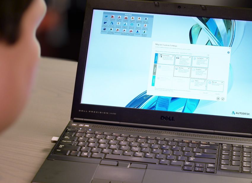
Introduction to AutoCAD
Welcome to AutoCAD’s tutorial. With this suite of tools, you will be
able to produce high quality designs in less time, via the significant
improvements in precision and flexibility while working in both 2D
sketches and 3D modeling.

New Features
Developed based on the feedback from actual users, AutoCAD includes
the features that designers and engineers need in order to do their
best work. Richer design context and more intelligent tools clear the
way to faster, more precise design and documentation. The new smart
dimensioning feature automatically creates appropriate measurements
based on the type of objects you select. For example, angular dimensions
on circles and arcs, dimensions between parallel lines and dimensions
based on Object Snaps. Improvements to the drawing canvas produce
a stunning visual experience that makes navigating the details of your
drawing easier than ever.

AutoCAD is helping users produce
quality designs in less time with
significant improvements.
Documentation has been upgraded, as well. The new Enhanced PDFs
are smaller, faster and smarter, with more searchable content. If you
are bringing a PDF into AutoCAD, there are significant enhancements
to the underlay feature which makes for quicker, more fluid panning

                                                                           4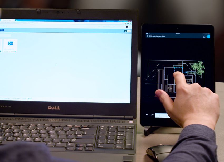
and zooming when working with large files. The new coordination
model feature was introduced to eliminate any unnecessary guesswork.
AutoCAD also lets you confidently share your work using TrustedDWG
technology—the most accurate way to store and share design data.

Platforms and Integration Features
AutoCAD is available for both the Windows and Mac operating systems.
You’ll find mobile solutions support and cloud rendering available to you,
and if you have an AutoCAD subscription, you get access to the latest
version, as well as previous versions, additional support benefits and
cloud rendering in A360.

If you have not yet subscribed, take advantage of AutoCAD’s Free Trial
to learn more about the latest version.

  SUBSCRIBE

  DOWNLOAD FREE TRIAL

                                                                             5
Upgrading from an Older Version
Every product released by Autodesk includes features that are the result
of learnings and feedback provided by our users. The most recent
version of AutoCAD includes improvements such as a new stunning
visual experience, enhanced documentation, and new design features. In
addition, it enables increased connectivity and customizations that allow
users to share designs and customize the user interface.

Some of the recent features that make AutoCAD well worth upgrading
include:

   High-Fidelity lines and curves

   Coordination model

   Point cloud dynamic UCS

   Point cloud geometry extraction

   Smart dimensioning

   Revision cloud enhancements

   PDF enhancements

   Optimized PDF output

   Searchable text in exported PDFs

   Hyperlink support in exported PDFs

   Amplified powerful rendering

   Customization of the user interface

                                                                            6
AutoCAD vs. AutoCAD LT
AutoCAD and its lighter, more streamlined version, AutoCAD LT, are
both leading design and engineering software programs. Both offer 2D
drafting and documentation along with dozens of design, connectivity
and customization features. The primary difference between the
two versions is that AutoCAD capabilities include 3D modeling and
collaboration tools, along with several other special features.

For those unsure which product is right for them, a complete AutoCAD
vs AutoCAD LT comparison is available on the Autodesk website. Or, you
can try AutoCAD and AutoCAD LT for free, if you’d like to get hands-on
information about which product will work best for your projects.

                                                                         7
New Features Overview

                        8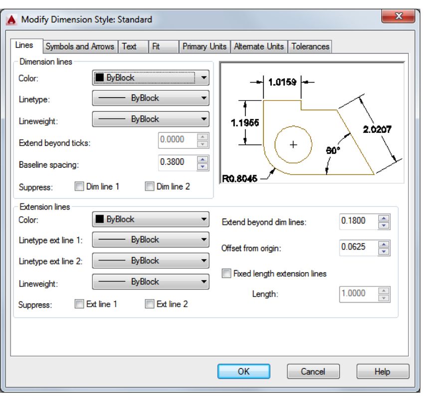
NEW FEATURES OVERVIEW

  New Features Overview
  Key enhancements were made in AutoCAD around                           Intuitive Coordination Modeling
  documentation, design, connectivity and customization. Quite
                                                                         The Attach Coordination Model dialog has the standard insert
  a few of the AutoCAD basics were upgraded to create a better
                                                                         options, such as path, insertion point, scale, and rotation. You can
  user experience for Autodesk customers.
                                                                         also specify whether to show or hide geometry in the model that is
                                                                         the same as the geometry in the current drawing and you’ll be able
  Enhanced Features                                                      to use standard navigation commands like 3DORBIT to navigate
                                                                         the attached coordination model. We added settings for color and
  A new geometric object snap has been added so you can snap
                                                                         opacity fading to make it easier to tell the difference between your
  to the centroid of a closed polygon. Command preview has been
                                                                         drawing and the coordination model. Additionally, you can now:
  enhanced to include the blend, erase, scale, street and rotate
  commands. The DIM command has been enhanced to create                     Attach a Navisworks coordination model to a drawing.
  dimensions based on the type of object you select. Preview works

                                                                            Attach a coordination model from BIM 360 Glue to a
  the same for circles and arcs when creating a diameter or radial
                                                                             drawing via the BIM 360 add-on for AutoCAD.
  dimension. You also have the option to switch between Radius
  and Diameter before placing the dimension. Width sizing of               	Take advantage of Point Cloud enhancements which are
  dimension text is also available for adjusting text wrapping.               now automatically detected.

  PDF Options were added to the Plot dialog. PDF Options support           	Find enhanced support for solid objects.
  links to external websites and files based on links added to objects

                                                                            Utilize 3D Object Snaps to snap to inferred edges, corners,
  in the drawing. You can also export bookmarks for sheets and
                                                                             and centerlines of point clouds to assist in modeling while
  named views so you can easily navigate between them when
                                                                             using a point cloud as reference.
  viewing the PDF.

                                                                            Detect planar segments in point clouds using dynamic UCS,
  TrueType® fonts are now searchable in PDFs and their comments.
                                                                             allowing you to draw geometry directly on a point cloud.
  A new CURSORBADGE system variable enables you to control
  the display of cursor badges. The System Variable Monitor lets you       	Via the Extract Section Lines dialog, you’ll be able to specify
  quickly identify changes to key system variables and then set them          settings including layer, color maximum points to process,
  to your preferred values. You can also display notifications when a         and extraction tolerances. When the processing is complete
  system variable has changed.                                                the geometry is created.

                                                                                                                                                9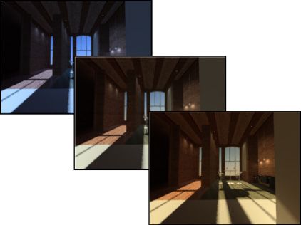
NEW FEATURES OVERVIEW

  Get to Know the New Render Environment
  and Exposure Palette
  The render engine used in earlier releases has been replaced and
  the new Render Environment and Exposure palette allow you to
  apply image-based lighting and adjust photographic exposure
  settings.

  Image-based lighting can be used to brighten a rendered
  image while also improving the contrast to areas with shadows.
  Photographic exposure settings allow you to adjust the exposure
  level of the light in a scene and change the white balance to
  make the lighting appear cooler or warmer in color.

  Once a scene has been configured, you can use the new Render
  Presets Manager palette to specify both the rendering accuracy
  and duration. A rendered image can be generated in the current
  viewport or the Render window, and from there can be saved to
  a raster image file.

                                                                     10
NEW FEATURES OVERVIEW: DOCUMENTATION
Documentation
Documentation, a key feature of any CAD software tool, has Sneak Previews with Smart Dimensioning
been improved greatly in the most recent versions of AutoCAD.
Smart dimensioning is another critical feature and it works by
To accurately turn designs into real world structures, people in
automatically creating appropriate dimension notes based on the
the field rely on accurate documentation. That’s why Autodesk
type of objects you select. Simply pass the cursor over selected
improved the documentation tools in AutoCAD and AutoCAD LT.
objects to see a preview of the dimension before creating it.
Start New Documents or Open Existing Ones
View Changes More Easily with Revision
with the New Tab Page
Clouds
Start on your designs with the New Tab page. Quickly open
Revision clouds help draw attention to specific areas of your
new and existing drawings, and access a large selection of
drawing that are changing. Draw revision clouds around new
design elements. You’ll have the ability to open templates,
changes in a drawing to quickly identify your updates. Easily
update from design feeds, or design data residing on A360
stretch, add to, and remove all parts of existing revision clouds,
project collaboration software. For questions, select the Help
and create revision clouds from almost any object. Whether your
Window, which displays tool locations within the interface via an
revision cloud is rectangular, polygonal, or freehand, it’s now
animated arrow. This function acts as a mini AutoCAD tutorial
easier to edit its size and shape with a grip.
and is a great resource for any questions you may have.
Enjoy Enhanced PDFs A Faster, Cleaner Workspace with Ribbon
Gallery
With Enhanced PDFs, notes and dimensions have been added to
reinforce the use of these PDFs as professional documentation. The Ribbon gallery offers a fast and intuitive workflow for users.
Text is searchable in your PDF, and if you create sheet sets with To add a block to your design, use the Ribbon gallery and hover
hyperlinks to drawings, those links are now maintained. Plotting over the ribbon for a block insertion. The Block gallery will
out a PDF is also quicker, because you have more control over display thumbnails of all the blocks. From there, you can insert
the vector raster and image quality of PDF output. The output is your selection right away without having to use a dialog box.
the same fidelity, at only half the file size.
11NEW FEATURES OVERVIEW: DOCUMENTATION
Save Time with the Command Preview Tool
Another big time saver is the command preview tool, which
helps reduce the number of Undo commands you make by
letting you evaluate the potential changes of commands such
as Offset, Fillet, and Trim. The Intelligent Command Line feature
takes reviews a step further by including AutoCorrect, Adaptive
Suggestions, and Synonym Suggestions. AutoCorrect spellchecks
your input and offers suggestions from a synonym list, so you
never have to see the Command Not Found message.
Since it is much easier to view all of these new features on the
new refined interface, it also helps reduce eyestrain. It’s easier
to see fine lines, buttons, and text, which increases functionality
and productivity. Get the current version of AutoCAD today to
see how all these new features work seamlessly together.
Learn more about the Command Tool here.
12NEW FEATURES OVERVIEW: DESIGN
Design
Lines, arcs and circles are the building blocks used to bring your capture online maps as static images and print them with your
ideas to life. In previous versions of AutoCAD, what you saw on design overlaid, or create PDFs that include the geolocation map.
the screen was not always as crisp as what you plotted to paper.
In this release, you’ll find many design elements that provide a
Shaping Up Shapes in 2D and 3D
stunning visual experience for users.
Isoline curves can now be extracted through a specified point on
a surface or face of a solid to determine the contour lines of any
Clearer Details shape. The tool displays a preview of the resulting spline before
The details in your designs are now viewed more clearly with you pick the point. You can specify the direction of the isolines,
visual enhancements such as Line Fading and enhanced readability either in the U or V direction.
with true curves instead of line segments. With reality computing
Previously you were limited to clicking inside a bounded area to
enhanced, there is now the ability to orient your work more
select multiple objects, but no longer. Now you can select 2D
precisely with the point cloud. Maneuver between horizontal and
and 3D curves for a quick and easy PressPull operation. These 3D
vertical planes more quickly with Dynamic UCS. In addition, snap
free-form design tools help generate design ideas in almost any
to edges, intersections, corners, and centerlines can now be used
form imaginable. PressPull faces, edges, and vertices to model
to quickly create geometry using point cloud object snaps.
complex shapes and add smooth surfaces. Solid, mesh, and
surface modeling give you flexibility and control when designing
Better Integration with Navisworks and BIM in 3D. The navigation bar includes frequently used tools such as
steering wheels, view cube, and show motion, as well as pan,
360 Glue zoom, and orbit.
Another new design feature allows for the ability to paste
If you need to analyze the continuity, curvature, and draft of
Navisworks and BIM 360 Glue models directly inside AutoCAD.
3D solids and surfaces, then the surface tool was made for
This allows users to take advantage of Navisworks’ vast file format
you. The Zebra analysis projects stripes onto a 3D model to
support to bring models into AutoCAD from other applications.
analyze surface continuity. Use the new viewport controls to
Additionally, online maps (formerly live maps) can now be
change viewport settings, views, and visual styles directly on the
accessed directly inside the canvas. This means that you can
viewport canvas.
13NEW FEATURES OVERVIEW: CONNECTIVITY
Connectivity
Collaboration is essential, so making an AutoCAD that helps
designers communicate with other project team members was
essential. The result is an integrated AutoCAD that works across
connected desktop, cloud, and mobile solutions. For example,
you can view, create, edit, and share AutoCAD drawings on a
mobile device or web browser via the AutoCAD 360 mobile and
web app.
The design and the conversation happen in the same place, but
when it’s time to submit your final drawing, you have a choice.
You can keep the comments intact or strip them using built-in
tools in the eTransmit and File Save workflows. TrustedDWG
technology helps ensure that all the elements in your drawings,
and the relationship between those elements, are maintained.
All AutoCAD products use this technology to store and share
design and documentation files.
AutoCAD helps save valuable time by importing models from
Inventor 3D CAD software directly into the AutoCAD model
space environment. You can more easily share and reuse CAD
files with PDF support within AutoCAD software. By using the
materials library, you have access to hundreds of visually rich,
predefined surface materials.
14NEW FEATURES OVERVIEW: CUSTOMIZATION
Customization
Flexibility has always been an AutoCAD virtue. The software’s
open architecture allows for customization that readily adapts to
your needs. Fortunately, if something goes wrong, there is also a
failsafe in the form of a Sysvar monitor. This monitor will prevent
unwanted changes to your system settings, especially if it could
affect your drafting work.
The exchange app was created as a marketplace for general
productivity tools, as well as a place for various applications
for specific disciplines to share information. With this platform,
users can find peer-generated apps and tools that allow them
to use AutoCAD with settings that fit their needs. Designers
and engineers can also easily sync their custom preferences and
support files on multiple machines.
Lastly by offering a customizable and expandable user interface,
companies can expand and change their interface to meet the
needs of their entire company. For help during this process, the
Autodesk Developer Network training and support can answer
questions or help you integrate the latest release of AutoCAD
software into your workflow.
15NEW FEATURES OVERVIEW: MAC HIGHLIGHTS
Mac Highlights
With more enhancements than ever before, AutoCAD’s latest
version on Mac OS can help you and your team be more
productive. Mixed platform team collaboration is easier than
ever with the ability to map XREF file paths from your Mac
to Windows machines, including networked servers. Sending
projects back and forth is easier than ever.
Other features specific to Mac users have been improved
upon, as well. For instance, you can now find high-definition
graphics throughout the user interface from toolbars and
icons to in-canvas line rendering that work beautifully with the
retina display’s high-resolution graphics capabilities. Other Mac
features like multi-touch gestures, overflow navigation, and an
elegant Mac interface have also been improved upon in this
iteration of AutoCAD.
16User Interface Tour
17USER INTERFACE TOUR
User Interface Tour
The AutoCAD user interface was designed to be intuitive and user-friendly. Even if you are at the
beginner’s level for AutoCAD, you should still be able to easily navigate through the software.
Upon first opening the program, you can either start drawing from a template of your
choice, or open a recent document. If there is any product update information (like
the opportunity to get the current version of software), you’ll see it available in the
notifications button. Lastly, you can also log into A360 Connect from this screen.
The drawing area is where you can create and modify objects. This area allows for lots
of flexibility with view cubes, navigation bars, and much more. From this view, you have
many other options to aid in the creative process.
• Viewport controls allow you to adjust both visual styles and views directly on the
viewport canvas.
• Through the navigation bar, you’ll find frequently used tools such as steering wheels,
view cube, and show motion, as well as pan, zoom, and orbit.
• Planar segments can now be detected in point clouds using dynamic UCS tools,
allowing you to draw geometry directly on a point cloud.
• The AutoCAD ribbon gallery offers a fast and intuitive workflow while the quick
access toolbar lets you easily reach the tools you most commonly use.USER INTERFACE TOUR
Command preview helps you reduce the number of Undo commands you make by letting
you evaluate the potential changes of commands such as Offset, Fillet, and Trim. When
you are ready to see your creation in 3D, use the workspace control buttons to get to a
3D workspace.
Customization of the user interface is done by modifying the XML-based customization
(CUIx) file with the Customize User Interface (CUI) Editor. After a command is defined, it
can be used to create a button or a response to an action in the drawing area. Default
shortcut keys are available for your reference on the Autodesk Knowledge Network.
You can edit customization (CUIx) files to make the following changes:
• Add, delete, or change user interface elements, such as ribbon tabs and panels,
and Quick Access toolbars
• Create or change workspaces
• Create or change macros and tooltips for commands
• Create or change double-click actions
• Create or change keyboard shortcuts and temporary overrides
• Control the properties displayed when using rollover tooltips and the
Quick Properties palette
• Create and load new CUIx filesGuide to AutoCAD Basics
20GUIDE TO AUTOCAD BASICS
Guide to AutoCAD Basics
In this section, you’ll find a comprehensive technical AutoCAD tutorial which includes all the basic commands you will need when
creating 2D drawings with AutoCAD or AutoCAD LT.
If you have just completed your AutoCAD training, or if you are comfortable with AutoCAD basics but would like a refresher, this is a
great place to start. The included commands are grouped together according to types of activity, and are arranged to follow a general
workflow. The following sections are covered:
Basics: Properties: Notes and Labels:
This section reviews the basic AutoCAD You can assign properties such as color Create notes, labels, bubbles, and callouts.
controls. and linetype to individual objects, or as Save and restore style settings by name.
default properties assigned to layers.
Viewing: Dimensions:
Pan and zoom in a drawing, and control Modifying: Create several types of dimensions and
the order of overlapping objects. Perform editing operations such as save dimension settings by name.
erase, move, and trim on the objects in a
Geometry: Printing:
drawing.
Create basic geometric objects such as Output a drawing layout to a printer, a
lines, circles, and hatched areas. Blocks: plotter, or a file. Save and restore the
Insert symbols and details into your printer settings for each layout.
Precision:
drawings from commercial online sources
Ensure the precision required for your For questions, the product discussion
or from your own designs.
models. group is a great resource, as is the
Layouts: AutoCAD blog.
Layers:
Display one or more scaled views of your
Organize your drawing by assigning
design on a standard-size drawing sheet
objects to layers.
called a layout.
21GUIDE
4.3TO AUTOCAD BASICS: BASICS
VIEWING
Basics
Review the basic AutoCAD controls.
After you launch AutoCAD, click the Start Drawing button to begin a new drawing.
AutoCAD includes a standard tabbed ribbon across the top of the drawing area. You can access
nearly all the commands presented in this guide from the Home tab. In addition, the Quick Access
NOTE: If the Home tab is not the current
toolbar shown below includes familiar commands such as New, Open, Save, Print, Undo, and so on. tab, go ahead and click it.
22GUIDE TO AUTOCAD BASICS: BASICS
The Command Window
At the heart of AutoCAD is the Command window, which is Notice that as you start to type a command, an autocomplete
normally docked at the bottom of the application window. The menu appears. When several options are available, such as in
Command window displays prompts, options, and messages. the example below, make your choice by clicking the correct
option or using the arrow keys and then pressing Enter or the
Spacebar to confirm your selection.
You can enter commands directly in the Command window
instead of using the ribbon, toolbars, and menus. Many long-
time AutoCAD users prefer this method.
23GUIDE
4.3TO AUTOCAD BASICS: BASICS
VIEWING
The Mouse
Most people use a mouse as their pointing device, but other devices have equivalent controls.
Here’s a Tip:
When looking for a command
or option, try right-clicking.
Depending on where your
cursor is located, different
menus will display relevant
commands and options.
24GUIDE TO AUTOCAD BASICS: BASICS
New Drawings
You can easily conform to industry or company standards by
specifying settings for text, dimensions, linetypes, and several
other features. For example, this backyard deck design displays
two different dimension styles.
All these settings can be saved in a drawing template file. Click
New to choose from several drawing template files:
The “Tutorial” template files in the list are examples of the
architectural or mechanical design templates using both imperial
(i) and metric (m) measurements. You might want to experiment
with them.
• For imperial drawings that assume your units are inches, use
acad.dwt or acadlt.dwt. Most companies use drawing template files that conform to
company standards, and they will often use different drawing
• For metric units that assume your units are millimeters, use
template files depending on the project or client.
acadiso.dwt or acadltiso.dwt.
25GUIDE
4.3TO AUTOCAD BASICS: BASICS
VIEWING
Create Your Own Drawing Template File
You can save any drawing (.dwg) file as a drawing template (.dwt) file. You can also open any
existing drawing template file, modify it, and then save it again with a different filename if needed.
Important:
If your company has already
established a set of drawing
template files, check with
your CAD manager before
modifying any of them.
If you work independently, you can develop your drawing template files to suit your working
preferences, adding settings for additional features as you become familiar with them.
To modify an existing drawing template file, click Open, specify Drawing Template (*.dwt) in the
Select File dialog box, and choose the template file.
26GUIDE
4.3TO AUTOCAD BASICS: BASICS
VIEWING
Units
When you first start a drawing, you need to decide what the length of one unit represents—an
inch, a foot, a centimeter, a kilometer, or some other unit of length. For example, the objects below
could represent two buildings that are each 125 feet long, or they could represent a section from a
mechanical part that is measured in millimeters.
Here’s a Tip:
If you need to change the
UNITS settings, make sure
that you save the drawing as
Unit Display Settings a drawing template file (.dwt).
Otherwise, you will need to
After you decide what unit of length that you want to use, the UNITS command lets you control change the UNITS settings for
several unit display settings including the following: each new drawing.
Format (or Type): For example, a decimal length of 6.5 can be set to display as a fractional
length of 6-1/2 instead.
Precision: For example, a decimal length of 6.5 can be set to display as 6.50, 6.500, or 6.5000.
If you plan to work in feet and inches, use the UNITS command to set the unit type to
Architectural, and then when you create objects, specify their lengths in inches. If you plan to use
metric units, leave the unit type set to Decimal. Changing the unit format and precision does not
affect the internal precision of your drawing, it affects only how lengths, angles, and coordinates
are displayed in the user interface.
27GUIDE
4.3TO AUTOCAD BASICS: BASICS
VIEWING
Model Scale
Always create your models at full size (1:1 scale). The term model refers to the geometry of your
design. A drawing includes the model geometry along with the views, notes, dimensions, callouts,
tables, and the title block displayed in the layout.
You can specify the scaling that is necessary to print a drawing on a standard-sized sheet later,
when you create the layout.
Recommendations
To open Help for information about the command in progress, press F1.
To repeat the previous command, press Enter or the Spacebar.
Here’s a Tip:
To see various options, select an object and right-click or right-click a user interface element.
Press Esc to cancel this
To cancel a command in progress or if you ever feel stuck, press Esc. For example, if you click
preselection operation.
in the drawing area before entering a command, you will see something like the following:
28GUIDE
4.3TO AUTOCAD BASICS: VIEWING
VIEWING
Viewing
Zoom in on a drawing to better control the order of overlapping objects.
The easiest way to change your view is by using the mouse wheel.
• Zoom in or out by rolling the wheel.
Here’s a Tip:
• Pan a view in any direction by holding the wheel down while moving your mouse.
When you zoom in or out,
• Zoom in on a specific area for greater detail holding your mouse over the area and clicking the the location of the cursor
wheel twice. is important. Think of your
cursor as a magnifying glass.
For example, if you position
the cursor in the upper-right
area of the floor plan as
shown below, zooming in
magnifies the dressing room
without shifting the view.
NOTE: If you cannot zoom or pan any
more, type REGEN in the Command
window and press Enter. This command
regenerates the drawing display and
resets the extents available for panning
and zooming.
29GUIDE TO AUTOCAD BASICS: VIEWING
Overlapping Objects
If you create objects that overlap, you might need to change The draw order options that are listed include sending all
which objects are displayed on top or in front of the others. hatches to the back, all text to the front, and so on.
For example, if you want the yellow highway to cross the blue
river rather than the other way around, use the DRAWORDER
command to reorder the objects.
You can access several draw order options from the Modify
panel on the ribbon. Click to expand the Modify panel, and then
click the down-arrow as shown below.
30GUIDE TO AUTOCAD BASICS: GEOMETRY
Geometry
Create basic geometric objects such as lines, circles, and hatched Notice the prompt in the Command window for a point
areas. location.
You can create many different types of geometric objects in
AutoCAD, but you only need to know a few of them for most
2D drawings. To specify the starting point for this line, you would type in
the coordinates 0,0. It is a good idea to locate one corner of
NOTE: If you want to simplify the display while creating geometric objects, press F12
to turn off dynamic input.
your model at 0,0, which is called the origin point. To locate
additional points, you could specify additional X,Y coordinate
locations in the drawing area, however more efficient methods
Lines for specifying points are available, and will be presented in the
Precision topic.
The line is the most basic and common object in AutoCAD
drawings. To draw a line, click the Line tool.
Alternatively, you can type LINE or just L in the Command
window, and then press Enter or the Spacebar.
After you specify the next point, the LINE command automatically
repeats itself, and it keeps prompting you for additional points.
Press Enter or the Spacebar to end the sequence.
31GUIDE TO AUTOCAD BASICS: GEOMETRY
The User Coordinate System Lines as Construction Aids
The user coordinate system (UCS) icon indicates the direction of Lines can serve as reference and construction geometry such as:
the positive X and Y axis for any coordinates that you enter, and
• Property line setbacks
it also defines the horizontal and vertical directions in a drawing.
In some 2D drawings, it can be convenient to click, drag, and • The mirror line of a symmetrical mechanical part
rotate the UCS to change the origin point, and the horizontal
• Clearance lines to avoid interferences
and vertical directions.
• Traversal path lines
Grid Display
Some people like working with grid lines as a reference, while
others prefer working in a blank area. To turn off the grid
display, press F7. Even with the grid turned off, you can force
your cursor to snap to grid increments by pressing F9.
32GUIDE TO AUTOCAD BASICS: GEOMETRY
Circles
The default option of the CIRCLE command requires you to Alternatively, you can also enter CIRCLE or just C in the
specify a center point and a radius. Command window and click to choose an option. If you do,
you can specify a center point, or you can click one of the
highlighted command options as shown below.
Circles can be useful as reference geometry. For example, you
The other circle options are available from the drop-down: can see that the two doors in the illustration can interfere with
each other.
33GUIDE TO AUTOCAD BASICS: GEOMETRY
Polylines and Rectangles
A polyline is a connected sequence of line or arc segments that Polylines can have a constant width or they can have different
is created as a single object. starting and ending widths. After you specify the first point of
the polyline, you can use the Width option to specify the width
of all subsequently created segments. You can change the width
value at any time, even as you create new segments.
Here is an example of a printed circuit board in which the traces
Use the PLINE command to create open or closed polylines for: were created with wide polylines. The landing pads were created
with the DONUT command.
• Geometry that requires fixed-width segments
• Continuous paths for which you need to know the total
length
• Contour lines for topographic maps and isobaric data
• Wiring diagrams and traces on printed circuit boards
• Process and piping diagrams
34GUIDE TO AUTOCAD BASICS: GEOMETRY
Polylines and Rectangles (continued)
Polylines can have different starting and ending widths for each Simply click two diagonal points for the rectangle as illustrated.
segment as shown here: If you use this method, turn on grid snap (F9) for precision.
A fast way to create closed rectangular polylines is to use the
RECTANG command (enter REC in the Command window).
35GUIDE
4.3TO AUTOCAD BASICS: GEOMETRY
VIEWING
Hatches and Fills
In AutoCAD, a hatch is a single, compound object that covers a specified area with a pattern of
lines, dots, shapes, a solid fill color, or a gradient fill.
When you start the HATCH command, the ribbon temporarily displays the Hatch Creation tab. On
this tab, you can choose from over 70 industry-standard imperial and ISO hatch patterns along with Here’s a Tip:
many specialized options.
If you set a solid or gradient
The simplest procedure is to choose a hatch pattern and scale from the ribbon, and click within any fill hatch pattern, also consider
area that is completely enclosed by objects. You must specify the scale factor for the hatch in order setting a transparency level
to control its size and spacing. on the Hatch Creation tab for
interesting overlap effects.
After you create a hatch, you can move the bounding objects to adjust the hatch area, or you can
delete one or more of the bounding objects to create partially bounded hatches:
36GUIDE
4.3TO AUTOCAD BASICS: GEOMETRY
VIEWING
Hatches and Fills (continued)
Here are some examples of how you can use solid-fill hatches:
Here’s a Tip:
If you need to align the
pattern in a hatch, which
might be the case with the
decking boards above, use the
Set Origin option to specify an
alignment point.
NOTE: If an area is not completely
enclosed, red circles appear to indicate
potential gaps. Enter REDRAW in the
Command window to dismiss the red
circles.
37GUIDE TO AUTOCAD BASICS: PRECISION
Precision
Ensure the precision required for your models. Polar Tracking
There are several precision features available, including: When you need to specify a point, such as when you create a
line, you can use polar tracking to guide the movement of your
Polar tracking: Snap to the closest preset angle and
cursor in certain directions.
specify a distance along that angle.
For example, after you specify the first point of the line below,
Locking angles: Lock to a single, specified angle and
move your cursor to the right, and then enter a distance in the
specify a distance along that angle.
Command window to specify a precise horizontal length for the
Object snaps: Snap to precise locations on existing
line.
objects, such as an endpoint of a polyline, the midpoint of
a line, or the center point of a circle.
Grid snaps: Snap to increments on a rectangular grid.
Coordinate entry: Specify a location by its Cartesian or
polar coordinates, either absolute or relative.
The three most commonly used features are polar tracking,
locking angles, and object snaps. By default, polar tracking is turned on and guides your cursor in
a horizontal or vertical direction (0 or 90 degrees).
38GUIDE TO AUTOCAD BASICS: PRECISION Locking Angles If you need to draw a line at a specified angle, you can lock the Object snaps become available during a command whenever angle for the next point. For example, if the second point of a AutoCAD prompts you to specify a point. For example, if you line needs to be created at a 45 degree angle, you would enter start a new line and move your cursor near the endpoint of an ‘
GUIDE TO AUTOCAD BASICS: PRECISION

   Set Default Object Snaps
   Enter the OSNAP command to set the default object snaps,          Recommendations
   which are also called “running” object snaps. For example,
                                                                      	At any prompt for a point, you can specify a single object
   you might find it useful to turn on the Midpoint object snap by
                                                                         snap that overrides all other object snap settings. Hold
   default.
                                                                         down Shift, right-click in the drawing area, and choose an
                                                                         object snap from the Object Snap menu. Then move the
                                                                         cursor to select a location on an object.

                                                                      	Make sure that you zoom in close enough to avoid
                                                                         mistakes. In a densely populated model, snapping to the
                                                                         wrong object will result in an error that can propagate
                                                                         throughout your model.

                                                                                                                                      40
GUIDE TO AUTOCAD BASICS: PRECISION
Object Snap Tracking
During a command, you can align points both horizontally and After you enter DIST, click the endpoint on the corner (1). Next,
vertically from object snap locations. In the following illustration, hold down Shift as you right-click, and then choose Perpendicular
you first hover over endpoint 1 and then hover over endpoint from the object snap menu. Finally, click the circle (2).
2. When you move your cursor near location 3, the cursor locks
into the horizontal and vertical location shown.
You can now finish creating the line, circle, or other object that
you were creating from that location.
The number of decimal places and unit style displayed in the
result is controlled by the UNITS command.
Verify Your Work
Recheck your geometry to catch mistakes early. Enter the DIST
command (or just DI) to measure the distance between any two
points in your model.
For example, you might need to find the clearance between two
points shown, which might represent the corner of a wall and a
small table, or perhaps a 2D section of a plastic part and a wire.
41GUIDE
4.3TO AUTOCAD BASICS: PRECISION
VIEWING
Handy Function Key Reference
All keyboard function keys have assignments in AutoCAD. The ones that are most commonly
turned on and off are indicated with a key.
Key Feature Description
F1 Help Displays Help for the active tooltip, command palette, or dialog
box.
F2 Expanded History Displays expanded command history in the Command Window.
F3 Object Snap Turns object snap on and off.
F4 3D Object Snap Turns on additional object snaps for 3D elements.
F5 Isoplane Cycles through 2-1/2D isoplane settings.
F6 Dynamic UCS Turns on UCS alignment with planar surfaces.
F7 Grid Display Turns the grid display on and off.
F8 Ortho Locks cursor movement to horizontal or vertical.
NOTE: F8 and F10 are mutually
F9 Grid Snap Restricts cursor movement to specified grid intervals. exclusive—turning either one on will
turn the other one off.
F10 Polar Tracking Guides cursor movement to specified angles.
F11 Object Snap Tracking Tracks the cursor horizontally or vertically from object snap
locations.
F12 Dynamic Input Displays distances and angles near the cursor and accepts input as
you use Tab between the fields.
42GUIDE TO AUTOCAD BASICS: LAYERS
Layers
Organize your drawing by assigning objects to layers. In the drawing below, the doors and electrical wiring were
temporarily hidden by hiding their layers.
When a drawing becomes visually complex, you can hide objects
that you currently do not need to see.
43GUIDE
4.3TO AUTOCAD BASICS: LAYERS
VIEWING
Layers (continued)
You gain this level of control by organizing the objects in your drawing on layers that are associated
with a specific function or purpose. It might be helpful to think of layers as clear plastic sheets:
Important:
Resist the temptation to
create everything on one layer.
Layers are the most important
organizing feature available in
AutoCAD drawings.
With layers, you can:
• Associate objects by their function or location
• Display or hide all objects related to a single operation
• Enforce linetype, color, and other property standards for each layer
44GUIDE TO AUTOCAD BASICS: LAYERS
Layer Controls
To see how a drawing is organized, use the LAYER command to As indicated, layer 10 WALLS is the current layer. All new objects
open the Layer Properties Manager. You can either enter LAYER are automatically placed on that layer. In the list of layers, the
or LA in the Command window, or you can click the Layer green check next to layer 10 WALLS indicates that it is the
Properties tool on the ribbon. current layer.
In the column labeled On, notice that the light bulb icons for
two layers are dark. This indicates that these layers were turned
off to hide the doors and electrical wiring in the floor plan.
Notice that each layer name starts with a two-digit number.
This convention makes it easy to control the order of the layers
because their order does not depend on the alphabet.
Here’s a Tip:
Here’s what the Layer Properties Manager displays for this
drawing. For complex drawings, you might want to consider a more
elaborate layer naming standard. For example, layer names
could begin with 3 digits followed by a naming code that
accommodates multiple floors in a building, project numbers,
sets of survey and property data, and so on.
45GUIDE TO AUTOCAD BASICS: LAYERS
Practical Recommendations Layer Settings
Layer 0 is the default layer that exists in all drawings and The following are the most commonly used layer settings in the
has some esoteric properties. Instead of using this layer, it’s Layer Properties Manager. Click the icon to turn the setting on
best to create your own layers with meaningful names. and off.
Any drawing that contains at least one dimension object
automatically includes a reserved layer named Defpoints. Turn Off Layers: This will help
reduce the visual complexity of your
Create a layer for behind-the-scenes construction drawing while you work.
geometry, reference geometry, and notes that you usually
do not need to see or print.
Freeze Layers: Freeze layers that you
Create a layer for layout viewports. Information about do not need to access for a while.
COMMONLY USER LAYER SETTINGS
layout viewports is covered in the Layouts topic. Freezing layers is similar to turning
them off, but improves performance
Create a layer for all hatches and fills. This lets you to turn in very large drawings.
them all on or off in one action.
Lock Layers: Locking layers prevents
accidental changes to the objects
on those layers. Also, the objects on
locked layers appear faded, which
helps reduce the visual complexity of
your drawing.
Set Default Properties: You can set the default properties
for each layer, including color, linetype, line weight, and
transparency. New objects that you create will use these
properties unless you override them. Overriding layer properties
is explained later in this topic.
46GUIDE TO AUTOCAD BASICS: LAYERS
Controls in the Layer Properties Manager
To create a new layer, click the button shown and enter the Occasionally, check to make sure that the objects you create will
name of the new layer. To make a different layer the current be on the correct layer. It’s easy to forget to do this, but it’s also
one, click the layer and then click the indicated button. easy to set. Click the drop-down arrow to display a list of layers,
and then click a layer on the list to make it the current layer. You
can also click on any layer setting icon in the list to change its
setting.
Quick Access to Layer Settings
The Layer Properties Manager takes up a lot of space, and you
may not always need to access all the options. For quick access
to the most common layer controls, use the controls on the
ribbon. When no objects are selected, the Layers panel on the
Home tab displays the name of the current layer as shown here.
47GUIDE
4.3TO AUTOCAD BASICS: LAYERS
VIEWING
Maintain Your Standards
It’s important to either establish or conform to a company-wide layer standard. With a layer
standard, drawing organization will be more logical, consistent, compatible, and maintainable over NOTE: Some experienced AutoCAD
users set properties only with layers,
time and across departments. Layer standards are essential for team projects. while others set properties independently
of layers or in combination with layers.
If you create a standard set of layers and save them in a drawing template file, those layers will Assigning properties to objects is
be available when you start a new drawing, and you can start working immediately. Additional covered in the Properties topic.
information about drawing template files is presented in the Basics topic.
Summary
Layers organize your drawing, enabling you to temporarily hide unneeded graphical data. You can
also assign default properties such as color and linetype to each layer.
48GUIDE TO AUTOCAD BASICS: PROPERTIES
Properties
You can assign properties such as color and linetype to individual
objects, or as default properties assigned to layers.
In the following drawing, the walls, exterior stone facing, doors,
fixtures, cabinetry, HVAC, electrical, and text were created using
different colors to help differentiate them.
49GUIDE TO AUTOCAD BASICS: PROPERTIES
The Properties Palette
The Properties palette is an essential tool. You can open it The Properties palette displays a list of all the important property
with the PROPERTIES command (enter PR in the Command settings. You can click any of the available fields to change the
window), you can press Ctrl + 1, or you can click the tiny arrow current settings. In the following example, if no objects are
in the Properties panel on the Home tab—whichever you prefer. selected, the current color will be changed from ByLayer to Red
and the UCS icon will be turned off.
50GUIDE
4.3TO AUTOCAD BASICS: PROPERTIES
VIEWING
Verify and Change Object Properties
You can use the Properties palette to verify and change property settings for selected objects. If you
click an object in your drawing to select it, here is what you might see in the Properties palette.
NOTE: To clear the current selection,
press Esc.
Notice that the current properties for the selected object are displayed in the palette. You can
change any of these properties by clicking and changing the setting.
A property that is set to “ByLayer” inherits its setting from the layer. In the previous example, the
objects that were created on the 20 ELECTRICAL layer are purple because that is the default color
of the objects on that layer.
If you select several objects, only their common properties are listed in the Properties palette. If
you change one of these properties, all the selected objects will change in one operation. Selecting
objects is covered in more detail in the Modifying topic.
51GUIDE TO AUTOCAD BASICS: PROPERTIES
Quick Access to Property Settings Match the Properties of Objects
The Properties palette can take up a lot of space. For quick For a fast way to copy the properties of a selected object
access to the most common properties, use the Properties panel. to other objects, use the Match Properties tool, or enter
As you can see in this example, the listed properties will all be MATCHPROP or MA in the Command window.
determined by the current layer.
The Properties panel works the same way as the Properties Select the source object, and then select all of the objects that
palette. When you select an object, the current property settings you want to modify.
are replaced by the properties assigned to the selected object,
and you can use this panel to easily change the properties of
one or more selected objects.
52GUIDE TO AUTOCAD BASICS: PROPERTIES
Linetypes
Dashed and other non-continuous linetypes are assigned from 4. Once you’ve loaded the linetypes that you plan to use,
the Properties panel. You must first load a linetype before you you can select any object and specify a linetype from the
can assign it. Properties panel or the Properties palette. Alternatively,
you can specify a default linetype for any layer in the Layer
In the Linetype drop-down list, click Other.
Properties Manager.
This action displays the Linetype Manager dialog box.
Perform the following steps in order:
1. Click Load. Choose one or more linetypes that you want to
use. Notice that dashed (non-continuous) linetypes come in
several preset sizes.
2. Click Show/Hide details to display additional settings.
3. Specify a different “global scale factor” for all linetypes—the
larger the value, the longer the dashes and spaces. Click OK.
53GUIDE
4.3TO AUTOCAD BASICS: PROPERTIES
VIEWING
Lineweights
The Lineweight property provides a way to display different thicknesses for selected objects. The
thickness of the lines remains constant regardless of the scale of the view. In a layout, lineweights
are always displayed and printed in real-world units. Lineweights can also be assigned from the
Properties panel.
Here’s a Tip:
It’s usually best to leave
lineweights turned off while
You can leave the lineweight set to ByLayer, or you can specify a value that overrides the layer’s you work. Heavy lineweights
lineweight. In some cases, the lineweight previews look the same because they are displayed in can obscure nearby objects
approximated pixel widths on a monitor. However, they will print at the correct thickness. when you use object snaps.
You might want to turn them
To control the display of lineweights, click the Lineweight Settings button at the bottom of the
on for checking purposes just
lineweight list. In the Lineweight Settings dialog box, you can choose whether you want to display
before you print.
or hide lineweights.
Regardless of the display setting, lineweights will always be printed at the correct scale.
54GUIDE
4.3TO AUTOCAD BASICS: MODIFYING
VIEWING
Modifying
Perform editing operations such as erase, move, and trim on the objects in a drawing.
The most common modifying tools are located on the Modify panel of the Home tab. Take a minute
to look through them.
Erase
To erase an object, use the ERASE command. You can enter E in the Command window, or click NOTE: Alternatively, before you enter any
command, you can select several objects
the Erase tool. When you see the cursor change to a square pickbox, click each object that you and then press the Delete key. Experienced
want to erase, and then press Enter or the Spacebar. users often use this method as well.
55GUIDE
4.3TO AUTOCAD BASICS: MODIFYING
VIEWING
Select Multiple Objects
Sometimes you may need to select a large number of objects. Instead of selecting each object
individually, you can select the objects in an area by clicking an empty location (1), moving your
cursor right or left, and then clicking a second time (2).
Here’s a Tip:
You can easily remove
objects from the selection
set. For example, if you
select 42 objects, and two of
them should not have been
selected, hold down Shift and
then select the two that you
• With a crossing selection, any objects within or touching the green area are selected.
want to remove. Then, press
• With a window selection, only the objects completely contained within the blue area are Enter or the Spacebar, or
selected. right click to end the selection
process.
The result is called the selection set, which is the set of objects that will be processed by a
command.
NOTE: Clicking and dragging results in
a different selection method called lasso
selection.
56GUIDE TO AUTOCAD BASICS: MODIFYING
Move and Copy
Here’s how you would use the COPY command to lay out a row The Distance Method
of decorative tiles. Starting with a polyline that represents its
The second tile needs to be a total of 9-7/8” + 1/8” = 10” to
shape, you need to make copies that are 1/8” apart.
the right of the original tile. Start by selecting the tile, pressing
Enter or the Spacebar to end your selection, and clicking
anywhere in the drawing area (1). This point does not have to be
located on the tile.
Click the Copy tool or enter CP in the Command window to
start the command. From here, you can choose between two
methods, depending on which is more convenient. You will use
these two methods frequently.
Next, move your cursor to the right, relying on the polar tracking
angle to keep the direction horizontal, and then enter 10 for the
distance. Press Enter or the Spacebar a second time to end the
command.
The specified distance and a direction from a point (1) is applied
to the tile that you selected.
57GUIDE
4.3TO AUTOCAD BASICS: MODIFYING
VIEWING
Move and Copy (continued)
The Two Points Method
Another method, one that you will often use when you don’t want to add numbers together,
requires two steps. Enter the COPY command and select the tile as before, but this time click the
two endpoints as shown. These two points also define a distance and direction.
Here’s a Tip:
The two points that define
the distance and direction
don’t need to be located on
the object that you want to
copy. You can use two points
Next, to add the 1/8” space between the tiles, click the Move tool or enter M in the Command specified anywhere in your
window. The MOVE command is similar to the COPY command. Select the newly copied tile, and model.
press Enter or the Spacebar. As before, click anywhere in the drawing area and move your cursor to
the right. Enter 1/8 or .125 for the distance.
58GUIDE TO AUTOCAD BASICS: MODIFYING
Create Multiple Copies
You can use the two-point method as a repeating sequence. For larger numbers of copies, try experimenting with the Array
Let’s say that you want to make more copies of the circle at the option of the COPY command. For example, here’s a linear
same horizontal distance. Enter the COPY command and select arrangement of deep foundation piles. From a base point, you
the circle as shown. specify number of copies and the center-to-center distance.
Then, using the Center object snap, click the center of circle 1,
followed by the center of circle 2, and so on.
59GUIDE
4.3TO AUTOCAD BASICS: MODIFYING
VIEWING
Offset
Most models include a lot of parallel lines and curves. Creating them is easy and efficient with the
OFFSET command. Click the OFFSET tool or enter O in the Command window.
Select the object (1), specify the offset distance, and click to indicate on which side of the original
that you want the result (2). Here is an example of offsetting a polyline.
Here’s a Tip:
A fast way to create concentric
circles is to offset them.
60You can also read