STANDARDS AND TOLERANCES GUIDE - QBCC
←
→
Page content transcription
If your browser does not render page correctly, please read the page content below
STANDARDS AND
TOLERANCES GUIDE

QUEENSLAND | MAY 2019

STANDARDS AND TOLERANCES GUIDE

2
QUEENSLAND | MAY 2019

FOREWORD
This Guide has been compiled in response to community
and industry concerns that identified a need to collate
general building standards and tolerances into one, easy to
read document. The tolerances and standards identified in
this publication have not been created by the authors but
have been sourced and collated from existing legislative
provisions, the National Construction Code, Australian
Standards, manufacturers installation requirements and
other recognised industry standards in Queensland
(e.g. Timber Queensland Technical Data Sheets).
It is hoped that the publication will provide an impartial,
quick and easy first reference for clients and contractors
in relation to applicable standards and tolerances in
Queensland, thereby reducing the likelihood of disputation
in relation to such standards and tolerances.

                                                                    3
STANDARDS AND TOLERANCES GUIDE

ACKNOWLEDGEMENTS
The contributions and assistance provided by the following agencies,
organisations and individuals, in the preparation of this document, is
gratefully acknowledged:
The Victorian Building Authority for their permission to use the
Victorian, NSW and Tasmanian 2007 Guide to Standards and
Tolerances as a template for drafting the Queensland edition of
a similar document.
SAI Global Ltd for their permission to print certain tables and
information from relevant Australian Standards (AS). These
Australian Standards can be purchased online at www.saiglobal.com
The Australian Building Codes Board (ABCB) give their permission
to reference the National Construction Code (NCC) Series, which
includes the Building Code of Australia (BCA) (Volumes 1 and 2)
and the Plumbing Code of Australia (Volume 3).
The digital NCC and individual volumes can be accessed for free
from the ABCB at www.abcb.gov.au
The ABCB provides permission for the NCC to be referenced
however does not endorse the Queensland Building and
Construction Commission’s, Queensland Standards and Tolerances
Guide 2019 or provide a warranty or guarantee that the references
within this publication are correct or complete.
The numerous individuals and organisations who have contributed
their time and expertise to develop and review the Guide.

4
QUEENSLAND | MAY 2019

CONTENTS
1.0   Introduction                                       6

2.0 Siteworks                                            12

3.0 Footings, slabs and set out                          14

4.0 Masonry                                              18

5.0 Framing                                              25

6.0 Wall cladding                                        30

7.0   Roofing                                            31

8.0 Plumbing                                             37

9.0 Windows and doors                                    38

10.0 Plastering, rendering and plasterboard              40

11.0 Internal fixing                                     44

12.0 Floor and wall tiling                               45

13.0 Painting                                            47

14.0 Wet areas, decks and balconies                      48

15.0 Floors                                              49

16.0 Pools and spas                                      51

17.0 Termite management systems                          52

18.0 General                                             54

Appendix A - History of Editions                         55

                                                                 5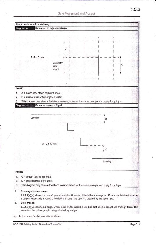
STANDARDS AND TOLERANCES GUIDE

INTRODUCTION
1.1   Authority of the Guide
The standards and tolerances identified in the      The tolerances and standards identified in the
Guide are only applicable to “building work”        Guide are applicable to new work and new
as defined in the Queensland Building and           materials and are only relevant and applicable
Construction Commission Act 1991 (QBCC Act)         within the time periods specified in Section 1.2 of
and Queensland Building and Construction            the Guide. Accordingly, unless noted otherwise,
Commission Regulation 2018. Accordingly,            they are not applicable to second‑hand or
tolerances and standards have not been included     recycled materials or products.
for constructions such as earthworks, electrical
                                                    This document has primarily been drafted to
work, carpet, vinyl or floating floors that are
                                                    enable builders, contractors and home owners
excluded from the definition of “building work”
                                                    to reference general building standards related
provided in the above mentioned legislation.
                                                    to domestic construction and hopefully to
Building standards are in the main described in     minimise the likelihood of disputes in relation
the National Construction Code Series which         to the quality of building work occurring.
includes the Building Code of Australia (BCA)
                                                    Inevitably however, some disputes in relation to
(Volumes 1 and 2) and the Plumbing Code of
                                                    quality of work will occur and in many instances
Australia (Volume 3), which is adopted into law
                                                    will be referred to the Queensland Building
by regulation.
                                                    and Construction Commission for assessment
The standards and tolerances documented in          and determination.
the Guide are intended to be consistent with and
                                                    In making its determination and in particular
complement other relevant Acts, Regulations,
                                                    when deciding whether or not to issue
BCA requirements, Australian Standards and
                                                    a Direction to Rectify to a person, the
manufacturer’s installation requirements. Where
                                                    Commission is required by Section 72 of the
there is any difference or contradiction between
                                                    QBCC Act to take into consideration all the
the Guide and an Act, Regulations, the BCA,
                                                    circumstances it considers are reasonably
Australian Standards, manufacturer’s installation
                                                    relevant. Accordingly, although the Commission
requirements; all of these take precedence
                                                    will consider the provisions of the Building
over the Guide. Where the contract may be
                                                    Act, the BCA, applicable standards and
inconsistent with the requirements of the Guide
                                                    manufacturer’s installation instructions when
the contract takes precedence only to the extent
                                                    making its determination it is not required
that it is requiring a higher standard than that
                                                    to give a Direction if it is satisfied that, in the
prescribed in the Guide.
                                                    circumstances, it would be unfair to the person
The Guide has predominately been prepared           to give the Direction.
to identify general standards and tolerances
applicable to domestic building work, however
where relevant, can similarly be applied to
non-domestic constructions. Accordingly, unless
noted otherwise, references in the Guide to
the BCA refer to Volume 2 of the BCA which is
applicable to Class 1 and 10 buildings.

6
QUEENSLAND | MAY 2019
7STANDARDS AND TOLERANCES GUIDE
1.2 Time provisions and limitations 1.3 Measurement of tolerances
The tolerances in the Guide apply up to
This edition of the Guide is valid from
and including the length over which each
1 May 2019 and has been compiled based upon
tolerance is stated to apply. It is not intended
the 2019 edition of the BCA and its referenced
that tolerances will be interpolated or
standards and other non-referenced Australian
proportioned to the actual length of building
Standards and documents in force as at
element measured. For example, where the
1 May 2019. Guide specifies a 4mm maximum deviation
measured over a 2m length of wall surface,
Two time periods are relevant when identifying the Guide means that the same 4mm deviation
applicable standards and tolerances to identify is to be applied over a 1m wall surface or a
defective work: 500mm wall surface. The tolerance cannot be
• 12 months from date of completion interpolated to mean a 2mm deviation over
of the work; a 1m wall surface or 1mm deviation over a
• 6 years and 6 months from date 500mm wall surface. Similarly, deviations
of completion of the work. over longer wall surfaces would be defects if
the deviation exceeded 4mm within any 2m
Generally the 12 month time frame applies to length of that surface.
non-structural building work and the 6 years and
6 month time frame to structural building work. Horizontal, vertical and diagonal surface
tolerances are to be interpreted in the same way.
Generally, the date of completion is the day
Horizontal surfaces
when the work carried out under the contract
is completed in accordance with the terms of Deviations from a horizontal surface are to
that contract, or the day the building owner is be measured from a datum nominated in
given the statutory permit or certificate that the contract documents or inferred, if none
authorises the occupation of the building. is nominated. Where there is a nominated or
Alternatively, a definition may be given in the inferred datum, the maximum deviation from
contract associated with the building work. that datum will not exceed the deviation stated
in the Guide. Where no datum is nominated and
Unless noted otherwise all standards and a datum cannot be inferred, a datum level will
tolerances provided in the Guide are applicable be taken to be at the highest or lowest points
for 6 years and 6 months from the date of in the building element, room or area being
completion of the work. measured. Refer to Figure 1.3 A (i), (ii) and (iii)
for method of measurement.
Vertical surfaces
Deviations of a vertical surface from a true
vertical plane are to be measured from a
plumb line through a plan position or reference
point nominated in the contract documents or
inferred, if none is nominated. The maximum
deviation of a vertical surface from that plumb
line will not exceed the deviation stated in the
Guide. Refer to Figure 1.3 B (iv), (v) and (vi) for
method of measurement.
8QUEENSLAND | MAY 2019
FIGURE 1.3A HORIZONTAL SURFACE TOLERANCES
i) MEASUREMENT OF DEVIATION FROM HORIZONTAL/LEVEL
Spirit level Maximum deviation
Horizontal level line
Surface being tested Maximum deviation
i) MEASUREMENT OF DEVIATION FROM HORIZONTAL/LEVEL
ii)Spirit level
MEASUREMENT OF BOW Maximum deviation
iii) MEASUREMENT OF BOW (HORIZONTAL FLATNESS)
Horizontal level line
Straight edge Straight edge
Maximum deviationMaximum deviation Maximum deviation
Surface being tested
ii) MEASUREMENT
Surface being tested OF BOW Maximum deviation iii) MEASUREMENTSurface
OF BOW (HORIZONTAL
being tested FLATNESS)Maximum
Equal height deviation
Straight edge packing
Straight to
edge Maximum deviation
Maximum deviation
both ends
Surface being tested Maximum deviation Surface being tested Maximum
Equal height deviation
iv) MEASUREMENT OF DEVIATION v) MEASUREMENT OF BOW vi) MEASUREMENT OF BOW
packing to
FROM VERTICAL PLUMB (SURFACE FLATNESS)
both ends (SURFACE FLATNESS)
FIGURE 1.3B VERTICAL SURFACE TOLERANCES
plumb line
plumb line
plumb line
Vertical
Vertical
Vertical
iv) MEASUREMENT OF DEVIATION v) MEASUREMENT OF BOW vi) MEASUREMENT OF BOW
FROM VERTICAL PLUMB (SURFACE FLATNESS) (SURFACE FLATNESS)
Maximum Maximum
plumb line
plumb line
plumb line
deviation deviation
Vertical
Vertical
Vertical
Maximum Maximum
Spirit level deviation deviation
Surface
Maximum Maximum Surface
deviation
Being tested deviation being tested
Straight edge
Maximum Maximum
Spirit level deviation deviation
Surface Surface
Being tested being tested
Straight edge Equal HT
Spacers
Straight edge
Maximum Maximum To be centred
deviation deviation over bow
Equal HT
Spacers
Straight edge
Maximum Maximum To be centred
deviation deviation over bow
Base of wall Base of wall Base of wall
Base of wall Base of wall Base of wall
9STANDARDS AND TOLERANCES GUIDE
1.4 Viewing and inspecting distances Slight variations in the colour and finish of
materials do not constitute a defect.
Generally, variations in the surface colour, texture
and finish of walls, ceilings, floors and roofs,
and variations in glass and similar transparent 1.5 Responsibility to rectify
materials are to be viewed where possible from Contractors do not have to rectify damage
a normal viewing position. A normal viewing caused by the owner’s actions or inactions or
position is looking from a distance of 1.5m or those of other people engaged by the owner.
greater (600mm for appliances and fixtures
and 3m for glass) with the surface or material Contractors will be liable to repair any
being illuminated by “non-critical light”. “Non- consequential damage caused by, or as a
critical light” means the light that strikes the consequence of carrying out building work
surface is diffused and is not glancing or parallel on a residential building site or to a residential
to that surface. building on an adjacent site.
FIGURE 1.4 NORMAL VIEWING POSITIONS
Ceiling
150
Wall 0m
m
1500mm
m
0m
60
m
0m
150
Floor
Viewing fixtures and appliances
Glass
3000mm
10QUEENSLAND | MAY 2019
Contractors will be liable to repair 1.6 References used in the Guide
damage caused to property in the course of
completing their building work. Building Code of Australia (BCA) 2019 Edition –
Volume 2.
For example:
The digital NCC Volume 2 can be accessed for
A contractor will not have to repaint a poorly from the ABCB at www.abcb.gov.au
painted wall that was painted by the building
owner.
A contractor will not have to repair a distorted
gutter when the damage was caused by an
owner placing a ladder against the gutter.
A contractor will not have to repair a storm
water drain that was properly constructed and
later blocked by tree roots.
A contractor will have to replace untreated pine
in an external deck that was installed by the
contractor instead of the durable timber required
for this structure.
A contractor will have to repair an existing
window in a house that the contractor
accidentally damaged when constructing
another part of the house.
A contractor will have to provide a remedy or
repair an adjoining residential building suffering
from subsidence caused by the lack of shoring
or an effective ground retention system on
a deep excavation constructed along the
property boundary.
11STANDARDS AND TOLERANCES GUIDE
2. SITEWORKS
2.1 Cracking in concrete paving
Cracking in concrete is common and is Within the first 12 months from completion of
not always attributable to unsatisfactory the work, cracking or movement in concrete
workmanship. Common causes of cracking verandahs, garages, carports, paving, patios,
include shrinkage stress, stress due to driveways etc., where the builder did not make
trees, commercial or heavy vehicle traffic, allowances for shrinkage or general movement
soil movement due to changes in the of the concrete (e.g. isolation joints where
moisture content due to garden watering or required around penetrations such as verandah
drainage problems. posts, pipes, expansion joints, control joints
and contraction joints), shall be assessed in
Cracking not attributable to the workmanship
accordance with Table 2.1 and is defective where
of the builder (e.g. trees planted too close to
the limits in that table are exceeded.
paving, commercial or heavy duty vehicle traffic,
excessive garden watering, etc.) is not a defect.
TABLE 2.1 ACCEPTANCE CRITERIA
CONDITION MEASURE LIMIT
Random cracking Crack width ≤ 1mm
Design profile Variation between actual surface profile and design profiles ≤ 15mm
Flatness Maximum deviation from a 3m straight edge (see Note 1) ≤ 15mm
Relative surface level of adjacent paving elements within the
Stepping ≤ 5mm
expanse of the main pavement (See Note 2 below)
Subsidence Offset under 1.5m length of the design profile (see Note 3) ≤ 5mm
Based on AS 3727 Part 1: Residential Table 2.2 Acceptance Criteria1.
Notes to table 2.1
1. The flatness condition shall apply only to that part of a pavement in which its surface has been intended to be
designed in the one plane, and that plane is greater than 3m in diameter.
2.The stepping criteria apply only to steps within the surface of the main pavement. It shall not apply where the main
pavement abuts other structures such as edging, drainage pits, service pits, minor pavements (such as a pathway
adjacent to a driveway) and pavements constructed with materials of a different type.
3. The design profile shall be centred over the defect and supported at its ends by equal height spacers. The change in
offset shall be then measured relative to this design profile.
1
Reproduced with permission from SAI Global Ltd under licence 1902-c082.
12QUEENSLAND | MAY 2019
Within 6 years and 6 months from completion
of the work, cracking in concrete verandahs,
garages, carports, paving, patios, driveways etc.
where the builder did not make allowances for
shrinkage or general movement of the concrete,
e.g. isolation joints where required around
penetrations such as verandah posts, pipes,
expansion joints, control joints and construction
joints, shall be assessed in accordance with Table
2.1 and is defective where the limits in that table
are exceeded and the defect constitutes a health
and safety issue such as a trip hazard or renders
the paving structurally unsound.
2.2 Finish to external concrete paving
Concrete paving finish is defective if, within
12 months from date of completion of the work,
it is not consistent in colour, texture and general
appearance. Minor variations in finish may occur
and are not considered to be defective.
2.3 Site Drainage
Surface water is required to be directed away
from the building and shaped to prevent
ponding of water near or against the footings.
Part 3.1.3.3 of the BCA provides minimum surface
water drainage requirements. In Queensland
AS 2870 Residential Slabs and Footings is widely
used as an acceptable construction manual.
Site drainage requirements must comply
with the AS 2870 provisions and any relevant
engineer design.
Site drainage will be defective if it is not in
accordance with the above requirements.
2.4 Ground clearance for driveways
The ground clearance for driveways
and the like shall be in accordance with
AS/NZS 2890.1 2004 Parking Facilities -
Off Street Parking Appendix C. The template
car is to be B85 for domestic properties.
13STANDARDS AND TOLERANCES GUIDE
3. FOOTINGS, SLABS AND SET OUT
3.1 Foundation and site drainage – Slab and footing failures are defects when they
maintenance after occupation are caused by foundation movements that are
the result of localised drying and wetting caused
The contractor is not responsible for foundation by such factors as the effects of trees, excessive
movements caused by activities that were not wetting or lack of site drainage when these
evident at the time of entering into the contract factors were present during construction.
or as a variation to that contract, or that are
undertaken by the owner. These include paving, Slab and footing failures are also defects
landscaping, planting trees and drainage works where they are caused by foundation
after the site is handed over to the owner. movement that is the result of inadequate
fill, or inadequate compaction of either fill or
The contractor is not responsible for foundation natural material irrespective of whether or not
movements caused by the owner’s failure to the fill may have been provided with a Level 1
maintain drainage systems after the site is Compaction Certificate.
handed over to the owner.
Refer to the Queensland Building and 3.3 Setting out the building on the site
Construction Commission publication A building set out is defective where the set out
“A Simple Guide to Preventing Structural has failed to comply with the requirements of
Damage to Your Home”. the approved drawings, the allotment Certificate
of Title, planning or development approval,
3.2 Footings and slabs generally relevant planning overlays and schemes and
building regulations.
In order for domestic footing designs to
be practical and economical to construct, Within the first 12 months from completion of
AS 2870 - Residential Slabs and Footings the work and provided the building set out has
accepts that although usually no damage complied with these regulated provisions, the
occurs during the life of the building some set out for a building is defective if the building
slight or minor damage to walls and floors due is more than 50mm from its correct position and
to footing movement is possible. This slight or such deviation adversely affects the safe use or
minor damage is not a defect. reasonable amenity of the building.
Slabs and footings are defective if they fail
because they are not designed and constructed
in accordance with the BCA and/or AS 2870 –
Residential Slabs and Footings.
14QUEENSLAND | MAY 2019
3.4 External building dimensions stairways, are defects if they exceed L/100 or
5mm, whichever is the greater, where L is the
Within the first 12 months from completion of documented dimension and such deviation
the work, departures from documented external adversely affects the safe use or reasonable
dimensions of buildings are defects if they amenity of the building.
exceed L/200 where L is the documented overall
length of wall, or 5mm, whichever is the greater Within 12 months from completion of the
and such deviation adversely affects the safe use work, departures from documented set out for
or reasonable amenity of the building. external elements such as garages, carports,
verandahs, decks, patios etc. are defects if they
exceed L/100 or 5mm, whichever is the greater,
3.5 Measuring internal
where L is the documented dimension and
building dimensions such deviation adversely affects the safe use or
Unless shown otherwise, dimensions shown reasonable amenity of the building.
on drawings for internal walls always refer to Within 12 months from completion of the work,
the structure’s dimensions. Structure means the set out is defective where a specific fixture
masonry and timber framing and does not or feature is required to be accommodated, and
include finishes such as plasterboard, render and such documented dimensions to accommodate
skirtings. The internal room sizes will be different that fixture or feature are not provided and
when thicknesses of internal finish materials are such deviation adversely affects the safe use or
taken into account. reasonable amenity of the building.
Ceiling height dimensions are defective if they
do not comply with the requirements of the 3.7 Finished floor levels
BCA. Within the first 12 months from completion
of the work, ceiling height dimensions are Finished Floor Levels (FFL) or Reduced Levels
defective if they do not comply with any greater (RL) are defective where they do not comply
height (in excess of BCA requirements) specified with planning and building requirements, for
in the contract and such deviation adversely example minimum levels in flood prone areas.
affects the safe use or reasonable amenity of Within the first 12 months from completion
the building. of the work, Finished Floor Levels (FFL) or
Reduced Levels (RL) are defective where:
3.6 Building dimensions • they depart from the documented FFL or
Within 12 months from completion of the work, RL by more than 40mm and such deviation
departures from the documented set out for adversely affects the safe use or reasonable
service rooms such as bathrooms, toilets, amenity of the building; or
laundries, kitchens etc. are defects if they • floors that are documented to be on the
exceed L/200 or 5mm, whichever is the greater, same plane are constructed on different
where L is the documented dimension and planes and such deviation adversely affects
such deviation adversely affects the safe use the safe use or reasonable amenity of the
or reasonable amenity of the building. building; or
Within 12 months from completion of the • the building work is an extension or
work, departures from the documented set addition and new floor levels do not match
out for habitable rooms and areas, such as the existing building floor levels and such
bedrooms, dining rooms, lounge and living deviation adversely affects the safe use or
rooms, family rooms, studies, halls, entries and reasonable amenity of the building.
15STANDARDS AND TOLERANCES GUIDE
3.8 Levelness of concrete floors 3.11 Domestic concrete slabs
Except where documented otherwise, new that form part of a termite
floors are defective if within 12 months from management system
completion of the work, they differ in level by Where a domestic slab is designed in
more than 10mm in any room or area, or more accordance with the BCA and is to act as
than 12mm in any 3m length and such deviation part of a termite management system, cracks
adversely affects the safe use or reasonable through the slab are not to exceed Category 1
amenity of the building. The overall deviation width as set out in Table 3.10.
of floor level to entire building footprint shall
not exceed 20mm within 12 months from date
of completion of the work and such deviation 3.12 Finish to concrete slabs
adversely affects the safe use or reasonable Within the first 12 months from completion
amenity of the building. of the work, the finish to a concrete slab is
defective if it is not suitable for the documented
3.9 Dimensions of building elements applied finishes such as tiles, polished concrete,
Deviations from the documented height or carpet or sheet flooring, including set downs
cross-sectional dimension of building elements where required.
such as beams and posts are defective if
the deviation renders them or the building 3.13 Repairs to exposed concrete slabs
structurally inadequate.
Repairs, where failure has been due to cracking
Within the first 12 months from completion and/or movement, may involve the removal of
of the work, deviations from the documented the affected area. Within the first 12 months
height or cross-sectional dimension of building of completion of the repair work, the repair is
elements such as beams and posts are defective defective if it does not, as closely as practicable,
if they exceed L/200 where L is the documented match the existing work in appearance, colour
dimension or 5mm, whichever is the greater and and texture. Minor variations in finish are not
such deviation adversely affects the safe use or considered defective.
reasonable amenity of the building.
Notwithstanding the above, timber members Where repairs are made to a domestic slab
are not defective if the dimensional difference is designed in accordance with the BCA to act as
due to timber shrinkage provided that shrinkage part of a termite management system, any repairs
does not exceed 3% for seasoned timber and are defective, unless they ensure on completion that
10% for unseasoned timber or is the result of the termite management system is appropriately
subsequent dressing to nominated nominal re-instated in accordance with the requirements
timber dimensions. of the BCA.
3.10 Cracks in concrete slabs
Refer to Table 3.10 for descriptions of
categories of cracks. Category 3 and 4 cracks
to slabs are defects. Category 1 and 2 cracks
to slabs are not defects.
16QUEENSLAND | MAY 2019
3.14 Slab edge dampness (e.g. permits mould growth or damages floor
finishes, carpets etc.).
The performance requirements of the BCA
require, amongst other things, that buildings The work is not defective if such water
safeguard occupants from illness and injury penetration is caused by actions or inactions by
and protect buildings from damage caused the owner, or others outside of the contractor’s
by surface water, external moisture entering control including such things as landscaping
a building and the accumulation of internal that directs water towards the building or
moisture in a building. restricts the free flow of water away from the
building, excessive garden watering adjacent to
Accordingly, the waterproofing of slab and the building and the subsequent construction of
footing systems is defective if it permits surface paving adjacent to the building that compromises
water, sub-surface water and other external the ability of the water to drain away from
moisture to enter a building to the extent that it the building.
compromises the health and safety of occupants
or has the potential to damage the building or
its contents.
TABLE 3.10 CLASSIFICATION OF DAMAGE TO CONCRETE FLOORS
DESCRIPTION OF APPROX. CRACK CHANGE IN OFFSET FROM DAMAGE
TYPICAL DAMAGE WIDTH LIMIT IN 3m STRAIGHT EDGE CATEGORY
FLOOR PLACED OVER DEFECT
(SEE NOTES)
Hairline cracks, insignificant
< 0.3mm < 8mm 0 Negligible
movement of slab from level
Fine but noticeable cracks.
< 1.0mm < 10mm 1 Very Slight
Slab reasonably level
Distinct cracks. Slab noticeably
< 2.0mm < 15mm 2 Slight
curved or changed in level
Wide cracks. Obvious curvature
2mm to 4mm 15mm to 25mm 3 Moderate
or change in level
Gaps in slab. Disturbing
4mm to 10mm > 25mm 4 Severe
curvature or change in level
Extract from AS 2870 - Residential Slabs and Footings2
Notes
1. The straight edge is centred over the defect, usually, and supported at its ends by equal height spacers.
The change in offset is then measured relative to this straight edge, which is not necessarily horizontal.
2. Local deviation of slope, from the horizontal or vertical, of more than 1:100 will normally be clearly visible.
Overall deviations in excess of 1:150 are undesirable.
3. Account should be taken of the past history of damage in order to assess whether it is stable or likely to increase.
2
Reproduced with permission from SAI Global Ltd under licence 1902-c082.
17STANDARDS AND TOLERANCES GUIDE
4. MASONRY
4.1 Masonry types Tolerances for face work for aesthetic reasons
must be to the manufacturer’s requirements.
This section includes structural tolerances for
the following generally-used types of masonry,
including:
4.2 Damage to masonry walls
• clay and concrete brick construction Refer to Table 4.2 for descriptions of categories
of damage. Category 3 or greater damage to
• clay and concrete brick veneer construction
walls is a defect and requires investigation,
• concrete block construction. stabilisation, monitoring and rectification work,
The structural tolerances for the above may not which may include breaking out and replacing
always be appropriate for some types of masonry sections of the wall. Category 0, 1 and 2 cracks
construction, such as pre-fabricated masonry to walls are not defects. Category 2 damage is
panels, aerated concrete blocks, irregular cut stone, a defect if identified within 12 months from date
rustic finish masonry with irregular edges and of completion and requires minor repair work
appearance etc. In these cases, the manufacturer’s such as repointing.
requirements must be followed.
TABLE 4.2 CLASSIFICATION OF DAMAGE WITH REFERENCE TO WALLS
APPROX. CRACK
DESCRIPTION OF TYPICAL DAMAGE
WIDTH LIMIT
DAMAGE AND REQUIRED REPAIR CATEGORY
(SEE NOTE 1)
Hairline cracks < 0.1mm 0 Negligible
Fine cracks that do not need repair < 1mm 1 Very Slight
Cracks noticeable but easily filled.
< 5mm 2 Slight
Doors and windows stick slightly
5mm to 15mm
Cracks can be repaired and possibly a small amount of wall
(or a number of cracks
will need to be replaced. Doors and windows stick. Service 3 Moderate
3mm or more in one
pipes can fracture. Weather tightness often impaired
group)
Extensive repair work involving breaking-out and replacing
sections of walls, especially over doors and windows. 15mm to 25mm but also
Window and door frames distort. Walls lean or bulge depends on number of 4 Severe
noticeably, some loss of bearing in beams. cracks
Service pipes disrupted
Extract from AS 2870 - Residential Slabs and Footings3
Notes
1. W
here the cracking occurs in easily repaired plasterboard or similar clad-framed partitions, the crack width limits may be
increased by 50% for each damage category.
2. Crack width is the main factor by which damage to walls is categorised. The width may be supplemented by other
factors, including serviceability, in assessing category of damage.
3. In assessing the degree of damage, account shall be taken of the location in the building or structure where it occurs,
and also of the function of the building or structure.
3
Reproduced with permission from SAI Global Ltd under licence 1902-c082.
18QUEENSLAND | MAY 2019
4.3 Articulation in masonry walls • be sealed with a suitable flexible sealant to
match the colour of the adjacent masonry.
Masonry work is defective if articulation and
movement control joints have not been provided
as required by AS 2870, AS 3700 or the contract. 4.4 Masonry construction generally
Articulation joints are defective if they do not Within the first 12 months from completion of
comply with the following: the work, masonry work is defective if it exceeds
• be free of mortar the structural tolerances set out in Table 4.4 or
• be vertical and not toothed unless toothing the manufacturer’s aesthetic requirements.
is specifically considered in the design Within 6 years and 6 months from completion of
• extend the full height of the masonry but the work, the masonry is defective if it exceeds
may be omitted below the damp-proof the structural tolerances set out in Table 4.4 and
course (DPC) if there is not more than as a result compromises the structural adequacy
600mm of masonry below the DPC at of the wall or building, allows water penetration
the position of the joint into the building or compromises the health and
• the material used to fill the joint must be of a safety of those who use the building.
type that does not inhibit the performance of
the joint
TABLE 4.4 TOLERANCES IN MASONRY CONSTRUCTION
ITEM TOLERANCE
a. Horizontal position of any masonry element specified or
±15mm (Refer Figure 4.4 A)
shown in plan at its base or at each storey level
b. Relative displacement between loadbearing walls in adjacent
±10mm (Refer Figure 4.4 B)
storeys intended to be in vertical alignment
The lesser of ±10mm per
c. Maximum deviation from plumb within a storey from a vertical 3m of height or 0.05 times the
line through the base of the member thickness of the leaf
(Refer Figure 4.4 C)
d. Maximum deviation from plumb in the total height
±25mm (Refer Figure 4.4 D)
of the building (from the base)
e. Maximum horizontal or vertical deviation of a surface from a
±5mm (Refer Figure 1.3 A and 1.3 B
plane surface (bow)
f. Deviation of bed joint from horizontal, or from the level ±10mm in any 10m length, ±15mm
specified or shown in elevation in total (Refer Figure 4.4 E)
g. Deviation from specified thickness of bed joint ±3mm (Refer Figure 4.4 F)
h. Minimum perpend thickness 5mm
i. Deviation from specified thickness of perpend ±10mm max
j. Deviation from specified width of cavity ±15mm (Refer Figure 4.4 G)
Extract from AS 3700 - Masonry Structures 4
4
Reproduced with permission from SAI Global Ltd under licence 1902-c082.
19STANDARDS AND TOLERANCES GUIDE
4.5 Durability requirements for 4.8 Masonry facing
masonry and built-in components Within the first 12 months from completion of
Masonry and/or built-in components are the work, and unless documented otherwise,
defective if they do not satisfy the durability masonry is defective if it is not laid with true,
requirements for the relevant exposure fair or finish face outwards.
environments as required by AS 3700 Within the first 12 months from completion of
Masonry Structures. the work and unless documented otherwise,
masonry faces are defective if they are not
4.6 Blending and matching cleaned and free of excess mortar or stains
of masonry – repair work when viewed from the normal viewing position.
If matching masonry in alteration and repair
work is not reasonably possible, contractors 4.9 Mortar for masonry
should use a practical approach and, where Within the first 12 months from completion
possible, a physical joint, a door, a window, of the work, mortar is defective if it is not in
a downpipe or similar separator should be accordance with the requirements of the
incorporated to lessen the impact of the new AS 3700 Masonry Structures and AS 4773
work. In the case of alteration and repair work Masonry for Small Buildings Parts 1 and 2.
however, failure to match the original masonry
units is not considered a defect. Within 6 years and 6 months from completion
of the work, mortar for masonry is defective if
Mortar repairs should be carried out to it is not in accordance with the requirements of
match existing mortar as closely as practicable. the AS 3700 Masonry Structures and AS 4773
A perfect colour match may not be possible Masonry for Small Buildings Parts 1 and 2 and as
and differences may diminish over time. a result compromises the structural adequacy
Some variation of masonry features such as of the wall or building, allows water penetration
colour, texture and pattern are to be expected into the building or compromises the health and
between batches and are not considered safety of those who use the building.
a defect.
4.10 Voids and holes in mortar
4.7 Blending and matching
Within the first 12 months from completion of the
of masonry – new work
work, voids and holes in mortar in masonry walls,
To avoid inconsistency in appearance, wherever excepting weepholes and vents, are defects if
practicable, masonry units for buildings should they are visible from a normal viewing position.
be obtained from the same batch.
During the first 12 months from completion
of the work, masonry areas that vary in
colour are defective if the units are not mixed
and/or distributed in accordance with the
manufacturer’s installation instructions or
do not reasonably match masonry in display
panels and display homes.
20QUEENSLAND | MAY 2019
FIGURE 4.4 TOLERANCES IN MASONRY CONSTRUCTION
DIAGRAM
DIAGRAM
A A DIAGRAM
DIAGRAM
B B
VERTICAL PLUMB LINE
VERTICAL PLUMB LINE
15mm 15mm
maximummaximum
deviation
deviation
from specified
from specified
or documented
or documented
dimension
dimension
VERTICAL PLUMB LINE
VERTICAL PLUMB LINE
FLOORFLOOR
LEVELLEVEL
CEILING
CEILING
LEVELLEVEL 10mm 10mm
maximum
maximum
deviation
deviation
relative
relative
displacement
displacement
between
between
load bearing
load bearing
walls walls
GROUND
GROUND
LEVEL LEVEL
VERTICAL PLUMB LINE
VERTICAL PLUMB LINE
DIAGRAM
DIAGRAM
C C DIAGRAM
DIAGRAM
D D
VERTICAL PLUMB LINE
VERTICAL PLUMB LINE
25mm25mm
maximum
maximum
10 mm10 mm
deviation
deviation
maximum
maximum
deviation
deviation
TOP
TOP OF OF WALL
WALL
CEILING LEVELLEVEL
CEILING CL CL
H Storey
H Storey
heightheight
withinwithin
any storey
any storey
BASE MEMBER
BASE MEMBER
FLOORFLOOR
LEVELLEVEL
FLOORFLOOR
LEVELLEVEL FL FL
CEILING
CEILING LEVELLEVEL
GROUND
GROUND
LEVELLEVEL
Building
Building
may be may be H H
a single
a single
or several
or several Total height
Total height
of of
storeysstoreys
high high masonary
masonary
wall wall
VERTICAL
VERTICAL
SECTION
SECTION
THROUGH
THROUGH
WALLWALL FLOORFLOOR
LEVELLEVEL
T T Thickness
Thickness
of leafof leaf
CEILING
CEILING LEVELLEVEL
FORMULA:
FORMULA:
Maximum
Maximum
deviation
deviation
from plumb
from plumb
withinwithin
any storey
any storey
STRUCTURAL
STRUCTURAL
LESSER LESSER
OF OF
( ( (
10H 10H
3 3
OR 0.05T
OR 0.05T
FLOORFLOOR
LEVELLEVEL
BASE OF
BASE OF
MEMBER
MEMBER
H measured in metres
H measured (m) (m)
in metres
T measured in millimetres
T measured (mm) (mm)
in millimetres
GROUND
GROUND LEVELLEVEL GL GL
For example if a storey
For example height,height,
if a storey h=4000mm and leaf
h=4000mm andthickness, t=190mm.
leaf thickness, t=190mm.
Tolerance is lesser
Tolerance of 10 xof
is lesser 4.0
10÷x34.0
= 13.3mm or 0.05orx0.05
÷ 3 = 13.3mm 190 =x 9.5mm
190 = 9.5mm
ie. 9.5mm
ie. 9.5mm
21STANDARDS AND TOLERANCES GUIDE
FIGURE 4.4 TOLERANCES IN MASONRY CONSTRUCTION CONTINUED.
Spirit level
DIAGRAM E 15mm maximum in total
HORIZONTAL LEVEL LINE
Surface
being tested
10mm maximum deviation of bed joint
from horizontal in any 10m length of wall
DIAGRAM F Maximum or
documented
13mm thickness +3mm
Nominal thickness
10mm of bed joint or
as documented
7mm Maximum or
documented
thickness -3mm
GROUND LEVEL
DIAGRAM G Documented position Documented position
of brickwork of brickwork
15mm maximum 15mm maximum
deviation from deviation from
width of cavity width of cavity
Timber stud wall Timber stud wall
Documented Documented
width of cavity width of cavity
CONCRETE SLAB CONCRETE SLAB
NOTE: REFER BCA FOR MINIMUM CAVITY WIDTH
22QUEENSLAND | MAY 2019
4.11 Cracked masonry unit 4.14 Vertical alignment of perpend joints
It is characteristic of some masonry units to Within the first 12 months from completion
have surface cracks or crazing as part of the of the work, a line of masonry perpends is
manufacturing process. These are not defects defective if it exceeds a maximum deviation
unless they occur within the first 12 months of from vertical alignment of 15mm per 2m height
completion of the work and they result in the of wall, measured from centre to centre of
complete fracture of the unit. perpend joints.
4.12 Cleaning, mortar smears and stains 4.15 Horizontal alignment of bed joints
Within the first 12 months from completion of Within the first 12 months from completion of
the work, stains, mortar smears and damage the work, bed joints in walls including adjacent
caused by cleaning are defects if they are visible isolated piers and either side of openings and
from a normal viewing position. control joints are defective if they are not on the
same horizontal plane, or do not comply with
4.13 Masonry inside garages and similar Table 4.4 of this Guide.
spaces and under applied finishes
4.16 Base bed joint and base row
Within the first 12 months from completion
of masonry
of the work, structural masonry that is visible
inside a garage or similar space or through an Within the first 12 months from completion of
applied finish is defective if it does not comply the work, exposed base bed joints above the
with the tolerances in Table 4.4, however, these finished ground level are defective if they exceed
tolerances do not apply to the non-face side of 20mm in thickness. Base bed joints that are
single skin masonry. not exposed above the finished ground level
are defective if they are greater than 40mm
Within 6 years and 6 months from completion
in thickness. Split masonry units and units on
of the work, structural and non-structural
edge used in the base row of units are defective
masonry is defective if it exceeds the tolerances
if they are exposed.
set out in Table 4.4 and as a result compromises
the structural adequacy of the wall or building, Within 6 years and 6 months from completion
allows water penetration into the building or of the work, the base bed joint and base row
compromises the health and safety of those of masonry is defective if it exceeds 40mm
who use the building. in thickness and as a result compromises the
structural adequacy of the wall or building,
When there is an applied finish such as render,
allows water penetration into the building or
where the joints are not intended to be visible,
compromises the health and safety of those
masonry need not be saw cut and 1/4 or 3/4
who use the building.
units may be used in lieu of full masonry units.
23STANDARDS AND TOLERANCES GUIDE
4.17 Masonry that overhangs If unseasoned hardwood timber is used,
concrete slabs clearances must be increased from these
minimums to suit the particular timber
Within the first 12 months from completion of species used.
the work, the installation of a masonry course is
defective if it is laid on a concrete slab or strip
4.21 Sealing of masonry
footing so as to project over the edge of the slab
or footing by more than 15mm. Refer to Figure articulation joints
5.11 in this Guide. Articulation joints in masonry veneer, single skin
Within 6 years and 6 months from completion masonry or double skin masonry, are defective if
of the work, masonry that overhangs concrete they have not been sealed.
slabs is defective if it projects over the edge of Within the first 12 months from completion of
the slab or footing by more than 15mm and as the work and unless documented otherwise,
a result compromises the structural adequacy flexible mastic or sealant is defective if it does
of the wall or building, allows water penetration not match as close as practicable the colour
into the building or compromises the health of the adjacent surface, and has not been
and safety of those who use the building. used in accordance with the manufacturer’s
installation instructions.
4.18 Damp proof courses
Damp proof courses are defective if they are
not installed in accordance with the BCA and
AS 3700 Masonry Structures and AS 4773 FIGURE 4.20 SHRINKAGE ALLOWANCE
Masonry for Small Buildings Parts 1 and 2. FOR TIMBER FRAMING
4.19 Raking of joints
Within the first 12 months from completion of
the work and where documented, mortar joints
in masonry units are defective if they are raked
out to a depth of more than 10mm or are not
consistent in depth throughout.
12mm
4.20 Brick sills, sill tiles and shrinkage
allowance for timber framing
Quad mould
In masonry veneer walls a gap must be left
between the timber frame and the top of the
masonry wall, window sills etc., to allow for
initial settlement of the timber framing caused
by timber shrinkage. Refer to Figure 4.20 in
this Guide.
Work that does not provide the following 10mm
clearances and causes damage within the first
12 months from completion of construction
is defective:
• 10mm at sills of windows; and
• 12mm at roof overhangs.
24QUEENSLAND | MAY 2019
5. FRAMING
5.1 Verticality or plumbness 5.2 Verticality or plumbness of timber
of stumps or piles frames and exposed posts
Within the first 12 months from completion of Within the first 12 months from completion of
the work, stumps or piles are defective if they the work, posts and wall frames are defective if
deviate from vertical by more than 10mm in they deviate from vertical by more than 4mm
the first 1m or more than 20mm in total length, within any 2m height. Refer to Figure 1.3 B in this
measured from ground level. Refer to Figure 5.1 Guide for method of measurement.
in this Guide.
Within 6 years and 6 months from completion
Within 6 years and 6 months from the of the work, posts and wall frames are defective
completion of the work, stumps and piles are if they deviate from vertical by more than
defective if they deviate from vertical by more 4mm within any 2m height and as a result
than 10mm in the first 1m or more than 20mm in compromises the structural adequacy of the wall
total length, measured from the ground and as or building, allows water penetration into the
a result compromises the structural adequacy building or compromises the health and safety
of the stumps or piles, allows water penetration of those who use the building.
into the building, or compromises the health and
safety of those who use the building. 5.3 Straightness of timber
frame surfaces
FIGURE 5.1 VERTICALITY OF STUMPS,
Within the first 12 months from completion of
POSTS OR PILES
the work, frames are defective if they deviate
from plane (horizontal or vertical bow) by more
Vertical plumb line
than 4mm in any 2m length of wall. Refer to
Figure 1.3 A and B in this Guide for method of
measurement.
Frames that will be subject to the subsequent
20mm fixing of plasterboard must be such that when a
maximum 1.8m straight edge is placed over the wall frame
deviation the maximum deviation from the straight edge
overall
must not exceed 4mm over 90% of the area and
not exceed 5mm over the remaining area.
Spirit level Within the first 12 months from completion of
10mm
the work, frames that exceed these tolerances
maximum are defective. Refer Figure 5.3 which reproduces
deviation Table 5.2.2 from AS 2589.
in first
1000mm
1000 mm
Ground level
25STANDARDS AND TOLERANCES GUIDE
FIGURE 5.3 DEVIATION IN THE POSITION OF THE BEARING SURFACE OF THE FINISHED
FRAMING CLASSIFICATION OF DAMAGE WITH REFERENCE TO WALLS
LEVELS 3 AND 4 LEVEL 5
SUBSTRATE TYPE DEVIATION OF DEVIATION OF DEVIATION OF DEVIATION OF
90% OF AREA REMAINING 90% OF AREA REMAINING
(MM) AREA (MM) (MM) AREA (MM)
Steel and timber framing
4 5 3 4
and battened masonry
1.8m straight edge
1.8m straight edge
Deviation from plane in arrow direction
shall not exceed the tolerances in
table above
1.8m straight edge
Extract from AS2589 - Gypsum lining: Application and finishings5
5
Reproduced with permission from SAI Global Ltd under licence 1902-c082.
5.4 Steel wall frames Within the first 12 months from completion of
the work, walls that are specified as straight are
Steel wall framing is defective if it does not comply defective if they deviate by more than 5mm over
with the BCA and one of the following: AS 4100 a 3 metre wall length and where wall panels join
– Steel structures, AS/NZS 4600 – Cold Formed to form a continuous wall, the critical face or
Steel Structures, or NASH – Residential and Low- faces of the panel are defective if they deviate by
rise Steel Framing – Part 1 Design Criteria. more than 2mm at the joint.
26QUEENSLAND | MAY 2019
Within the first 12 months from completion 5.7 Timber shrinkage
of the work, frames that will be subject to the
subsequent fixing of linings must be such that Within the first 12 months from completion of
when a 1.8m straight edge is placed over the the work, timber is defective if it has shrunk
wall frame the maximum deviation from the more than 10% if it is unseasoned or 3% if it
straight edge must not exceed 3mm over is seasoned.
90% of the area and not exceed 4mm over Within 6 years and 6 months from the
the remaining area. Frames that exceed these completion of the work, timber is defective if it
tolerances are defective. has shrunk more than 10% if it is unseasoned and
Within the first 12 months from completion of 3% if it is seasoned and as a result compromises
the work, walls must not deviate from vertical the structural adequacy of the timber, allows
by more than H/600 where H is the height of the water penetration into the building, or
wall, or 3mm, whichever is the greater. Walls that compromises the health and safety of those
exceed these tolerances are defective. who use the building.
Within the first 12 months from completion
5.8 Fixing timber stud walls
of the work, loadbearing structural walls are
defective if the gaps between the bottom plate to concrete slabs
and concrete slab are greater than 3mm and are Fixing of timber bottom plates is defective if
not packed at each stud with load bearing shims it does not comply with the BCA, AS 1684 –
or grout. Non-loadbearing walls are defective Residential Timber-framed Construction and the
if gaps between the bottom plate and concrete fixing manufacturer’s installation requirements.
slab exceed 3 mm and the gaps are not filled at
each jamb stud and at points where fixed to the
slab with load bearing shims or grout.
5.9 Fixing metal stud walls
to concrete slabs
Within 6 years and 6 months from completion
of the work, the wall frames are defective if they Fixing of metal bottom plates is defective if it
compromise the structural adequacy of the wall does not comply with the BCA and the fixing
or building, allow water penetration into the manufacturer’s installation requirements.
building or compromise the health and safety of
those who use the building. 5.10 Treads and risers in stairs
Stairs are defective if they do not comply with
5.5 Packing under timber bearers the requirements of the BCA. The top and
Packing to stumps or piers under bearers is bottom risers may be varied to allow for the
defective if it is not made of durable, non- installation of the approved documented floor
compressible materials, such as engineered finishes, to provide uniform and constant riser
plastic packers, or does not provide the height throughout after the installation of the
minimum bearing area required by the AS 1684 approved floor finishes.
– Residential Timber-framed Construction, or is Stairs must be built with constant goings and
more than a total thickness of 20mm or is not risers except as permitted by the variations
fixed in a workman-like manner. stated within the National Construction Code.
The variations are intended to account for
5.6 Attachment of joist, bearers and
conditions such as movement of materials due
trusses to steel wall frames to atmospheric moisture changes or minor
Attachment of floor joists, bearers, trusses and deviations in materials.
rafters to walls is defective if the gap between The finished going and riser dimensions
these members and the wall exceeds 3mm and however must not exceed the limitations for
the gap is not packed with load bearing shims. the maximum and minimum dimensions as
stated in the code.
27STANDARDS AND TOLERANCES GUIDE
FIGURE 5.10 MINOR DEVIATIONS IN A STAIRWAY
Diagram a. Diagram b.
Deviation in adjacent risers Deviations over a flight
Landing
C
B
A - B ≤ 5mm
Nominated
riser A
C - D ≤ 10mm
height
D
Landing
Notes: Notes:
1. A = larger riser of two adjacent risers. 1. C = largest riser of the flight.
2. B = smaller riser of two adjacent risers. 2. D = smallest riser of the flight.
3. This diagram only shows deviations in risers, 3. This diagram only shows deviations in risers, however
however the same principle can apply for goings. the same principle can apply for goings.
The allowable tolerances have two concurrent 5.11 Bottom plates that overhang
requirements: concrete slabs
• adjacent risers or adjacent goings must be Bottom plates that are at least 90mm wide
within 5mm of each other; and and overhang concrete slabs by in excess of
• the largest and smallest riser, or the largest 15mm are defective and bottom plates that
and smallest going within a flight must be are 70mm wide and overhang slabs by in
within 10mm of each other. excess of 10mm are defective, refer to
figure 5.11. In each instance, these permissible
These tolerances shall not be applied to overhangs, are subject to the minimum edge
allow for poor construction practice. distance for both the bottom plate and the
concrete slab fixing locations being satisfied
and minimum cavity widths as required by the
BCA also being maintained.
5.12 Timber durability
Timber used for structural purposes is defective
if it does not have adequate durability for its
relevant exposure conditions as defined in the
BCA and Queensland Government, Department
of Agriculture, Fisheries and Forestry -
Construction Timbers in Queensland.
28QUEENSLAND | MAY 2019
FIGURE 5.11
BOTTOM PLATES THAT OVERHANG
CONCRETE SLABS
Stud
Documented
width of cavity
Fastener’s
minimum edge
distance from Masonry
edge of the wall skin
bottom plate
15mm
Concrete slab
maximum
brick
overhang
as per
BCA
10mm maximum
Fastener’s minimum for 70mm studs
edge distance from
concrete edge 15mm maximum
requirements for 90mm studs
29STANDARDS AND TOLERANCES GUIDE 6. WALL CLADDING 6.1 Leaks in wall cladding Completed wall cladding and accessories are defective if they leak under weather conditions anticipated by the BCA. 6.2 Wall cladding Within the first 12 months of completion of the work, staining, folds, splits, dents, open joints between panels, cracking and other distortions in wall cladding, are defects if they are visible from a normal viewing position at ground level or an upper floor level. Within 6 years and 6 months from completion of the work, the wall cladding is defective if it compromises the structural adequacy of the wall or building, allows water penetration into the building or compromises the health and safety of those who use the building. 30
QUEENSLAND | MAY 2019

7. ROOFING
7.1 Flashings and accessories Where a membrane system is used on parapet
walls these systems are defective if they are
Completed flashings and accessories are not installed in accordance with AS 4654 –
defective if they leak under weather conditions Waterproofing Membranes for External Above-
anticipated by the BCA. ground Use.
Inadequate construction of roof flashings such
as cavity flashings, stepped flashings, parapet 7.2 Leaks in roofing
flashings, apron flashings and hip and valley
Roofing and accessories are defective if they
flashings are a major cause of leaking roofs.
leak under weather conditions anticipated by
Some recommended flashings details sourced the BCA.
from the BCA, AS Handbook HB39 2015 –
Installation Code for Metal Roofing and Wall
Cladding and manufacturer’s installation
recommendations, are provided in Figure 7.1.
FIGURE 7.1A PARAPET FLASHING (SOURCE HB39)
Parapet capping
Fall 3° minimum
Drip edge wide Attachment by cleats or some
enough to clear other means to permit thermal
fascia material movement (see detail below)
Capping
Parapet wall
Cleat
Extract from AS Handbook HB39 - 2015 - Installation Code for Metal Roofing and Wall Cladding6
6
Reproduced with permission from SAI Global Ltd under licence 1902-c082.
31STANDARDS AND TOLERANCES GUIDE
FIGURE 7.1B PARAPET FLASHING SET INTO BRICKWORK OR ROOF TO WALL FLASHING
(SOURCE BCA)
75mm
minimum
Anticapillary break
FIGURE 7.1C STEPPED CAVITY FLASHING
Over flashing
Weep hole
75mm lap
Weep hole
75mm apron flashing turned
up behind overflashing
32QUEENSLAND | MAY 2019
FIGURE 7.1D APRON/COVER FLASHING
COVER FLASHING
MASONRY DETAIL A
Mortar Wedge
and sealant
See detail A x
x
x
xx
x
Apron/cover
flashings
22mm (min)
10mm / 30º
FIGURE 7.1E SKILLION PATIO ROOF EXTENSION TO EXISTING DWELLING
Cover flashing plus 75mm apron
flashing turned up behind
33STANDARDS AND TOLERANCES GUIDE
FIGURE 7.1F ANTI-CAPILLARY BREAKS
FACIA FLASHING BRICK PARAPET COVER FLASHING
3°
90° Facia
10 mm 30°
10 mm
RETURN TO SUIT PROFILE DEPTH
34You can also read