Landmark 365 User Guide - Heartland Owners Manuals
←
→
Page content transcription
If your browser does not render page correctly, please read the page content below
Heartland Owners Forum                       http://manuals.heartlandowners.org

Landmark 365 User Guide

Landmark 365 User Guide V1.1.pdf   Page |1          Version 1.1, March 10, 2016

Heartland Owners Forum http://manuals.heartlandowners.org
Landmark 365 User Guide
This guide is intended to assist Heartland Landmark 365 owners by augmenting the information
found in the Heartland Landmark Manual.
Note that as model years change, Heartland introduces changes to the product. Changes may also
be made mid-year. As a result, it’s impossible to stay up-to-date for very long in a document like
this. Nevertheless, the information here may prove helpful to you. Check the date of the
document in the footnote. If the document is more than 1 year old, some information may be
dated.
Important Notices
Who created this document?
This document has been created by Heartland Owners independently of the
Heartland RV Company, and is posted to the Heartland Owners Forum, by
owners, as a service to the entire owner community.
Errors and Omissions
Because the authors are Heartland owners, not engineers or service technicians,
it’s possible that this document could contain errors or omissions. Readers are
advised to also review the manufacturers’ product documentation for more
complete information and guidance.
Additional Resources
The heartlandowners.org website has a collection of owner-written user guides,
including information on water systems, heating and cooling, winterizing,
residential refrigerator, water heater and other topics. This information is
available at http://manuals.heartlandowners.org/?man=User%20Guides
Limitations on Using this Document
This document may not be modified or sold.
It may not be posted on the internet without permission.
Other websites may link to the page from which the document may be
downloaded, but may not link directly to the document without
permission (search engines excluded).
Contact Information
Questions and comments may be directed to manuals@heartlandowners.org
Landmark 365 User Guide V1.1.pdf Page |2 Version 1.1, March 10, 2016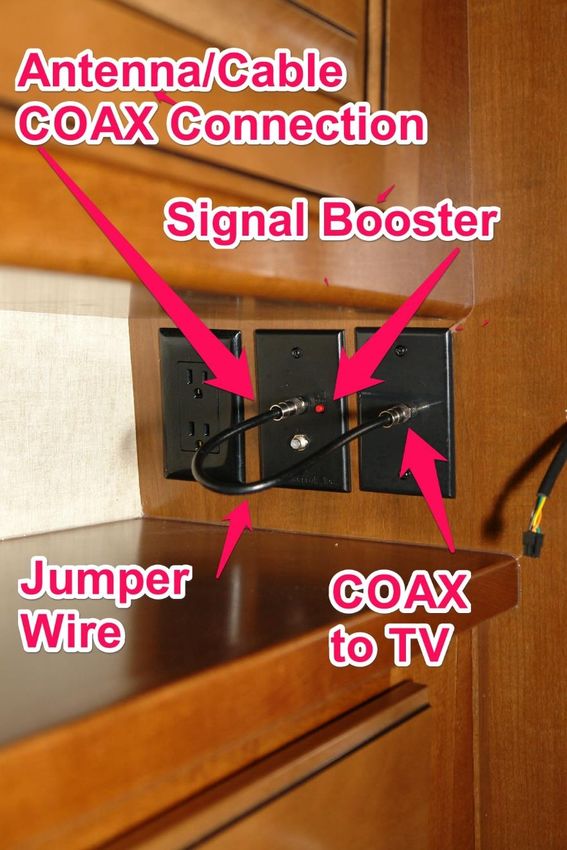
Heartland Owners Forum                                                                                  http://manuals.heartlandowners.org

Landmark 365 User Guide
Table of Contents
Landmark Evolution to the Landmark Three Sixty Five ................................................................................ 7
Introduction to Landmark 365 Features ....................................................................................................... 7
Control Panel................................................................................................................................................. 7
   Slide Operation ......................................................................................................................................... 8
   Exterior Lights ........................................................................................................................................... 8
       Flood / Scare Lights / Porch Light / Entry Light ..................................................................................... 8
       Step Light .............................................................................................................................................. 8
   Interior Lights ............................................................................................................................................ 9
       Night Lights ........................................................................................................................................... 9
       Welcome Back Light .............................................................................................................................. 9
   Tank Gauges ............................................................................................................................................ 10
   Water Heater Electric.............................................................................................................................. 10
       Checking for water in the water heater .............................................................................................. 11
       Secondary Switch ................................................................................................................................ 11
       Water Heater Anode Rod.................................................................................................................... 11
       Water Heater Usage Guide ................................................................................................................. 12
   Water Heater 12 Volt / Propane Operation............................................................................................ 12
   Yeti Package - Tank Heaters and Heat Tape ........................................................................................... 12
   Ceiling Fan ............................................................................................................................................... 13
   Miscellaneous Controls ........................................................................................................................... 13
       Water Pump Switch ............................................................................................................................ 14
       Awning Switches ................................................................................................................................. 14
       Awning Receptacle Switch .................................................................................................................. 14
       Inverter Remote Switch ...................................................................................................................... 14
       Inverter Status Indicator Light Modification ....................................................................................... 15
   Pass-thru Storage Lights and Front Storage Compartment Light ........................................................... 15
Appliances ................................................................................................................................................... 15
   Induction Cooktop .................................................................................................................................. 15

Landmark 365 User Guide V1.1.pdf                                        Page |3                                     Version 1.1, March 10, 2016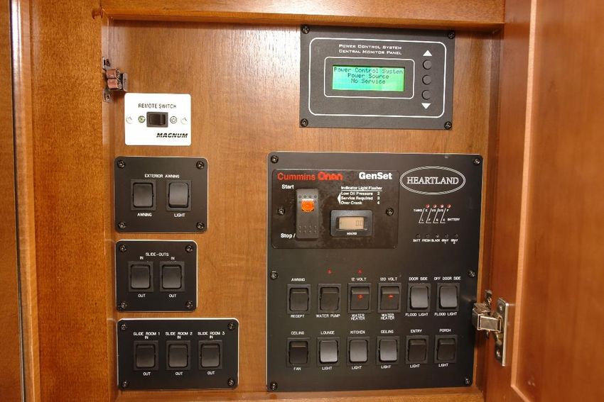
Heartland Owners Forum                                                                                    http://manuals.heartlandowners.org

       General Operation .............................................................................................................................. 15
       Cookware ............................................................................................................................................ 15
       Cleaning............................................................................................................................................... 16
   Residential Refrigerator .......................................................................................................................... 16
       Refrigerator Water Feed Line Cutoff Valve ......................................................................................... 16
       Overview of electrical and inverter..................................................................................................... 17
   Microwave/Convection Oven ................................................................................................................. 18
       Vent ..................................................................................................................................................... 18
       General Usage Notes .......................................................................................................................... 18
   Washer/Dryer ......................................................................................................................................... 19
   Dishwasher.............................................................................................................................................. 19
       Winterizing the Dishwasher ................................................................................................................ 19
Plumbing ..................................................................................................................................................... 20
   Universal Docking Center (UDC) ............................................................................................................. 20
       Anderson 4-way valve ......................................................................................................................... 20
       Black Tank Flush Connection(s)........................................................................................................... 22
       Safe Practices ...................................................................................................................................... 22
       Tank Valve Handles ............................................................................................................................. 23
   Water Filter ............................................................................................................................................. 25
       Water Filter Winterization .................................................................................................................. 25
       Initial Installation ................................................................................................................................ 25
       Tips When Changing the Filter Element.............................................................................................. 25
   Water Pump ............................................................................................................................................ 26
   Fresh Tank Fill ......................................................................................................................................... 26
   Fresh Tank Drain ..................................................................................................................................... 27
   Filling the Fresh Tank From a Water Container ...................................................................................... 27
   Low Point Drains ..................................................................................................................................... 27
   Studor Air Admittance Valves ................................................................................................................. 27
Heating and Cooling .................................................................................................................................... 28
   Furnace ................................................................................................................................................... 28
       Furnace Air Return and Floor Registers .............................................................................................. 29
       Air Conditioner Runs When Furnace Runs .......................................................................................... 29

Landmark 365 User Guide V1.1.pdf                                         Page |4                                      Version 1.1, March 10, 2016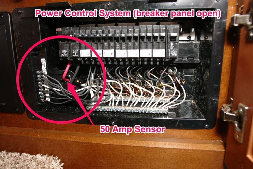
Heartland Owners Forum http://manuals.heartlandowners.org
Air Conditioning ...................................................................................................................................... 29
Air Conditioner Heat Pump Option ..................................................................................................... 29
Cleaning return filters ......................................................................................................................... 30
What happens when available power is not enough ......................................................................... 31
12V DC Electrical ......................................................................................................................................... 31
Fuse Box .................................................................................................................................................. 31
Checking for Blown Fuses ................................................................................................................... 32
Batteries .................................................................................................................................................. 32
Battery Cutoff Switches ...................................................................................................................... 32
Keeping Batteries Charged While Storing the Trailer ......................................................................... 33
Using an On-board Generator to Charge Batteries While in Storage ................................................. 33
Restarting the Residential Refrigerator Power System ...................................................................... 33
Power Converter ..................................................................................................................................... 34
Buss Bar and 12V Mini-Circuit Breakers ................................................................................................. 34
Hydraulics Pump Circuit Breaker ........................................................................................................ 36
Intermittent Operation of Leveling System or Slide outs ................................................................... 36
Differences From These Pictures ........................................................................................................ 36
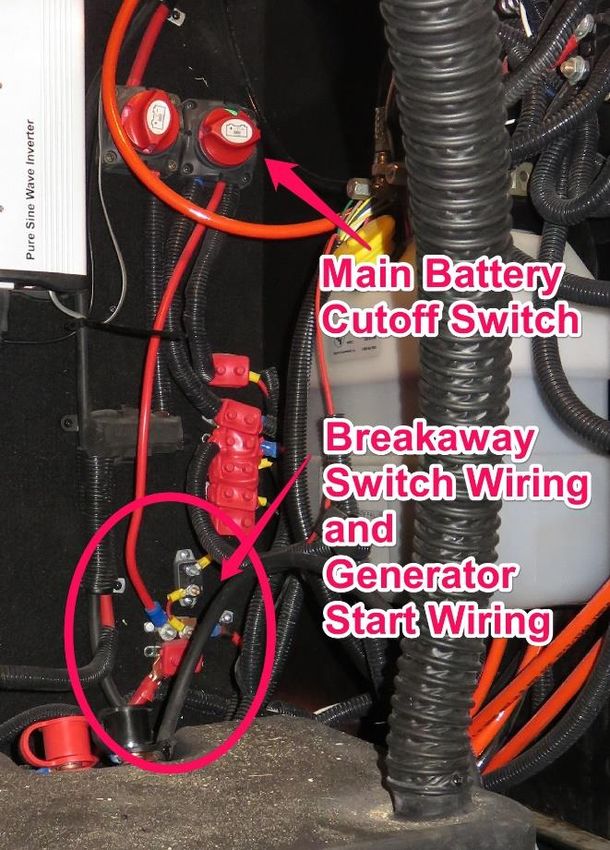
Power to Breakaway Switch and Generator Start .............................................................................. 37
Residential Refrigerator Inverter ............................................................................................................ 37
120V AC Electrical ....................................................................................................................................... 38
Circuit Breaker Panel............................................................................................................................... 38
Generator Prep Automatic Transfer Switch and Surge Protector .......................................................... 39
Built-in Surge Protector ...................................................................................................................... 40
Residential Refrigerator Automatic Transfer Switch .............................................................................. 40
GFCI Outlet .............................................................................................................................................. 41
Surge Protection & Electrical Management Systems ............................................................................. 41
Power Control System ................................................................................................................................ 42
Description of Operation ........................................................................................................................ 42
Reading the Precision Circuits Display .................................................................................................... 43
Prioritization of Load Shedding ............................................................................................................... 44
Line Status ............................................................................................................................................... 44
Entertainment Center ................................................................................................................................. 44
Landmark 365 User Guide V1.1.pdf Page |5 Version 1.1, March 10, 2016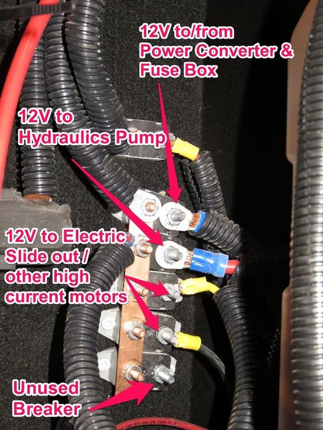
Heartland Owners Forum                                                                                  http://manuals.heartlandowners.org

   Watching Cable TV .................................................................................................................................. 44
       Signal booster ..................................................................................................................................... 44
       Cable TV Set Top Boxes ....................................................................................................................... 45
   Watching Over-the-Air Antenna TV ........................................................................................................ 46
       Operating the antenna pointer ........................................................................................................... 46
       TV Menu Settings ................................................................................................................................ 46
   Satellite TV .............................................................................................................................................. 47
       External Connections .......................................................................................................................... 47
       Internal Connections ........................................................................................................................... 48
       Rooftop Mount ................................................................................................................................... 49
   Sound Bar and Subwoofer ...................................................................................................................... 49
Landing Gear and Leveling System ............................................................................................................. 49
   Control Panel Operation ......................................................................................................................... 49
   Manual Leveling ...................................................................................................................................... 50
   If The Wheels are Lifted Off the Ground................................................................................................. 50
   Zero Level Calibration ............................................................................................................................. 51
   Manual Pump Operation ........................................................................................................................ 51
Revision History .......................................................................................................................................... 52

Landmark 365 User Guide V1.1.pdf                                       Page |6                                     Version 1.1, March 10, 2016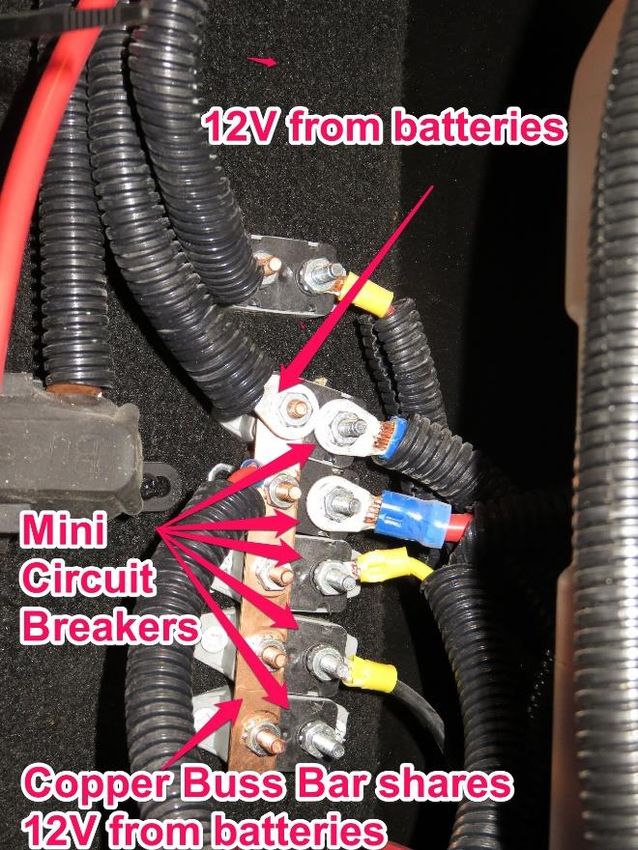
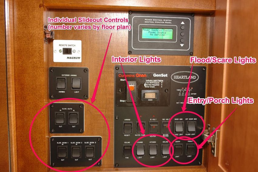
Heartland Owners Forum                                                http://manuals.heartlandowners.org

Landmark 365 User Guide
Landmark Evolution to the Landmark Three Sixty Five

Heartland RV’s first product was the 2005 model year Landmark, released in mid-2004. Since
then, Landmark has gone through many changes. In mid-2014, Heartland re-launched the
Landmark as the Landmark 365 product. Landmark 365 was designed with the full-timer and
any-timer RVer in mind.

While some aspects of this guide would apply to all Landmarks, many items covered are
Landmark 365 specific.

Introduction to Landmark 365 Features
There’s a lot to cover in a Landmark 365, but the Control Panel is central to using the coach. Let’s start
there.

Control Panel

Most controls for the Landmark 365 are grouped together and are labeled clearly. Additional
explanation follows on several controls.

Landmark 365 User Guide V1.1.pdf                Page |7                      Version 1.1, March 10, 2016
Heartland Owners Forum                                                http://manuals.heartlandowners.org

Slide Operation
Landmarks have individual controls allowing you to operate each slide independently of the others. This
allows you to open and close the slides in the sequence that best fits your needs. For example, at
roadside rest stops, it’s possible to extend the kitchen slide by itself to prepare lunch or grab a snack.
Note that it’s a good idea to let go of the rocker switch as soon as the slide reaches full extension or
retraction. If you don’t, the pump will continue to run under a higher than normal load.

Exterior Lights
Flood / Scare Lights / Porch Light / Entry Light
Flood lights, sometimes known as “scare” lights, are mounted near the roof on each side. On the right-
hand side of the panel there are individual rocker switches for the light on each side. There’s also a
switch for the porch light located over the outside steps, and for the entry light, located in the ceiling,
just as you walk into the coach. The entry light is also used by the “Welcome Back Feature” which is
explained more fully later in this document.

Step Light
There is a light located below the entry door, behind the steps, to help illuminate the steps at night. The
switch is located in the control panel, but is not typically marked. Location of the switch in the control
panel area will vary depending on floor plan.

Landmark 365 User Guide V1.1.pdf                Page |8                      Version 1.1, March 10, 2016
Heartland Owners Forum                                               http://manuals.heartlandowners.org

Interior Lights
The “lounge”, “kitchen” and “ceiling” ceiling lights on the Landmark use extremely low power/low heat
LED fixtures. This reduces power consumption when running on battery power and reduces heat load
when running the air conditioning. Each has its own rocker switch along the bottom row of switches on
the control panel.

Night Lights
To help find your way to the bathroom or kitchen at night, several floor-level night lights can be turned
on with a single switch. There’s a switch at the entrance to the bedroom, and another near the stairs.
The two switches operate in a 3-way configuration where either switch will operate all the lights.

Welcome Back Light
When you open the main entrance door, a switch under the door frame activates the Welcome Back
Light feature, turning on the ceiling entry light over the doorway. This allows you to enter the coach,
and turn on other lights without fumbling in the dark. The light goes out automatically after a pre-
programmed interval. The Welcome Back Feature is disabled when the Entry Light switch is turned ON.

Landmark 365 User Guide V1.1.pdf               Page |9                       Version 1.1, March 10, 2016
Heartland Owners Forum                                           http://manuals.heartlandowners.org

Tank Gauges

Pressing a small button under each indicator lights up the display to show the water level in each
holding tank and the approximate voltage level of the 12V DC power system. The Gauges give a very
rough indication and can be affected by how level the coach sits, and other factors.

Water Heater Electric

The dual-mode water heater can be operated in electric-only mode, LP mode, or both at the same time.

Landmark 365 User Guide V1.1.pdf            P a g e | 10                 Version 1.1, March 10, 2016
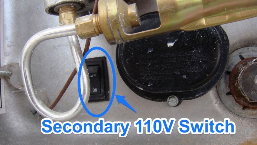
Heartland Owners Forum                                              http://manuals.heartlandowners.org

The switch marked “12 Volt’ uses 12 volt DC power from the batteries (when boon docking) or Power
Converter (when on shore power) in conjunction with propane to heat the water with a flame.

The switch marked “120 Volt” uses 120 Volt AC (when plugged into shore power) to heat a heating
element that raises the temperature of the water.

Checking for water in the water heater
Before turning the water heater ON, you must verify that there is water in the water heater tank.
Normally, when RVs are winterized, and when shipped from the factory, the water heater is drained and
the Bypass Control prevents water from entering the tank. Don’t assume that your dealer has set the
water system to normal operation and filled the water heater tank for you.

The Bypass Control must be set back to the normal operating position and the tank filled prior to turning
the water heater ON. If the 120 Volt switch is turned ON with an empty tank, you will quickly burn out
the heating element.

If you’re not sure whether there is water in the tank, consult the Water Heater Usage Guide.

Secondary Switch
On new trailers with Suburban Water Heaters, to protect you from accidently applying power to the
electric heating element, there is a secondary switch on the outside of the water heater. The exterior
cover must be removed to access the switch, which is located in the lower left corner. There may be a
cotter pin holding the switch in the OFF position. Atwood water heaters do not have this switch.

Water Heater Anode Rod
Suburban water heaters use a sacrificial anode rod to protect the tank lining from electrolytic damage.
(Atwood uses a different tank liner material and doesn’t need an anode rod). Heartland ships the anode
rod uninstalled. The dealer should have installed it for you, but you should check that it’s installed

Landmark 365 User Guide V1.1.pdf              P a g e | 11                 Version 1.1, March 10, 2016
Heartland Owners Forum                                               http://manuals.heartlandowners.org

before connecting water the first time. Remove the outer cover of the water heater to check. The
anode rod is a maintenance item that you should plan on replacing annually.

Water Heater Usage Guide
For more detailed information about your Water Heater, consult our owner-written Water Heater Usage
Guide.

Water Heater 12 Volt / Propane Operation
Turning the 12 Volt Water Heater switch ON should start the propane side of the heater as long as
propane is flowing and your batteries/power converter are providing approximately 12V DC.

Once the switch is turned ON, a small indicator light will illuminate for about 15 seconds to let you know
that the ignition sequence is underway. When the burner is lit, the light will go out. During the 15
seconds, the control board will attempt to purge air from the propane feed line and will attempt to light
the propane burner 3 times. If it fails, the water heater will lock the LP operation for safety reasons and
the light will stay on. To clear the lockout, turn the switch off for 10 seconds and then turn on again to
retry. Note that if the water in the tank is already heated, the ignition sequence may not occur until the
water cools a bit.

Yeti Package - Tank Heaters and Heat Tape
The optional YETI package includes 120V AC powered tank heating pads on each holding tank along with
12V DC powered heat tape on the portion of the fresh water feed line in the underbelly. One switch
turns on all the tank heating pads. The other switch turns on the heat tape so that the water line from
fresh tank to the pump doesn’t freeze.

Landmark 365 User Guide V1.1.pdf               P a g e | 12                  Version 1.1, March 10, 2016
Heartland Owners Forum                                                http://manuals.heartlandowners.org

In sub-freezing weather, if the heat tape is not turned on before temperatures drop, you may have ice at
the junction where the fresh tank drain hose is teed into the feed line. The water above the drain valve,
and below the coroplast is first to freeze and ice can wick up into the tee fitting, blocking water flow.

 Caution: you must have a few gallons of water in the holding tanks when the tank heaters are turned
 on. Heating empty tanks may result in damage to the tank.

While heat tape is designed to keep water in the line from freezing, once there’s a block of solid ice, it
could take quite a while to thaw. If this happens, using a hair dryer on the fresh tank drain hose may
speed up thawing the line.

Ceiling Fan
The control panel switch turns the interior 120V AC powered ceiling fan on (if so equipped). There may
also be a pull chain on the fan to control the speed. Repeatedly pulling the chain will cycle it through
the various speed settings and OFF. There may also be a switch on the fan to reverse direction. In warm
weather, set the fan to rotate so that air is pushed down. In cool weather, set the fan to rotate so air is
pulled up. As the fan turns, if the leading edge of the fan blade is higher, air will be pushed down. If the
leading edge is lower, air will be pulled up.

Miscellaneous Controls

Landmark 365 User Guide V1.1.pdf                P a g e | 13                  Version 1.1, March 10, 2016
Heartland Owners Forum                                                http://manuals.heartlandowners.org

Water Pump Switch
The Water Pump switch provides power to the water pump for times when the coach is not connected
to city water. The water pump pulls water from the fresh water holding tank and pumps it through the
plumbing using the same lines that city water follows. The pump has a pressure sensor that detects the
drop in pressure that occurs when a faucet is opened. If the pump has 12V DC power, when the
pressure drops, the pump begins pumping water. When you close the faucet, pumping continues for a
short time until the pressure sensor detects that normal pressure has been restored in the lines.

Note that when using fresh tank water, in addition to having the pump turned ON, the 4-way Anderson
Valve in the Universal Docking Center (UDC) must be set to NORMAL. This setting enables water from
the fresh tank to flow through the 4-way valve to the faucets and other fixtures. If not in NORMAL
mode, the pump will run for a short time but no water will come through the faucets.

 CAUTION: If you hear the water pump running when faucets are closed, it’s critical to find the cause
 without delay. While it could be due to a malfunctioning pressure switch, it’s more likely there is a
 water leak somewhere in the plumbing system. If not corrected, water leaks can lead to extensive
 damage. If you are unable to resolve the problem, the pump switch should be turned OFF to prevent
 damage to your coach.

When using city water, it’s a good practice to leave the Water Pump switch OFF. It’s also a good
practice to leave the switch OFF when towing and when leaving the coach for long periods.

Note that pets have been known to jump onto kitchen counters and rub against the faucet controls,
turning water on. If you leave the pump turned on with gray tank valves closed, you could return to find
the interior of your RV flooded.

Awning Switches
The Awning switch extends or retracts the main patio awning. The Awning Light switch turns on the LED
strip mounted on the coach sidewall, along the awning. With the optional exterior TV, a separate patio
awning is provided for the TV area outside the coach. A separate awning switch for the TV awning is
usually located inside, near the entrance door.

Awning Receptacle Switch
The Awning Receptacle switch turns on 120V AC power to an exterior outlet located near the front of
the main awning. This allows you to hang lights on the awning or nearby and turn them on and off
without going outside.

Inverter Remote Switch
When towing, your batteries supply power to an inverter that converts 12V DC into 120V AC to power
the Residential Refrigerator. Any time that 12V power is turned off, either by removing batteries for
service or when in storage, or by turning the battery cutoff switch(es) to OFF, the inverter will turn off
and stay off when power is reconnected. The remote switch may be used to turn the inverter ON,
provided the battery cutoff switches are ON.

Landmark 365 User Guide V1.1.pdf                P a g e | 14                  Version 1.1, March 10, 2016
Heartland Owners Forum                                               http://manuals.heartlandowners.org

Some owners have asked about leaving the inverter ON when camping and connected to shore power.
This is an acceptable practice and provides protection in case the power goes out in the campground.

When preparing to leave on a trip, after shore power is disconnected, it’s a good practice to check the
light on the Inverter Remote Switch to ensure that the inverter is ON. Also check that the refrigerator is
ON.

Inverter Status Indicator Light Modification
 Some owners have installed a simple modification to their coaches in order to monitor inverter status
while towing. They have installed a bright green or yellow LED light on the front wall of the trailer,
under the pin box overhang. The LED is powered from the inverter’s spare 120V AC outlet using a 120V
AC to 12V DC adapter. When towing, every time the driver looks in the left side mirror, the LED will
confirm that the inverter is supplying power to the refrigerator.

Here’s a link to a detailed description of this modification.

Pass-thru Storage Lights and Front Storage Compartment Light
The pass through basement storage has several lights on the front wall with individual on/off switches
on each light. In addition, there is a master on/off switch next to the Auto Leveling control panel. If the
individual light switches are ON, you can operate both lights by using the switch next to the control
panel.

There is also a light inside the front compartment, with an on/off switch inside the compartment, on the
right side.

Appliances

Induction Cooktop
General Operation
The induction cooktop operates by heating the cookware without heating the surface of the cooktop.
This technology allows for more precise temperature control and generally achieves cooking
temperature faster than standard gas or electric burners.

If you’re new to induction cooktops, you should read the entire manual that came with yours. Appliance
manuals are typically in a blue pouch stored in one of your cabinet drawers.

Cookware
Induction cooking requires cookware made of ferrous material (iron). If the original cookware
packaging is available, it should indicate whether it’s compatible with induction cooktops. If you’re
not sure, make sure a magnet sticks to the bottom of the pot or pan.

Landmark 365 User Guide V1.1.pdf                P a g e | 15                 Version 1.1, March 10, 2016
Heartland Owners Forum                                                http://manuals.heartlandowners.org

For best results, use cookware with a flat bottom. Size is also important. The bottom should have a
diameter of 4.5” to 10”. Round bottom pans will give best results. Do not use cookware that is
warped.

Cleaning
Use a damp cloth to wipe off the glass ceramic surface of the cooktop. Take care that water
doesn’t seep into the device. Never use abrasive cleaners or oil-based liquids.

Residential Refrigerator
The residential refrigerator is 120V AC only. Because it has been designed for use in residences, it does
not run on propane as RV gas absorption refrigerators do. A continuous supply of 120V AC is required
for proper operation.

In order to provide 120V while towing, there is an inverter to convert 12V DC from the batteries into
120V AC for the refrigerator. This is described in more detail below.

In your sticks and bricks home, it’s generally not necessary to winterize the refrigerator. However,
before storing the RV for the winter, it is critical to properly winterize the refrigerator in your RV. This
includes components inside the refrigerator and outside the refrigerator. Detailed instructions may be
found in our Residential Refrigerator User Guide. Note that Heartland changes refrigerator models and
suppliers over time, so the guide may not reflect the actual location of controls inside your refrigerator.

Even if you’re living in the RV all year round, if temperatures are forecast to drop below freezing, you’ll
need to winterize the water feed line that supplies the refrigerator (if so equipped). There are parts of
the line, and a drain valve, exposed to outside air. The poly line and drain valve may be damaged in a
freeze. Refer to the Residential Refrigerator Guide for instructions on winterizing the water feed line.

Refrigerator Water Feed Line Cutoff Valve
The water feed line that supplies the ice maker has a cutoff valve inside the coach. On most floor plans,
it will be located either under the sink, or under and behind the bottom drawer to the left of the sink.

Landmark 365 User Guide V1.1.pdf                P a g e | 16                  Version 1.1, March 10, 2016
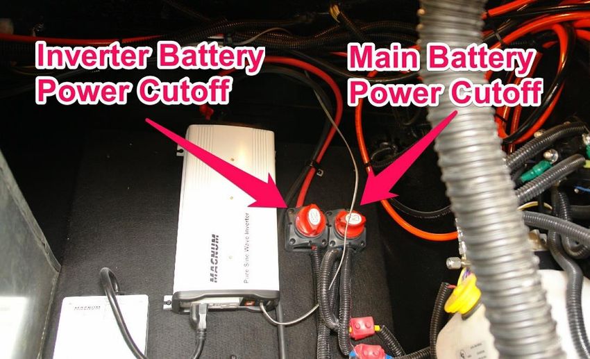
Heartland Owners Forum                                             http://manuals.heartlandowners.org

Overview of electrical and inverter
The batteries are connected to an inverter that changes 12V DC into 120V AC. The inverter output goes
to an automatic transfer switch (some inverters may have a built-in transfer switch). When connected
to shore power, the transfer switch routes shore power to the refrigerator. When shore power is
disconnected, the transfer switch routes the inverter output to the refrigerator.

In order to conserve battery power when not using the coach, both the refrigerator and the inverter
should be turned off. The inverter can be turned off using the remote button in the control panel, or by
operating the Inverter Battery Power CUTOFF switch in the front storage area. The pictures below
shows the cutoff switches that are in the front compartment and the inverter remote button that is
inside the coach.

 NOTE: After switching the battery cutoff switch ON, you must manually restart the inverter or
 the refrigerator will not receive any power from the batteries. If you are plugged into shore
 power while loading up for a trip, the refrigerator will run on 110V shore power. But if you
 forget to turn on the inverter, when you begin towing, the refrigerator will not receive power.

Landmark 365 User Guide V1.1.pdf              P a g e | 17                 Version 1.1, March 10, 2016
Heartland Owners Forum                                                http://manuals.heartlandowners.org

Microwave/Convection Oven
Vent
The exterior vent cover needs to be opened before cooking so that hot air can be vented from the
microwave/convection oven. You’ll probably need a step ladder to reach the vent.

  CAUTION: Microwave/Convection ovens usually have over-temperature sensors used as a safety
  feature to interrupt power if the interior of the oven overheats. Once triggered, these sensors
  have to be replaced, which may require help from a technician trained on ovens. Using the oven
  with the vent closed could cause overheating that causes a safety shutdown.

Looking up on the exterior wall of the coach, you’ll see two tabs on the bottom corners of the vent. To
release the vent, push up on both tabs at the same time and as they release, pivot the bottom edge of
the vent cover outward. The vent cover tabs are often quite stiff and may require quite a bit of force to
release the cover.

Photo by JohnD

Most owners leave the vent open while traveling. During storage, it’s probably a good idea to close it.

General Usage Notes
Microwave/Convection ovens can typically be used either as microwave oven, or as a convection oven
(where the hot air is circulated to reduce cooking time), or on some ovens, in a combination mode to
speed cooking even further.

On many convection ovens, temperature settings may not be quite the same as with conventional gas or
electric ovens. Recipes often must be adapted slightly to convection ovens.

If this is your first experience with convection oven cooking, you may find it helpful to consult a
cookbook devoted to convection oven cooking.

Landmark 365 User Guide V1.1.pdf                P a g e | 18                  Version 1.1, March 10, 2016
Heartland Owners Forum                                               http://manuals.heartlandowners.org

Washer/Dryer
The washers and dryers made for RVs are typically smaller capacity units than those found in most
homes. You’ll find that the RV washer and dryer work better with half-size loads.

RV dryers are supplied with 120V AC whereas home dryers are usually 240V. The additional power
allows the home dryer to dry a load of clothes much quicker. RV dryers take longer.

Consult the washer and dryer manuals that came with your RV for specific operating instructions.

Before storing the RV for the winter, you will have to take several specific steps to winterize the washer
correctly. See our owner-written Winterization Guide for directions on winterizing the washing machine
and protecting the water lines and drain.

If you have washer/dryer prep, but do not have the washer, you still need to winterize those water lines.

Dishwasher
Consult your dishwasher manual for operating instructions.

Winterizing the Dishwasher
The dishwasher should be winterized before storing the RV for the winter. Dishwashers drain systems
will typically hold a little water at the end of a wash cycle. There may also be water in the drain hose
because it tees into the drain line higher than the fitting on the dishwasher.

The example below uses a combination of compressed air and RV antifreeze to protect the dishwasher.

Use the instructions and pictures that follow to winterize the dishwasher. The drain line can be
accessed at the rear of the dishwasher by opening the cabinet door.

1.  Winterize the rest of the coach first. Here’s a link to our owner-written Winterizing Guide.
2.  Set your air compressor to 40 psi.
3.  Press Power Button on Dishwasher to turn it on
4.  Set Program Cycle to Heavy (or any cycle)
5.  Shut Dishwasher door and dishwasher will start
6.  Dishwasher will call for water. Most of the water in the coach lines will be gone. A bit of
    residual water may enter the dishwasher along with compressed air during the beginning of
    the wash cycle. Allow it to run for up to 3 minutes until you hear the dishwasher drain pump
    start and then stop
7. At the back of the dishwasher, place a towel below the drain line connection (lower left)
8. Grab a shallow bowl and a small dish/hand towel. Place the towel in the cabinet below the
    drain
9. Using hand-pressure only, remove the drain line and place the bowl below the drain to allow
    any water to be caught in it. Empty the bowl outside or in the toilet, then put it back in place
    under the drain. Leave the drain line disconnected
10. Press Power Button on Dishwasher to turn it off
11. Pour a cup of RV Antifreeze into the bottom center of the dishwasher
12. Repeat steps 3 through 6 and step 10. About a cup of liquid should empty from the
    dishwasher into the bowl. Much of it will be antifreeze. Pour this down the toilet bowl

Landmark 365 User Guide V1.1.pdf               P a g e | 19                 Version 1.1, March 10, 2016
Heartland Owners Forum http://manuals.heartlandowners.org
13. Repeat steps 3 through 6 and step 10 again. This time, the liquid should be 100%
antifreeze. Here again, pour that antifreeze into the toilet bowl
14. Press Power Button on Dishwasher to turn it off
15. Reconnect the drain line – hand tighten
Plumbing
Universal Docking Center (UDC)
Anderson 4-way valve
The Anderson 4-way valve simplifies water hookups. The four positions on the selector allow you to
select the various functions without changing the water hose connection.
Landmark 365 User Guide V1.1.pdf P a g e | 20 Version 1.1, March 10, 2016Heartland Owners Forum http://manuals.heartlandowners.org City When connected to a campground water faucet, the selector should be on City. This allows the campground water to flow directly to your water faucets, shower, and toilet. On the City setting, a channel is also open to allow water to be pumped from the fresh tank when the pump is turned on. This allows you to use the pump at rest stops without having to change the setting of the 4-way valve. Normal Anderson uses the term “Normal” to describe using the water in the fresh water holding tank in conjunction with the water pump to deliver water to your faucets. Setting the selector to Normal connects the fresh tank feed line to the water pump input. The pump must also be turned ON. Sanitize/Winterize When set to Sanitize/Winterize, the hose connected to the Anderson Valve water inlet will feed incoming fluids to the input (suction) side of the water pump. If the water pump is turned on, it will suck fluid from the hose, through the pump, and out to the faucets, shower, toilet, washing machine, outside shower. To sanitize, you can disconnect your city water hose and fill it with a bleach solution as directed in your Heartland Trailer Manual (1/4 cup of bleach to 1 gallon of water). Then connect it to the water inlet and use the pump to suck the mixture through the water lines to the faucets, etc. To sanitize the fresh water tank, you’ll need to use the same technique with the selector set to Tank. Use city water to push the bleach solution into the fresh tank. When sanitizing, refer to your Heartland Trailer Manual for additional steps. Landmark 365 User Guide V1.1.pdf P a g e | 21 Version 1.1, March 10, 2016
Heartland Owners Forum                                                 http://manuals.heartlandowners.org

For winterizing instructions, refer to the Winterization Guide.

Tank
To fill the fresh water holding tank, set the selector to Tank and with hose connected, turn on the
campground water faucet. The fresh water holding tank has overflow hoses. When the tank is full,
water will come out of the overflows on each side of the frame.

Black Tank Flush Connection(s)
There is a separate water inlet connection for the black tank flush. And if your RV has a 2nd bathroom,
there is a second connection to flush that black tank.

The black tank flush allows you to run campground water through a sprayer mounted inside the black
tank in order to help clean out the tank.

Safe Practices
It’s a good practice to use a different, clearly marked hose for the black tank flush. Although the routing
of the black tank flush water lines, and the use of a vacuum breaker valve, will help prevent
contamination of the water hose, it’s a good practice to use a different hose to provide additional
protection against contamination in the event of a valve failure. Some owners add an additional check
valve to the Black Tank Flush Inlet to provide further protection against contaminating hoses or the
campground faucet.

Whenever water is running through the Black Tank Flush, you should either have the black tank gate
valve in the open position, or if the gate valve is closed, you should take great care to avoid overfilling

Landmark 365 User Guide V1.1.pdf                P a g e | 22                   Version 1.1, March 10, 2016
Heartland Owners Forum                                                http://manuals.heartlandowners.org

the tank. Using the timer function on your smart phone is one way to keep track of how much water is
being added to the black tank through the flush system. If you assume water flow of 5 gallons per
minute, setting a timer for 6 minutes will add about 30 gallons to the black tank. If you’ve emptied the
tank and are filling it with the Black Tank Flush to facilitate a 2nd emptying, 30 gallons should be enough.

 CAUTION: Overfilling the black tank can create a huge mess inside the RV and could damage the
 tank and/or plumbing connections. Do not allow yourself to be distracted while operating the Black
 Tank Flush. It’s also a good idea to notify other parties using the trailer that you are dumping the
 tanks, so they know not to use the toilet. If the tank is overfilled, there will be upward pressure on
 the toilet, sewage may rise into the vent that goes to the roof and could pour out on the roof and
 run down the sides of the RV. Sewage can also escape into the underbelly if tank connections are
 forced apart by the internal pressure. Using a timer will help avoid these scenarios.

If your floor plan has a 2nd bathroom, there will be a separate black tank for that bathroom, along with a
separate Black Tank Flush Inlet for that tank.

Tank Valve Handles
In a single bathroom floor plan, the holding tank gate valve pull handles are located in the UDC. The
bottom handle is for the Black tank. The middle handle is for Gray #2, which is the galley. The top
handle is for Gray #1, which collects water from the bathroom sink and shower, and the washing
machine.

Landmark 365 User Guide V1.1.pdf                P a g e | 23                  Version 1.1, March 10, 2016
Heartland Owners Forum                                                http://manuals.heartlandowners.org

In floor plans with a 2nd bath, the pull handles are arranged differently. Gray #1 is still on top. The
middle and bottom pull handles are for the two black tanks. The bottom pull handle is for the main
bathroom black tank. The middle handle is for the 2nd bathroom black tank.

In floor plans with a 2nd bath, the pull handle for Gray #2 has been relocated and is inside a
compartment door near the UDC.

For additional information along with tips and techniques for keeping your holding tanks clean, consult
our owner-written Water Systems Guide.

Landmark 365 User Guide V1.1.pdf               P a g e | 24                   Version 1.1, March 10, 2016
Heartland Owners Forum                                               http://manuals.heartlandowners.org

Water Filter

Landmark 365 units come with a single-stage water filter located behind the Universal Docking Center
(UDC). To gain access, you will need to remove the rear wall of the pass-through basement storage,
next to the UDC. Many owners have modified that panel to allow easier access to the filter and water
pump.

Most water filters that handle all water coming into the coach, as this one does, should be changed at
least once every 6 months and perhaps every 3 months, depending on the quality of water coming into
the coach. Particulates in the water supply at many campgrounds can clog the filter, reducing water
flow. It’s also important to change the filter to prevent bacterial buildup.

Water Filter Winterization
When winterizing the coach, the filter element should be removed from the canister before introducing
antifreeze or compressed air.

Initial Installation
The water filter element is not installed in the canister when Heartland ships the RV to the dealer.
While it’s possible the dealer may have installed it for you, you should check. Since the dealer doesn’t
always know when or how soon you’ll be using the coach, they may have left it to you to install.

Tips When Changing the Filter Element
First of all, turn off the campground water faucet and/or the water pump. Open a faucet in the coach to
relieve pressure. Then use the canister tool to loosen the canister. Unscrew the canister. As it’s pretty
easy to spill water when opening the canister, placing a bucket underneath, or surrounding the canister
with a trash bag while opening it will catch any water spills.

Landmark 365 User Guide V1.1.pdf               P a g e | 25                 Version 1.1, March 10, 2016
Heartland Owners Forum                                               http://manuals.heartlandowners.org

When closing the canister, make sure the rubber O-ring/gasket is placed correctly and is not pinched.
Hand tighten until snug. Before replacing the pass-through storage wall, re-open the campground water
faucet and/or turn on your water pump and check for leaks.

Water Pump

The water pump is located behind the UDC, on the floor below the water filter. When winterizing, the
pump will suck antifreeze in and pump it through the water system (but not into the fresh tank or
through the black tank flush systems). However, if using compressed air to winterize, you must take
additional steps to protect the water pump and its filter assembly. Consult our Winterization Guide for
details.

It’s a good practice to check the fittings on the input and output of the pump periodically to ensure
they’re snug. Also check the clear filter bowl on the input side. They should all be hand tight.

Fresh Tank Fill
To fill the fresh water holding tank, the 4-way Anderson Valve must be set to TANK and you must
connect a water source to the water inlet. As the tank reaches full capacity, the water will come out the
overflow fittings on the outside of the frame. There is usually a pex line and 90 degree fitting that
terminate on the door side, just to the rear of the entry steps. There may also be another drain on the
off-door-side. The picture here shows where how the overflow comes out of the tank and through the
frame. Additional PEX tubing is connected to route the water toward the middle of the coach.

Landmark 365 User Guide V1.1.pdf               P a g e | 26                  Version 1.1, March 10, 2016
Heartland Owners Forum                                                http://manuals.heartlandowners.org

Fresh Tank Drain
The drain for the fresh water holding tank is located on the off-door-side, near the axles. There is
typically an 8-12” length of pex sticking out from the coroplast, with a valve that is opened to drain the
tank.

Filling the Fresh Tank From a Water Container
The city water inlet has a built-in check valve to prevent water from spurting out the inlet while using
the water pump. A certain amount of water pressure is required to operate the check valve. Normally
when hooked up to a faucet, the city/campground water supply provides enough pressure to operate
the valve so that water will go through it.

If you are boon docking and want to add water to the fresh tank from a container, there probably won’t
be enough pressure to operate the check valve. Some owners have obtained inexpensive pumps to put
in-between the water container and city water inlet. The pump will provide enough pressure to operate
the check valve. If you’re boon docking, a 12V DC pump will work without the use of a generator.

Low Point Drains
The Landmark 365 does not have low point drains. On trailers with low point drains, in cold weather,
the water between coroplast and drain valve can freeze allowing ice to wick into the tee, blocking water
flow. To avoid that problem, the Landmark 365 has no low point drains. There is still a fresh tank drain
poking through the coroplast, on the off-door-side, near the front axle. There may also be an overflow
drain for the washing machine.

Studor Air Admittance Valves
Sink drains have p-traps that hold a small amount of water to block sewer gas from entering the coach.
When draining a sink, a vacuum effect can suck the water out of the p-trap. To prevent this, and to
facilitate fast draining, the drain lines are typically vented through the roof. However, in some
configurations, it’s not practical to use a roof vent. A kitchen island may be one of those configurations.

Landmark 365 User Guide V1.1.pdf               P a g e | 27                  Version 1.1, March 10, 2016
Heartland Owners Forum                                                http://manuals.heartlandowners.org

To provide venting, a Studor Air-Admittance Valve is used. The vacuum effect causes the one-way valve
to open, admitting air, which breaks the vacuum and prevents the water in the p-trap from being sucked
out.

If the Studor Valve sticks open or fails altogether, sewer gas can enter the coach through the valve.
Replacement valves are inexpensive and can be obtained at most big-box hardware stores.

While failure of the Studor Valve is not all that common, if you have a persistent sewer odor in the
coach, you should check under the sink to see if a Studor Valve is present. Cover it with a plastic baggy
secured by a rubber band. If the odor goes away, the valve should be replaced.

Heating and Cooling
Furnace
The furnace is controlled by one of the air conditioner thermostats inside the coach. While you may
have up to three thermostats, with each thermostat controlling a separate air conditioning unit, only
one of those thermostats is wired to control the furnace - usually the rearmost thermostat.

The thermostat will cycle the furnace on and off based on the ambient temperature at the location of
that thermostat. Temperatures inside a 40 foot long RV usually differ by several degrees from front to
rear. Also, warm air rises, so a front bedroom that’s higher than the living room will always have more
warm air than the rear of the coach. In addition, the furnace is usually located closer to the front of the
coach, pushing hotter air through the ducts to the front bedroom and bath. By the time air goes the
longer distance to the rear of the coach, it will not be as warm coming out of the rear floor registers.

You’ll need to set the thermostat to provide a comfortable temperature in the part of the coach that
you’re using at any particular time.

Landmark 365 User Guide V1.1.pdf               P a g e | 28                  Version 1.1, March 10, 2016
Heartland Owners Forum                                              http://manuals.heartlandowners.org

If you have a fireplace or other supplemental electric heat in the rear of the coach, you may want to set
the thermostat for comfort in the front bedroom and use the supplemental heat to keep the rear of the
coach comfortable.

Furnace Air Return and Floor Registers
It’s very important to never block the air return vents to the furnace. Doing so may cause intermittent
operation of the furnace because there’s not enough return air flow to allow the Sail Switch on the
furnace to operate reliably. When the Sail Switch doesn’t close, the furnace control board interprets
this as a safety issue and prevents the furnace from operating.

While some owners have partially or completely blocked one or more floor registers, the furnace
manufacturer strongly advises against doing so. Restricting airflow may result in overheating of the
combustion chamber inside the furnace. There is an over temperature sensor in that chamber that will
prevent the furnace from operating if temperatures get too high. The sensor could be weakened by
repeated operation and result in a furnace malfunction where the blower runs continuously but the
heat output is intermittent.

Air Conditioner Runs When Furnace Runs
If you turn on the furnace and the air conditioner blower starts running, along with the furnace, the fan
setting on the thermostat needs to be changed to AUTO. If set on HIGH or LOW, the fan will run
continuously any time the thermostat calls for either heating or cooling.

Air Conditioning
Each air conditioner has its own thermostat that turns on its respective unit based on the ambient
temperature at the thermostat location. While the thermostats may be capable of supporting multiple
zones, they are wired for single zone operation.

To minimize noise, you can adjust the thermostats so that the units furthest away from you are
providing cooling through the common duct system. At night, turn the living area thermostats lower
and the bedroom thermostat higher to minimize noise while sleeping. While watching TV downstairs,
set the bedroom thermostat lower and the living area thermostats higher to minimize noise in the living
area.

Air Conditioner Heat Pump Option
As an option, purchasers can select Air Conditioners that are also heat pumps. In essence, the unit can
run in a way that extracts heat from outside and moves it inside when in Heat Pump Mode. Heat Pump
Mode is selected on the thermostat. Note that in Heat Pump Mode, below about 30 degrees (F) outside
temperature, the Heat Pump will shut off and the thermostat that is connected to the furnace will start
the furnace.

Landmark 365 User Guide V1.1.pdf               P a g e | 29                 Version 1.1, March 10, 2016
You can also read