An overview of steganography techniques applied to the protection of biometric data
←
→
Page content transcription
If your browser does not render page correctly, please read the page content below
Multimed Tools Appl
https://doi.org/10.1007/s11042-017-5308-3

An overview of steganography techniques applied
to the protection of biometric data

Mandy Douglas 1 & Karen Bailey 1 & Mark Leeney 1 &
Kevin Curran 2

Received: 20 January 2017 / Revised: 31 August 2017 / Accepted: 13 October 2017
# The Author(s) 2017. This article is an open access publication

Abstract Identification of persons by way of biometric features is an emerging
phenomenon. Over the years, biometric recognition has received much attention due
to its need for security. Amongst the many existing biometrics, fingerprints are
considered to be one of the most practical ones. Techniques such as watermarking
and steganography have been used in attempt to improve security of biometric data.
Watermarking is the process of embedding information into a carrier file for the
protection of ownership/copyright of music, video or image files, whilst steganogra-
phy is the art of hiding information. This paper presents an overview of steganogra-
phy techniques applied in the protection of biometric data in fingerprints. It is novel
in that we also discuss the strengths and weaknesses of targeted and blind steganalysis
strategies for breaking steganography techniques.

Keywords Steganograpy . Biometrics . Image analysis . Security

* Mandy Douglas
  mandy.douglas@lyit.ie

    Karen Bailey
    karen.bailey@lyit.ie
    Mark Leeney
    mark.leeney@lyit.ie
    Kevin Curran
    kj.curran@ulster.ac.uk

1
    Institute of Technology, LetterkennyPort RoadCo. Donegal, Ireland
2
    Faculty of Computing and Engineering, Ulster University, Coleraine, Northern Ireland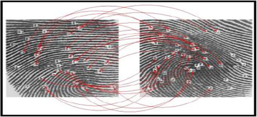
Multimed Tools Appl

1 Introduction

Biometric systems allow for convenient identification to take place based on a person’s
physical or behavioural characteristics. In comparison with conventional token-based or
knowledge based systems, they link identities directly to the owners. Moreover, these identities
cannot be given up or lost easily. The uses of biometric procedures have evolved rapidly in the
past decade and are used in many different areas, such as banking and government agencies,
retail sales, law enforcement, health services, and airport/border controls [3]. In recent years,
companies such as Apple and Samsung has integrated biometrics into their latest mobile
devices, which can now be unlocked with the owner’s fingerprint data [43, 64]. One of the
main reasons that these biometric mechanisms are gaining popularity is because of their ability
to distinguish between an authorized user and a deceptive one [52. At present, fingerprint
biometrics are said to be the most common mechanism, as these are convenient to use, and less
expensive to maintain in comparison to other systems. However, as the development of these
applications continues to expand, the matter of security and confidentiality cannot be ignored.
The security and integrity of biometric data presents a major challenge, as many benefits of
biometrics may quite easily become impediment. Thus, from the point of view of promoting
the extensive usage of biometric techniques, the necessity of safeguarding biometric data, in
particular fingerprint data becomes crucial [37]. For example, fingerprint biometric systems
contain sensitive information such as minutia points (explained in the next section) which is
used to uniquely identify each fingerprint. The use of latent fingerprints is one way that an
unauthorized user can access a system. A latent fingerprint can be easily collected as people
leave latent prints when they touch hard surfaces. If an unauthorized user was successful in
retrieving a latent print it may enable him/her to gain access to the system hence potentially
endanger the privacy of users. Additionally, stolen data may be used for illegal purposes, such
as identity theft, forgery or fraud. Therefore, increased security of the data is critical [51].
    There are procedures in existence that can help to optimize the security of biometric
data, one being, information hiding. Information hiding techniques like watermarking and
steganography can add to the security of biometric systems. Watermarking can be ex-
plained as a process of embedding information into a carrier file in order to secure
copyright, typically ownership [58]. Watermarks can be either visible or nonvisible to
the human eye. Steganography is the process of hiding critical data (i.e. identity pin) in a
trusted carrier medium (i.e. digital fingerprint image) without third parties sharing any
awareness that the information exists. Both methods of information hiding are closely
connected [24]. Steganography can be applied using the following two approaches:
reversible and irreversible [100]. A reversible data hiding technique, allows for a full
recovery of the original carrier file even after extraction of the hidden data. Whereas, an
irreversible technique may leave the original carrier file distorted after the hidden data is
extracted [88]. Over the past number of years, many image-based steganography methods
have been broadly classified depending upon the domain as spatial domain steganography
and frequency domain steganography. In Spatial domain steganography, methods such as
correlation based techniques, pixel value differencing and LSB substitution, which will be
explained later, have been developed and tested. Frequency domain steganography
methods consist of many different domains, such as Discrete Cosine Transform (DCT)
domain, Discrete Fourier Transform (DFT) domain, Discrete Wavelet Transform (DWT)
domain, Singular Value Decomposition (SVD). Frequency domain methods are consid-
ered to be more robust than that of spatial domain methods [46, 58, 93, 99].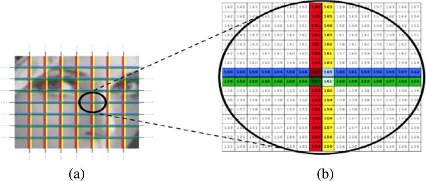
Multimed Tools Appl

   In recent years, frequency domain methods have been used in combination with other
techniques, this approach is known as hybrid steganography. Many of these hybrid techniques
make use of a mathematical decomposition called the Singular Value Decomposition. SVD is
considered to be one of the most valuable numerical analysis tools available, mainly because
singular values obtain inherent algebraic properties and provide stability that permits secret
data to be hidden without degrading the perceptual quality of an image [60, 107]. We next look
at biometric systems & biometric security.

2 Biometric systems & biometric security

Biometric systems are basically pattern recognition systems that function by obtaining unique
personal and biological characteristics from a human being for verification purposes. They use
physical qualities such as face recognition, hand geometry, fingerprints, iris sequences, and
personal attributes such as voice recognition, keystroke and handwriting patterns. The use of
biometric recognition includes various privacy perks. For instance, biometrics can exclude the
need to be mindful of numerous passwords and pin numbers hence there is no need to
remember them. Biometrics can also be used to restrain unauthorized users from gaining
access to mobile devices, computers, government buildings, bank machines, places of work
etc. Moreover, the same biometric data can be used consistently, for everything. Biometric data
can be divided into two categories: physiological features, which include DNA, face, hand
geometry, fingerprints, iris and retina, behavioural features, which include signature, gait and
voice. A person’s behavioural features may change during the course of their life, for that
reason regular sampling is necessary. In comparison, physiological biometric data requires
much less sampling [53].
   Biometric systems can operate in two modes, identification mode or verification mode.
Prior to the system being set up, firstly a database of reference data has to be created. The
database is used to store all the biometric templates, this process is known as the enrolment
process. [126]. The process of enrolment involves collecting biometric samples from the user,
samples are then evaluated, processed and saved as a template on a database for future use
[116].
   Verification systems attempt to determine BIs this person who they say they are?^ In
verification, sometimes referred to as authentication, the user presents the system with a
biometric trait so they can be identified as a specific person. The system then will
analyse the trait provided against data already stored in the database associated to the
user in order to find a match. If the data provided has a high degree of similarity to the
data stored in the database then the user is accepted by the system as being genuine.
Alternatively, the user is treated as a fake and will not gain the requested access to the
system. Verification system can be labelled as a one to one (1–1) matching system. In
comparison, identification mode is different, as it attempts to identify a person or
biometric trait unknown to the system. This type of system attempts to determine who
the user is or who presented the biometric. Identification systems compare user input
with all enrolled templates already on the system. The system will then output the
template that is most similar to the user’s input. Providing data similarity is above a
certain threshold the user input will be accepted, else the input will be rejected and the
user will be refused access. Identification system can be labelled as a one to many (1 – n)
matching system [53, 79].
Multimed Tools Appl

   A user can be verified or identified determined on - (1) Something they know: e.g. a pin
number, a password etc. (2) something they possess: e.g. a passport/drivers licence, a bank
card or a key (3) Something they are (a biometric trait): e.g. a fingerprint, iris, face etc. shown
in Table 1.
   Using things we know and own are two simple approaches that are widely used for
verification and identification purposes. To use something we know just requires us to have
a good memory, but quite often, things we know can simply be guessed. Something we have
may be snatched and can easily be copied and used at a later date. People’s biometric traits are
the one thing that does not need to be memorized and because these biometric traits are
determined by using body parts they cannot be easily stolen, lost or duplicated [53].

2.1 Biometric techniques

There are various biometric techniques that can be used for verification or identification
purposes. These characteristics can be separated into two techniques, physical and
behavioural. Physiological biometric traits include face, iris, and fingerprint, hand
geometry, retina and palm print. Behavioural techniques include signature, voice, gait
and keystroke [54].

2.1.1 Face

The facial recognition process works by analysing various components of a person’s face using
a digital video camera. It measures the structure of the face including the dimensions between
eyes, nose and mouth. Each user’s facial measurements are stored in the systems database
during enrolment process and are used as a comparison when the user positions themselves in
front of the camera. This biometric method is currently used in verification only systems and is
known to have a high success rate [123].

2.1.2 Fingerprints

Every person’s fingerprints are unique, and will always maintain their uniqueness explaining
why they have been used for many years for authentication purposes [11]. Ones fingerprint
consists of a pattern of ridges and valleys (located on the top of the fingertip). The top layer of
skin on a finger contains the ridges while the lower skin particles contain a pattern of valleys.
The distinctive types of disjunctions in ridges (minutiae) hold adequate discriminatory data to
distinguish between various fingerprints. Ridge bifurcation (the area where the ridge splits)
and ridge ending (the area where the ridge ends) are the most important minutiae points due to
their uniqueness in each fingerprint. Biometric fingerprint systems operate by the user placing
their finger on a small optical or silicon reader. This reader is connected to a computer which in
turn sends the information to a database, the system can then determine fingerprint uniqueness

Table 1 Methods of identification

Techniques                          Examples                            Issues

Things we know                      Pin number – password etc           Can be guessed, be forgotten
Things we possess                   Passport, bank card etc.            Can be stolen/lost, be copied
Things we are                       Face, iris, fingerprints            Non-repudiable authentication
Multimed Tools Appl

[76–78]. Due to the availability of person’s multiple fingerprints data makes fingerprint
recognition suitable for large scale systems, consisting of millions of entities. However, large
scale fingerprint systems require a vast amount of computer equipment (hardware and
software) particularly if operating in identification mode [34].

2.1.3 Retina

A retinal recognition scan, quite often confused with an iris scanner, is a biometric technique
that uses the unique features of an individual’s retina to verify them. A retinal biometric system
functions by analysing the blood vessel region which is positioned behind the human eye see.
Scanning includes the use of a low-intensity light source that determines the patterns of the
retina to a high level of accuracy. Unlike an iris scanner, it requires the user to take off their
glasses, position their eye near to the device, and fixate on an infrared light inside a tiny
opening on the scanner. The device requires the user to focus on the light for the time it takes
the system to verify their identity, usually around several seconds. Many users have claimed
this method of verification to be uncomfortable, however as there is no accepted way that a
retina can be replicated, and a deceased person’s retina would decay too fast, retina scanning is
deemed to be a very accurate and secure method of verification [53].

2.1.4 Iris

Iris biometrics operates by scanning and then analysing the characteristics that are present in
the coloured tissue around the eye pupil. This area contains over two hundred particles, for
example, rings, freckles and furrows, all of which can be used for data comparison. Every
individual’s iris is different, even twins do not possess the same iris patterns. Iris scanners use a
typical video camera and can function from a distance unlike a retinal scanner. They can read
the iris through glasses and has the capability to generate a precise measurement. This enables
iris scanning to be used for identification purposes as well as verification [40].

2.1.5 Voice recognition

A voice recognition system uses the vocal differences and speaking habits of individual’s to
differentiate between them. It especially pays attention to pitch tone and frequency therefore
the system will function more accurately when noise is kept to a minimum [40]. Although,
voice biometrics is a convenient and portable method of identification (i.e. it can be used to
gain access to mobile devices such as smartphones), it also has its disadvantages. For example,
a high quality copied recording of a person’s voice may result in an unauthorized user gaining
access to a personal device and in turn retrieving personal information which could lead to
fraud [113].

2.1.6 Signature recognition

A signature includes text that is repeated quite regularly in nature. For example, signing a
child’s homework, signing our name on a cheque. During the signature biometric process a
user signs their signature on paper (known as static mode recognition) or sometimes on a tablet
type device that sits on top of a sensor (known as dynamic mode recognition). If the system is
operating in static mode the signature is verified by measuring the shape of the signature. If

Multimed Tools Appl

operating in dynamic mode verification takes place by measuring spatial coordinates (x, y),
amount of pressure applied and the inclination of the actual signature. The database then
compares the given signature to its database records. If the signature is compatible the user is
granted access. This method of verification usually takes around 5 s [53]. Dynamic mode
signature recognition are quite difficult to duplicate. Whereas, a static representation of a
signature, could be easily duplicated by computer manipulation, photocopying or forgery [79].

2.1.7 Hand geometry

Hand geometry biometric systems work by determining various hand measurements. For
example, the hand shape, palm size and the finger dimensions. The user places the palm of
their hand on the surface and aligns it using the guidance pegs which illustrate the correct area
for fingers. The device then checks the database and verifies the user. The characteristics of an
individual’s hand is un-distinctive therefore appropriate to use for the identification process
(one-to-many). As hand geometry is not sufficiently distinctive to allow one-to-many
searches it is usually limited to one-to-one systems used to verify a person rather than
identify them from a database [2]. At present, a hand geometry scanner is incapable
of distinguishing between a living hand and a dead hand therefore if an imposter
places a fake hand on the scanner and applies adequate pressure, they may, deceive
the system and gain access [28].

2.2 Fingerprint as a biometric trait

Research carried out has indicated that fingerprints have been used as a method of identifica-
tion, dating back as far as 6000 BC, by the ancient Assyrians and Chinese [11]. During these
times, many clay potters used the pattern of their fingerprint to mark their work. Bricklayers in
ancient Jericho also used this method by imprinting their thumbprints on the bricks they used
to build houses. Although fingerprint individuality was acknowledged, there is no existing
proof to state that this method was used extensively within any of the mentioned societies [82].
During the mid-1800’s experimental studies discovered two critical features of fingerprints that
are still valid today, (1) no two fingerprints are the same, (2) they will not change through the
course of a person’s lifetime [11]. Soon after these findings, organizations such as Scotland
Yard were using fingerprints for criminal identification purposes. Digitization of fingerprints
began in the early 1960’s, since then automated fingerprint recognition has been used in
widely. The late 1990’s has seen the introduction of inexpensive hardware devices (fingerprint
capturing devices), and fast and reliable matching algorithms. Among the many biometric
techniques discussed above, the fingerprint biometric is one of the most popular ones,
due to its high accuracy rate, ease of use and standardization. Furthermore, It is
inexpensive, fast and easy to setup. In order for fingerprint scanning to work
efficiently it generally requires the comparison of various fingerprint features. These
features consist of patterns that are combined unique features of ridges, and minutia
points, found within a fingerprint pattern [50].

2.2.1 Fingerprint patterns

A fingerprint consists of three basic patterns of ridges, the arch, loop and whorl. An
arch can be explained as the pattern where ridges begin from one side of the finger,
Multimed Tools Appl

ascent in the centre which develops an arc, and then exits the finger from the opposite
side (see Fig. 1a). A loop can be explained as the pattern where ridges begin at one
side of a finger to create a curve, and are inclined to exit in the same way they entered
(same side - see Fig. 1b).
   As seen above in Fig. 1c, in the whorl pattern, ridges are structured in a circular position
around a central spot on the finger. In general, researchers have discovered that relatives
frequently share similar fingerprint patterns, which has led to the concept that fingerprint
patterns are genetic [16].

2.2.2 Minutia points

The major minutia points in a fingerprint consist of: ridge ending, bifurcation, and short ridge
as shown in Fig. 2.
   Figure 2 illustrates the point where the ridge stops, which is called the ridge ending. The
point where a single ridge splits in two is known as a bifurcation point. (See Fig. 2b). Short
ridges, also referred to as dots are the shorter ridges which are somewhat shorter in length than
the typical ridge length (see Fig. 2c). As each fingerprint is different, both minutiae points and
patterns are considered a critical aspect in fingerprint biometrics, so the system can analyse
data efficiently [50].

2.2.3 Minutiae extraction process

There are two primary procedures used to extract minutia data, binary extraction and direct
grayscale extraction. This binary approach has been intensively studied and is also the
backbone of many current fingerprint recognition systems and will also be used within this
work. Therefore, a binary minutiae extraction method will be discussed in detail. This
technique can be broken down into 4 steps, (1) Image enhancement (2) Binarization (3)
Thinning and (4) Feature Extraction [15].

2.2.4 Image enhancement

Many fingerprint images are obtained using various types of scanners, for example, optical
sensor, capacitive sensor or thermal sensor. Quite often, the image quality can be poor; this can
be for numerous reasons. For example, a user can be uncooperative and make it
difficult to retrieve a correct sample (law enforcement), or the user may have dry/oily
hands [32]. Therefore the purpose of fingerprint enhancement is to process the

Fig. 1 Basic patterns of fingerprint [16]

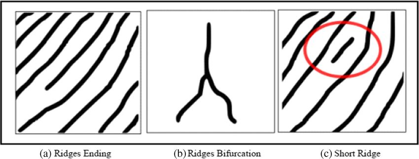
Multimed Tools Appl

Fig. 2 Minutiae points in fingerprint [16]

obtained fingerprint image in order to upgrade its quality thus make the identification
process easier and more accurate [7].

2.2.5 Binarization

During the binarization step the grayscale fingerprint image is converted into a black and white
binary image. This procedure is carried out by correlating every pixel value to a threshold
value (0.5). If the value of the pixel is lower than the threshold value then the pixel value is
assigned black otherwise it is assigned white. The threshold value mentioned here is the
default threshold for the MATLAB’s ‘im2bw’ function which will be used for the purpose of
binarization in this research. However, it is important to note that other thresholding methods
can also be used such as, Otsu’s method [110]. After the image is binarized, a process known
as thinning is then performed.

2.2.6 Thinning (skeletonization)

Thinning sometimes referred to as skeletonization of the image will reduce the thickness of all
ridge lines to one pixel width. It should be noted that this process is quite important as it allows
for minutiae to be extracted more efficiently and won’t change its location [65]. More on
thinning algorithms can be found here ([44, 69]. A sample fingerprint with its corresponding
thinned skeleton image is shown in Fig. 3.

Fig. 3 A fingerprint with its corresponding binary image and ridge skeleton [32].
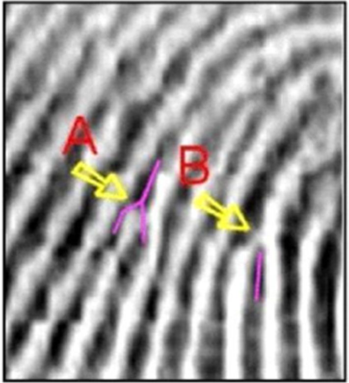
Multimed Tools Appl

2.2.7 Minutia extraction

Only a few matching algorithms operate on grayscale fingerprint images directly, therefore an
intermediate fingerprint likeness must be derived, this is done during a feature extraction
process. A capture device is used to take a distinctive image of the users fingerprint.
Distinctive software is then used to examine the fingerprint image and decides if the image
truly is a fingerprint, by checking the pattern type (e.g. left loop, right arch, etc.),
measuring ridge line qualities, and lastly extracting minutia. Minutiae specify where a
significant change has occurred in the fingerprint [10]. These changes are shown in
Fig. 4. The dark lines in the image show ridges and the light lines show valleys,
Arrow A shows an area where one ridge splits into two (known as a bifurcation) and
Arrow B shows where a ridge ends.
   When these fingerprint features are located, the extraction software establishes a
notable direction of the change (using Arrow B as an example, the notable direction
begins at the end of the ridge and progresses in a descending direction). Simply put,
the resultant minutia is a group of all reasonable bifurcations and ridge endings, their
location, and their specific direction.

2.2.8 Fingerprint matching

Fingerprint matching algorithms work by comparing two given fingerprints and outputs either
a percentage of similarity (usually a score between 0 and 1) or a binary decision (match or no
match). Only a minority of matching algorithms function directly on grayscale fingerprint
images; nearly all of them require that an intermediate fingerprint image be obtained via a
feature extraction process [76–78]. A large amount of fingerprint matching techniques can be
divided into two families: correlation based and minutiae based. Correlation based matching
operates by superimposing two fingerprint images and computes the correlation between
corresponding pixels for various alignments (different displacements and rotations).
Minutiae-based techniques, which seem to be the most popular approach, extract minutiae

Fig. 4 Fingerprint Changes
(fingerprint thesis desktop)
Multimed Tools Appl

from the two fingerprints and essentially match the alignment between the database template
and the minutiae presented by the user shown in Fig. 5.
   This approach is deemed an uncomplicated one. However, the binarization and thinning
process is believed to be time consuming by some [32]. Therefore many researchers have
suggested minutiae extraction techniques that operate precisely on the grayscale images
eliminating the need for these procedures [73]. The general concept these authors focused
on is tracking the ridge lines within the grayscale image to obtain a polygonal approximation
of the ridge line.

2.3 Multibiometric systems

Multibiometric systems identify users by using two or more biometric traits. Research carried
out by Patra [84] shows that multibiometric systems are more secure than unimodal biometric
systems (biometric systems that rely on only one trait) mainly due to the presence of multiple
data. They discuss how a system uses multiple characteristics for authentication purposes and
believe that the use of multiple biometrics makes it much more difficult for an intruder to trick
the system. Furthermore, a system that uses two or more user traits ensures a live user is
present at the time of data acquisition. Multiobiometrics may have improved the security of
biometric systems; however security of multi-biometric templates is especially critical as they
hold user data regarding multiple traits. If any kind of template data was leaked to an
unauthorized person the security and privacy of users may be compromised. [1].
   Even though a biometric system can better accommodate users and boost security, they are
also vulnerable to numerous types of threats [114]. An imposter may gain entry to the system
and browse private data such as medical reports belonging to a genuinely enrolled user.
Besides violating user privacy, the intruder can also alter any sensitive information that they
have accessed. A genuine user may abuse their authentication rights by entering the system,
and maintain that an imposter had done so. For example, a bank employee may alter a
customer’s bank account details and insist that an imposter could have done this by deceiving
the system and stealing the biometric data. An unauthorized user can secretly obtain a user’s
raw biometric information to gain entry to the system. For example, an intruder may collect an
authorized person’s latent fingerprint from a specific item, and in time use the fingerprint to
create a physical or digital representation of the finger, which in many cases can lead to
identity fraud. A biometric user who has access to a wide range of system privileges (i.e.
administrator) may intentionally alter system parameters to enable an intruder to attack the

Fig. 5 Matching minutiae points in two fingerprints [16]
Multimed Tools Appl

system, allowing the intruder to view, change or even steal the biometric data that is stored on
the system. An attacker may overload system resources so that genuine users wishing to enter
will be denied any service. For instance, a server that deals with access applications can be
submerged with an extensive amount of fake requests, thus overloading its data processing
resources which would prevent legitimate requests from being processed.
   In this section the functionalities of biometric systems were discussed. Various
biometric techniques along with their strengths and weaknesses were examined.
Fingerprint biometrics was discussed in detail and various feature extraction methods
were explored. The weaknesses of biometric systems in regards to security and
privacy were also highlighted. Research shows that even though the use of biometrics
can boost user accessibility, they are also susceptible to numerous types of attacks.
So, in order to enhance the security of these systems, primarily fingerprints, the field
of digital steganography will be explored and tested.

3 Steganography

Steganography can be described as the art and science of covert communications
which involves the process of hiding information inside other information. Unlike
cryptography, steganography messages do not draw attention to themselves, as data is
hidden in such a way as to make it undetectable to the human eye. The word
steganography is derived from the Greek words Bstegos^ meaning Bcover^ and
Bgrafia^ meaning Bwriting^, defining it as Bcovered writing^. This practice and idea
of hiding information can be traced back as far as 440 BC and has been used in
many forms over the years [12].
   According to Greek historian Herodotus, Histaiacus, a Greek tyrant, used a form of
steganography to communicate with his son-in-law Aristagoras. Histaiacus shaved the
head of a trusted slave and tattooed a secret message on to his scalp. Once the slave’s
hair grew back he was sent to Aristagoras with the hidden message [19]. Another form
of steganography occurred in World War 2 when the Germans developed the microdot
technique. This method allowed for a lot of information, mostly photographs, to be
condensed to the size of a typed period. Information was then hidden in one of the
periods on the paper (i.e. a full stop) and distributed over an unprotected channel. The
FBI detective, J. Edgar Hoover described the use of microdots as Bthe enemy’s
masterpiece of espionage^ [25]. Although steganography has been in existence for
many years, its current formation can be explained using the Prisoners’ problem
proposed by Simmons [81] where two inmates wish to secretly exchange information
to come up with an escape plan. All communication between the two inmates has to
pass through a warden. If the warden suspects any type of covert communication has
taken place, both inmates will be sent to solitary confinement. All correspondence
between the inmates can be checked by the warden, the warden can be either passive or
active. If the warden takes a passive approach he\she will attempt to detect if the
communication contains any secret information. If covert communication is discovered
the warden will make note of it and inform an outside party, information will be
allowed to pass through without obstruction. However, if an active warden suspects
any hidden information, he/she will attempt to modify the communication by removing
or altering the hidden data.
Multimed Tools Appl

3.1 Steganographic conditions

For a steganographic algorithm to be successful it must adhere to the following
requirements: [81]

&   Invisibility: first and foremost, a steganographic technique needs to be invisible, consid-
    ering the aim of steganography is to fend off unwanted attention to the transmission of
    hidden information. If the human eye suspects that information is hidden then this goal is
    defeated. Moreover, the concealed data may be compromised.
&   Payload capacity – Dissimilar to the watermarking method of information hiding where
    only a small amount of copyright data needs to be embedded, steganography aims at
    covert communication, thus requires adequate embedding space.
&   Robustness against statistical attacks – Statistical steganalysis is the technique used to
    discover if hidden information exists. A steganalyst will examine image data by carrying
    out various statistical tests. Many steganographic algorithms leave a ‘signature’ when
    embedding information that can be easily detected through statistical analysis.
    (Steganalysis will be discussed in more detail in section 5)
&   Robustness against image manipulation – During the course of the communication
    process an image can be subjected to changes by an active warden in an effort to expel
    secret information. Prior to the image reaching its destination it can be manipulated by
    using techniques such as rotating or cropping. Depending on how the information is
    embedded, these manipulations may sabotage or ruin any hidden data. A Steganography
    algorithm is more preferable if it is potent against malicious or unforeseen adjustments to
    the image.
&   Independent of file format – As there are an abundance of various image file formats
    being used on the web, it may attract unwanted suspicion that an individual type
    of file format is repeatedly communicated amongst two parties. However, if a
    stenographic algorithm is powerful it should possess the ability to embed data in
    all types of file formats. This requirement also sorts out the issue of not always
    being able to acquire a suited image at the correct moment in time, that is, the
    correct format to use as a cover image.
&   Unsuspicious files – This requirement contains all features of a stenographic algorithm that
    may consist of images that are not commonly used and can lead to suspicion. For example,
    file size that are abnormal may attract suspicion, thus result in further examination of the
    image by a warden.

   An essential condition of a steganographic system is that the image being used (stego-
image) for steganography purposes must be as close as possible to the original image, as not to
raise suspicion or attract any unwanted attention to the stego image. Image embedding
capacity and data invisibility are two primary requirements that have been extensively
researched in different steganography techniques over the years [55, 56].
   In 1999 [57] presented a thorough survey on ‘Information Hiding’. Steganographic
methods in use today have progressed a lot since then. In 2006 [8] produced a paper
which examined various spatial domain techniques using the least significant bit
approach, applied to the GIF image format. Goel and colleagues presented a more
recent study on image steganography techniques, published in 2013 [43].
Multimed Tools Appl
3.2 Digital image steganography
Due to the expansion of the World Wide Web there has been a noticeable increase in the use of
digital images. The large quantity of redundant bits that exist within a digital image represen-
tation, makes images more preferable for embedding steganographic data. An abundance of
diverse image file formats exist within the digital image domain. For each of these different
image formats, various steganographic techniques exist [81]. As mentioned earlier, steganog-
raphy can be implemented using reversible and irreversible techniques. Prior to exploring these
techniques, it is necessary to gain an understanding of digital images.
A PC presents images as an assortment of binary digits, comprising distinctive light
intensities, in the various image sections [81]. This digit representation constructs a grid.
The various locations on the grid are known as pixels. Generally, most digital images on the
web are made up of a rectangular graph consisting of images pixels, (bits) where each pixel’s
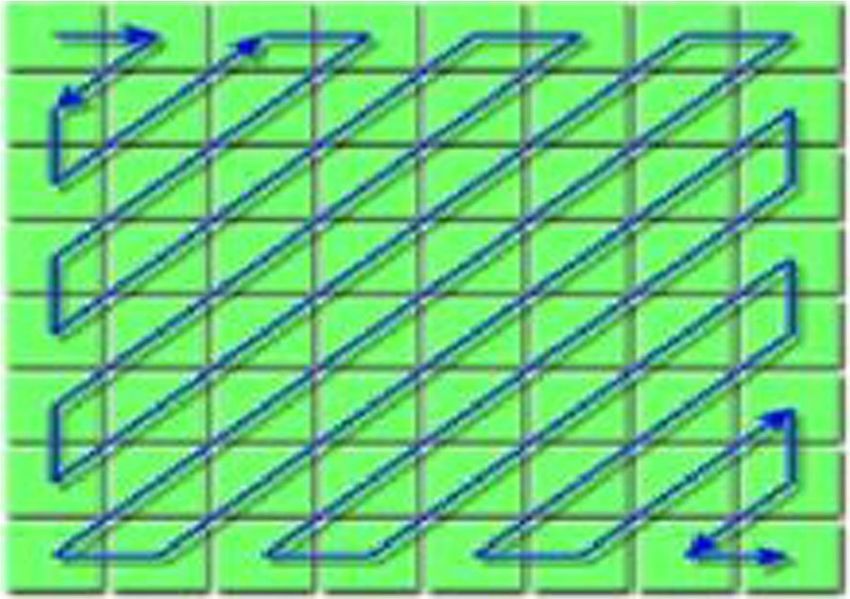
colour is contained. These pixels are presented on the grid horizontally, row by row. The bit
depth, which also can be explained as the total number of bits in a colour scheme, relate to the
total amount of bits used for individual pixels. In Greyscale or Monochrome images, each
pixel uses 8 bits and is capable of displaying 256 various colours or shades of grey. Digital
images that are coloured normally contain 24-bit files and use the RGB colour model. The bit
depth of modern colour schemes is 8; this means that 8 bits are needed to represent the colour
of each pixel. All colour variations for pixels of a 24-bit image derive from three colours: red,
green and blue, and all colours are represented by 8 bits. Therefore, in one pixel, there can be
256 specific amounts of red, green and blue, producing more than 16-million colours. In
addition, the more colours displayed, the larger the image file will be [66].
To transmit an image over the internet successfully it must be an appropriate size. In some
cases, (minimum storage, system performance) larger images may not be appropriate, smaller
images may be preferred. In certain circumstances, mathematical formulas can be used to
decrease the size of the image by condensing the image data, consequently reducing the image
size. This technique is known as compression, which can be either lossy or lossless. Both
approaches compress the image to save on storage, but are implemented quite differently [13].
The lossy compression technique decreases the file size by eliminating redundant bits of data
from the original image. It eliminates areas of the image that are not visible to the human eye;
as a result some data may be lost. Although the compressed image bears a close resemblance to
the original image, the compressed image is not an exact duplicate, mainly due to data
elimination. An example of an image format that uses lossy compression is JPEG (Joint
Photographic Experts Group). The JPEG file format will be discussed in detail in the next
section [67]. In contrast, lossless compression does not discard any data from the original
image. After compression, all original data is restored. This technique would generally be used
for spread sheets or text files where loss of data would cause problems. The down-side of this
technique is the larger image size. Image formats such as Bitmap, PNG and GIF use lossless
file compression [18].
Unlike other information hiding techniques, the main goal of steganography is to ensure
that any hidden data is invisible to the human eye. As discussed above, there are many
requirements that a steganographic algorithm must satisfy to ensure the secrecy of hidden
information. The use of digital images and image compression plays a significant part in
choosing which steganographic algorithm to use. For example, lossy compression methods
(relating to JPEG images) provide smaller image file sizes, but it intensifies the probability of
the hidden information being altered or lost based on the fact that some redundant data isMultimed Tools Appl
always eliminated. Lossless compression (relating to GIF, PNG images) allows for an image to
be compressed without any loss of data, allowing the original image to be maintained. As a
result of the lossless approach the image will be larger in size. Lossless image formats may not
be suitable for hiding biometric data, as biometric systems also require a fast response time as
well as strong security measures [103]. The reversible data hiding technique is another
approach to lossless data hiding [100]. Reversible algorithms are often implemented to
preserve sensitive images such as medical, government or military imagery. For images like
these, even the slightest distortion caused by data embedding is unacceptable [108]. For
example, a medical related image such as an x-ray, even a minor change to the image may
lead to misinterpretation by a medical practitioner. Hence, why a reversible hiding technique
would be a more appropriate approach in this case. Many steganographic algorithms have been
developed for both of the above compression techniques and will be explained in detail in the
next section.
4 Data hiding in digital images
Two of the most popular digital image formats relating to internet usage are Joint Photographic
Experts Group (JPEG) and Portable Network Graphics (PNG). Other image formats are also
used, such as Graphics Interchange Format (GIF), but to a lesser degree. Most of the
steganographic techniques created were constructed to manipulate the design of the image
formats mentioned [21].
Embedding information using steganography can be carried out by inserting the following
line of code into a Microsoft command window:
C : n > Copy Cover:jpg=b þ Message:txt=b Stego:jpg
The above code appends the hidden information found in the text file ‘Message.txt’
inside the JPEG image file ‘Cover.jpg’ and constructs the stego-image ‘Stego.jpg’. The
concept behind this is to exploit the recognition of EOF (End of file), that is, the
information is loaded and added after the EOF tag. When observation of the Stego.jpg
occurs using any image editing tool, the latter simply exhibits the image disregarding
anything that follows the EOF tag. However, if opened in Notepad, the hidden data will
be unveiled. The embedded data does not decrease the quality of the image. Image
histograms or visual perception will identify any disparity between the two images as the
secret data is hidden after the EOF tag. Although this technique is easy to implement,
many steganography programs distributed on the internet make use of it (Camouflage,
JpegX). Unfortunately, this simple procedure would not withstand any type of altering to
the Stego-image nor would it endure steganalysis attacks [90]. Another straightforward
method is to affix secret data to the Extended File Information of the image, this is a
common approach taken by the manufacturers of digital cameras to store metadata info
in the image header file, and i.e. the cameras make and model. However, this technique
is just as unreliable as the preceding approach as it is very simple to overwrite such
information [20]. In recent years, data hiding, using the LSB embedding method within
the spatial domain (pixel level) of images was a very popular technique. This was mainly
due to its potentially sizable capacity and its simplicity. More recent studies investigated
the frequency domain [12, 46, 104].Multimed Tools Appl
Steganography methods can generally be restricted to Spatial Domain, Frequency Domain
and Hybrid Techniques.
4.1 Spatial domain techniques
Least significant bit (LSB) replacement is a typical, straightforward procedure for inserting
information into a cover image [42]. During this process, the LSB within the cover medium
can be overwritten with the binary representation of the secret data. In the case of using a 24-
bit colour image individual components are capable of storing 1 bit of d'ata in its LSB. For an
example, take the 3 neighbouring pixels (9 bytes) below:
ð00101101 00011100 11011100Þ
ð10100110 11000100 00001100Þ
ð11010010 10101101 01100011Þ
First off, the binary representation 11,001,000 (200), is inserted into the least significant bits of
this section of the image; the resulting grid is then as follows:
ð00101101 0001110 1 11011100Þ
ð10100110 1100010 1 00001100Þ
ð11010010 1010110 0 01100011Þ
The binary number was embedded into the first 8 bytes of the grid. However, only 3 existing
bits had to be modified (bits are denoted with underline) for the required data to be embedded.
Considering there are potentially 256 intensities of each primary colour, modifying the LSB of
a pixel results in tiny changes in the intensity of the colours. These changes cannot be
recognised by the human eye thus, data hiding the data is accomplished [85].
However, this procedure is especially easy to identify. For example, an attacker
looking for uncommon patterns or using various attack techniques (discussed in the
next chapter), can quite easily detect any occurrence of hidden information [47].
Additionally, LSB makes use of BMP images, as they use lossless compression. To
hide concealed information inside a BMP file would require the cover image to be
extremely large. Moreover, BMP images are not often used on the internet and may
attract suspicion. For this reason, LSB steganography has also been developed for use
with other image file formats [81].
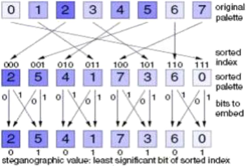
Palette based images, for example Portable Network Graphics (PNG) or Graphics Inter-
change Format (GIF) images are another common image file format used on the Internet. In
recent years, the PNG, format has replaced the older GIF format [127]. Palette based images
consist of an index and a palette. The index contains information indicating where each colour
is positioned in the palette. It also contains all the colours used in the image and each colour in
the palette corresponds to various colour components [81]. Palette based images may also be
used for LSB steganography. According to (Johnson) extra care should be taken if making use
of this type of format. One issue with the palette approach used with GIF images is that if the
least significant bit of a pixel is changed, it may result in creation of, or pointing to an entirely
different colour as the index to the colour palette is changed If neighbouring palette entries are
alike, there will be no distinct change, but if the neighbouring palette entries are different, the
change would be obvious to the human eye [55, 56]. A solution to this problem is to sort the
palette so that the colour differences between consecutive colours are reduced [17]. Another
solution to this problem would be to use greyscale images for embedding data. An 8-bitMultimed Tools Appl
greyscale image contains 256 variants of grey thus any changes to the palette may be less
noticeable therefore secret data may be harder to detect [55, 56].
Gupta et al. [47] proposed a technique using LSB method by embedding encrypted
information into the image in place of plain textual data. The overall process is more complex
and time consuming. However, the security of hidden data did improve. [61] also proposed an
algorithm to enhance the security of LSB embedding. This embedding procedure also involves
an encryption phase. The process involves embedding the secret data into the image using
BLeast Significant Bit algorithm^ by which the least significant bits of the secret document are
organized with the bits of a carrier file (digital image). The idea is to merge the message bits
with the bits of carrier file. Results show that the proposed approach does improve security and
protect secret data from attacks, as data is encrypted and only an authorized person that is
aware of the encryption can access the secret information. Tests carried out showed little
change to the image resolution and after data was embedded only slight changes occurred in
the stego image.
4.2 Pixel value differencing
Another well-known technique used for data hiding in the spatial domain is Pixel Value
Differencing [71, 117, 124]. PVD works by calculating the difference between two
neighbouring pixels. If the difference output between the two pixels is a large value, then this
indicates that the two successive pixels are edge pixels. If the difference value is small, then
successive pixels belong to a smooth area of the image. The PVD approach was first
introduced by [124] and results showed less distortion to the image when compared with
other LSB algorithms. However, this technique does not come without limitation. For exam-
ple, if the calculated original difference is not equal to the secret data then adjustments need to
be made to the two successive pixels, which in turn, may cause much distortion to the stego-
image. Wang et al. [117] introduced a method to minimise image distortion by using the
modulus function. The modulus function was used to alter the carry-over of the difference
between the two successive pixels instead of making an adjudgment to the difference value. In
terms of image quality, [117] method showed much better results than the preceding approach
implemented by [124].
In a more recent study, [59] proposed a new reversible data hiding technique based on the
sorting and prediction of digital images. This proposed technique embeds two bits in a 3 × 1
sub-block at maximum by division of two groups, min and max groups. This method works by
firstly predicting the pixel pairs of both the min and max groups. The secret data is
then hidden within these predicted pixels. Jung states that reversibility is guaranteed
as the order of pixel pairs of the sub-blocks are not changed after embedding secret
bits into the to groups. Results showed that the proposed method provides a higher
embedding capacity than earlier techniques.
4.3 Transform domain techniques
The following methods attempt to conceal information in the transform domain coefficients of
an image. Data embedding in the transform domain is a popular procedure used for robust data
hiding. Methods can also realize large-capacity embedding for steganography [46]. According
to Goel [42] embedding in the transform domain allows the hidden data to reside in more
robust locations, scattered over the entire image. Furthermore, the above techniques alsoMultimed Tools Appl provide greater protection against many types of image processing and steganalysis attacks [86]. To gain an understanding of the above transform domain methods one must firstly describe the sort of file format associated with this domain (JPEG file format). The JPEG file format is the most favoured file format used for data transmission, mainly because of its condensed image size [27]. For an image to be compressed into JPEG format, first the RGB colour model must be transformed to a YUV representation. A description of the YUV is as follows: (Y) conforms to the luminance (brightness) of the image, both (U) and (V) conforms to the chrominance (colour). Based on research, the human eye is more delicate to adjustments in the luminance of a pixel than to adjustments to any chrominance. The JPEG compression manipulates this fact by downsizing the colour statistics to decrease the capacity of the file. The colour elements (U) and (V) are split in two in horizontal and vertical ways, hence reducing the size of the file by a component of 2 [26]. The next step is the transformation of the image using the Discrete Cosine Transform. 4.3.1 Discrete cosine transform When the DCT is applied, the image is divided into parts of differing priorities. It transforms the image from the spatial domain to the frequency domain [43]. This is achieved by organizing image pixels into 8 × 8 blocks and converting the blocks into 64 DCT coefficients. Any adjustment made to a single DCT will alter all 64 pixels within that block [20]. Figure 6 illustrates an example of the application of the DCT to an image and the effects it has on the given image. The left side of the above figure is an 8 × 8 block of image data. Which can be either luminance or chrominance data. The image on the right is the result after the DCT is applied to this block of the image. Notice how the bigger value is positioned in the top-left corner of the block, this is the lowest frequency. The reason this value is very high is because it has been encoded by DCT and the highest priority contains all image energy. Note how all values nearer to the bottom right hand corner are closer to zero, this is because these values contain less energy. These values are classed as the high frequencies; it is these frequencies that will be discarded during the next process [13]. When the image has been transformed quantization is the next stage of the process. During this stage the human eye again is exploited. As discussed earlier the human eye can be Fig. 6 Pixel Values vs DCT coefficients [13]
Multimed Tools Appl

sensitive to certain areas of an image. For example, our eyes are relatively good at recognising
tiny changes in luminance (brightness) over a relatively large area, however, not so great at
recognising various strengths in high frequency brightness. This allows the strength of higher
frequencies to be reduced, without modifying the presentation of the image [81] For example,
consider an image with a dense collection of trees, in which you have an all-around view.
Smaller trees that you don’t notice may exist beneath the larger trees in the image. If you
cannot see these trees, your view will not be affected if the small trees are there or not.
Quantization can be viewed as exactly the same principle. JPEG carries out this process by
separating all the values in a block by a quantization coefficient. The outcome is rounded to
integer values [13].
   The quantised coefficients of the DCT shown above in Fig. 7 are typically normal. There
are only a slight amount of individual values where the numbers are larger than zero (most will
always be zeros). It is also common practice that all non-zero numbers reside towards the
upper left, and zeros to the lower-right corner. Due to the fore mentioned, another process must
be applied to group similar frequencies together; this process is called zigzagging. The purpose
of this procedure is to group all low frequencies together using a zigzag motion. As stated
above, after quantization there will only be a minimal amount of values that hold
values (low frequencies) other than zeros (high frequencies), the zig-zag process
works by re ordering these values so that related frequencies are brought together.
This will allow for high compression to be achieved [13]. See Fig. 8. The final stage
uses an algorithm such as Huffman coding to compress the image and Huffman trees
are stored in the JPEG header [96].

4.3.2 JPEG steganography

According to [63] it was originally the belief that steganography might not be feasible to
use with JPEG images, the reason being, that JPEG’s usage of lossy compression. As
discussed previously, steganography can make use of redundant bits in an image to
embed hidden data, considering redundant bits are omitted in JPEG it was feared that any
hidden information would be lost. Moreover, if the hidden information came through
unharmed, it may, be equally as challenging to embed information without any adjust-
ments being obvious, due to the severe compression that is used. Nonetheless, attributes
of the compression algorithm have been taken advantage of to create a steganographic
algorithm for JPEG images labelling the algorithm as being lossy, this attribute too can
be used to conceal hidden information [68]. The main advantage DCT has over alterna-
tive transforms is its capability to decrease the block-like presentation resulting when the
boundaries between the 8 × 8 sub-images become apparent. A disadvantage of DCT
being that it only can operate on JPEG files as it presumes a certain numerical

Fig. 7 Quantisation procedure [13]
Multimed Tools Appl

Fig. 8 The Zigzag grouping process [13]

arrangement of the cover data that is generally established in JPEG files. A few common
DCT based information hiding techniques are JSteg, F5 and OutGuess [14]. Yet Another
Steganographic Scheme (YASS) is an additional method related to JPEG steganography
[106].

4.3.3 Discrete wavelet transform

Recently, the Discrete Wavelet Transform (DWT) has proved to be the preferred area of study
in the field of information hiding [46, 93, 99]. This is mainly due to its extensive utilization in
the new image compression standard, JPEG2000 [41], and its ability to address capacity and
robustness [6]. Unlike the DCT procedure, DWT provides frequency, along with spatial
description of an image. For example, if the signal is embedded, it will affect the image in a
local way. Wavelet transform is believed to be more applicable to data hiding as it divides
high-frequency and low-frequency information based on the pixel-by-pixel basis [20]. The
DWT divides pixel values into various frequency bands known as sub bands. Each sub band
can be described as the following: [12].

&   LL – Horizontally and vertically low pass
&   LH – Horizontally low pass and vertically high pass
&   HL - Horizontally high pass and vertically low pass
&   HH - Horizontally and vertically high pass

   As mentioned previously the human eyes are much more sensitive to certain areas
of an image such as low frequency bands (LL sub- band). This enables information to
be hidden in the other three sub bands without any alterations being carried out in the
LL sub-band. Each of the other three sub-bands contains irrelevant information as
they are high frequency sub-bands. In addition, embedding private information within
these sub-bands will not have a big effect on degrading image quality [104]. To gain
a better understanding as to how wavelets work the 2-D Haar wavelets will be
discussed. A 2-dimensional Haar-DWT consists of two operations, a horizontal and
a vertical one. Operation of a 2-D Haar [22] is as follows:
Multimed Tools Appl

Step 1:     First, the pixels are scanned from left to right, horizontally. Next, the addition and
            subtraction operations are carried out on adjacent pixels. Then, the sum is stored on
            the left and the difference stored on the right as shown in Fig. 9. The above process
            is repeated until all the rows are processed. The pixel values sums represent the low
            frequency element (denoted as symbol L) while the pixel differences represent the
            high frequency elements of the original image (denoted as symbol H).
Step 2:      All pixels are scanned from top to bottom in vertical order. Next, addition and
             subtraction operations are carried out on adjacent pixels, the sum is then stored on
             the top and the difference is stored on the bottom as shown in Fig. 10. Again, the
             above process is repeated until all columns are processed. Lastly, we will be left
             with 4 sub-bands denoted as LL, HL, LH, and HH. Note, the LL sub-band is the
             low frequency section therefore looks almost identical to the initial image.

   The entire process explained above is called the first-order 2-D Haar-DWT. The effects of
applying first-order 2-D Haar-DWT on the image BLena^ is shown in Fig. 11.
   In comparison to DCT, recent studies have shown that wavelets are considered as being less
resource intensive and cause less distortion to an image hence why the DWT method is
becoming a more popular. Moreover, as DWT is broken down into sub-bands, it gives higher
flexibility in terms of scalability [31].

4.3.4 Hiding biometric data

Shejul and Kulkarni [104] propose a steganography method based on biometrics. The bio-
metric feature used to implement steganography is the skin tone region of images. The
technique suggested involves embedded data in skin region of images. Prior to embedding,
the skin tone detection is carried out using HSV (Hue, Saturation and Value) colour space.
Additionally, data embedding is implemented using frequency domain approach - DWT
(Discrete Wavelet Transform). Secret data is embedded in one of the high frequency sub-
bands of DWT by tracing skin pixels in that sub-band. Their analysis shows that by adopting
an adaptive technique, in the sense that, skin tone objects are traced in image by cropping
various image regions to embed that data, enhanced security is achievable. A skin tone
detection steganography algorithm is proposed by [20], which demonstrates robustness to
attacks, while keeping the secret data invisible, by embedding in skin regions of an image. This
technique is very appropriate for hiding biometric data, especially where templates contain a
lot of skin attributes (i.e. facial or fingerprints).

Fig. 9 The horizontal procedure based on the first row [22]
You can also read