Arbitrary Waveform Generators - AWG70000B Series
←
→
Page content transcription
If your browser does not render page correctly, please read the page content below
Arbitrary Waveform Generators
AWG70000B Series
                                                                                        Synchronize multiple units (manually or with the AWG Synchronization
                                                                                        Hub) to achieve a multi-channel high speed AWG system
                                                                                        Fully operational without external PC
                                                                                            Built-in display and buttons make it possible to quickly select, edit
                                                                                            and play waveforms directly from the front panel of the AWG
                                                                                        Simulate real-world environments by playing back captured signals
                                                                                            Waveforms captured with Oscilloscopes or Real-Time Spectrum
                                                                                            Analyzers can be played back, edited or re-sampled on the AWG
                                                                                        Smooth transition from simulation to the real-world testing environment
                                                                                            Waveform vectors imported from third-party tools such as MATLAB
                                                                                        Sequencer with Streaming ID
                                                                                            Control the Sequencer directly via a network interface connection
The AWG70000B Series arbitrary waveform generators (AWG) represent
the cutting edge for sample rate, signal fidelity, and waveform memory,             Applications
making them ideal for design, testing, and operations of complex
components, systems and experiments. With up to 50 GS/s and 10-bit                      Wideband RF/MW for communications and defense electronics
vertical resolution, it delivers the industry's best signal stimulus solution for           Output wideband RF signals up to 20 GHz
easy generation of ideal, distorted, and "real-life" signals.
                                                                                        Validation and compliance testing of high speed silicon and
                                                                                        communications devices
Key performance specifications
                                                                                            Easily stress test receivers with a wide array of signal impairments
    Sample rates up to 50 GS/s
                                                                                        Coherent optical research
    -80 dBc spurious free dynamic range                                                     Generation of high Baud rate baseband signals with higher order,
    10 bits vertical resolution                                                             complex modulation
    Waveform memory of up to 32 GSamples                                                Leading edge research in electronics, physics & chemistry
                                                                                            High speed, low jitter signal source generates uniquely specified
Key features                                                                                analog signals, fast pulses, data streams and clocks

    Complete solution for wideband RF signal generation in a single box
                                                                                    Performance you can count on
         Direct generation of wideband signals with carriers up to 20 GHz,
         removing the need for external RF conversion                               Depend on Tektronix to provide you with performance you can count on. In
                                                                                    addition to industry-leading service and support, this product comes backed
    Simulate real-world analog effects on high speed digital data streams           by a standard one-year warranty.
         Model signal impairments up to speeds of 12.5 GB/s
    Generate high precision RF signals
         Spurious Free Dynamic Range performance better than -80 dBc
    Create high speed baseband signals for optical transmission with the
    vertical resolution to handle higher order complex modulation
         10 bits of vertical resolution at a sample rate of 50 GS/s
    Create long waveforms scenarios without building complex sequences
         Up to 32 GSamples of Waveform Memory plays 640 ms of data at
         50 GS/s

                                                                                                                                                www.tek.com 1
Datasheet

Seamless transition from simulation to                                           The latest digital RF technologies often exceed the capabilities of other test
generation                                                                       instruments because of the need to generate the wide-bandwidth and fast-
                                                                                 changing signals that are increasingly seen in many RF applications such
If a waveform can be defined or captured, then the AWG70000B can
                                                                                 as Radar, RF communications, OFDM, and Multi-tone. When used in
generate the signal. The creation of the waveform can happen in many
                                                                                 conjunction with the specific plugin, the AWG70000B Series supports a
ways. Waveform creation plug-ins, which are optimized to work specifically
                                                                                 wide range of modulation formats and simplifies the task of creating
the Tektronix AWG family, provide specific waveform creation capabilities,
                                                                                 complex RF waveforms. The AWG70000B Series instruments provide
while 3rd party solutions like MATLAB, Excel, or others, have the flexibility
                                                                                 customers with ways to generate fully modulated baseband, intermediate
to create any waveform you desire. Waveforms created in any of these
                                                                                 frequency (IF) signals, or directly generated RF waveforms up to 20 GHz.
packages can be imported and played back in the AWG70000B,
seamlessly transitioning from the simulation world to the real world.
Additionally, any signals captured on Tektronix oscilloscopes or Real-Time
Spectrum analyzers can be loaded into the AWG70000B and played back.
With the use of the built in waveform generation plug-ins, the captured
signal can also be modified or changed to meet any specific requirements
that may exist.

Wideband RF signal generation
RF signals are becoming more and more complex, making it more difficult
to accurately create the signals required for the testing and characterization
of RF systems. To address these challenges, RF Generic delivers
advanced capabilities to synthesize digitally modulated baseband, IF and
RF/microwave signals supporting a wide range of modulation schemes.
The RF Generic, Radar, Multitone, OFDM, and Environment plug-in's easy
to use graphical user interfaces integrate seamlessly with the AWG70000B
Series user interface or the SourceXpress remote PC application.                 3 GHz wide multi-carrier signal generated on the AWG70000B with over 60 dBC SFDR

                                                                                 Radar signal creation
                                                                                 Generating advanced radar signals often demands exceptional
                                                                                 performance from an AWG in terms of sample rate, dynamic range, and
                                                                                 memory. The Tektronix AWG70000B Series sets a new industry standard
                                                                                 for advanced radar signal generation, by delivering wide modulation
                                                                                 bandwidths up to 20 GHz. With a sample rate of up to 50 GS/s, the
                                                                                 AWG70000B Series can directly generate RF signals never before possible
                                                                                 from an AWG. In instances where IQ generation is desired, the
                                                                                 AWG70000B offers the ability to oversample the signal, thereby improving
                                                                                 signal quality with its outstanding SFDR performance.
                                                                                 The AWG70000B and the Radar plug-in are the perfect solution for creating
                                                                                 complex radar signals. Users get the ultimate flexibility in creating custom
                                                                                 radar pulse suites. Modulation types such as LFM, Barker and Polyphase
                                                                                 Codes, Step FM, and Nonlinear FM are easily created using the AWG, and
                                                                                 the flexibility of the plug-in enables the creation of waveforms requiring
                                                                                 customer-defined modulation. The combination AWG and Radar plug-in
                                                                                 solution also has the ability to generate pulse trains with staggered PRI to
                                                                                 resolve range and doppler ambiguity, frequency hopping for Electronic
                                                                                 Counter-Counter Measures (ECCM), and pulse-to-pulse amplitude variation
The AWG70000B with the RF Generic Plugin allows complex RF Waveform Generation   to simulate Swerling target models including antenna scan patterns, clutter,
                                                                                 and multipath effects.

2 www.tek.com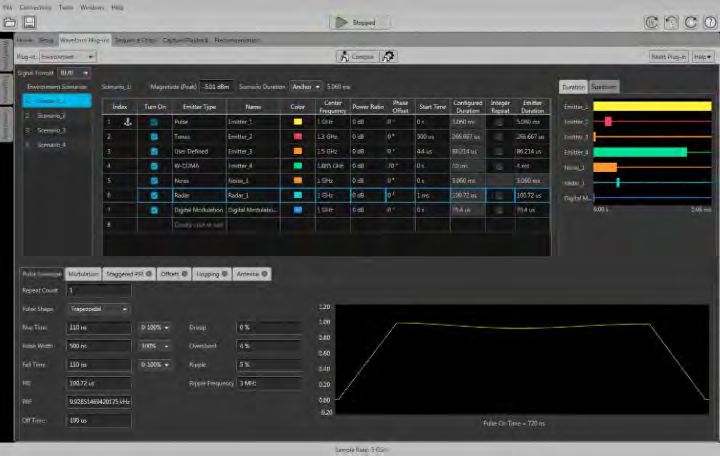
AWG70000B Series Arbitrary Waveform Generators

                                                                                Multiple scenarios with multiple emitters using the Environment plug-in

                                                                                Coherent optical
                                                                                Today's high speed and increasingly web driven world is pushing the
                                                                                demand for short and long haul coherent optical development. Phase
AWG radar pulses created with AWG70000B and Radar plug-in
                                                                                modulation, high baud rate, high sample rate, bandwidth and resolution are
                                                                                all critical to optical applications. Tektronix understands the challenges and
                                                                                inconsistencies of coherent optical testing and offers a reliable, easy to set
Environment signal generation                                                   up and high performing tool set for optical testing, waveform generation and
                                                                                calibration.
The mission-critical nature of many radar signals requires that they coexist
with standards-based commercial signals sharing the same spectrum               The Tektronix AWG70000B Series Arbitrary Waveform Generator (AWG)
without performance degradation. To meet this expectation, a radar              can reach sampling rates as high as 50 GS/s with 10 bits vertical
designer has to thoroughly test all the corner cases at the design/debug        resolution. Such level of performance allows for the direct generation of IQ
stage. The AWG70000B and the Environment plug-in offers extreme                 basebands signals required by modern coherent optical communication
flexibility to define and create these worst-case scenarios.                    systems based on quadrature modulation of an optical carrier with data
                                                                                rates well over 200Gb/s. Multiple AWG70000Bs can be synchronized
You can specify up to 50 scenarios to define your environment, including        (manually or with the AWG Synchronization Hub) to use the max 50 GS/s
WiMAX, WiFi, GSM, CDMA, W-CDMA, DVB-T, Noise, Bluetooth, LTE,                   on each baseband signal with low EVM and 32 Gbaud performance.
OFDM, Radar and more. This plug-in also allows you to seamlessly import
signals from other plug-ins (including Radar, RF Generic etc.), as well as      Generating the desired signal is only the first challenge in coherent optical.
from Matlab® and from Tektronix spectrum analyzers and oscilloscopes,           The quality of the signal, low EVM's and having a clear open eye is crucial.
into your environment. You can also configure PHY parameters of your            The Optical plug-in, in conjunction with the pre-compensation plug-in, can
standard-specific signals. You can define the carrier frequency, power, start   be used for calibration of the AWG to the device under test and for
time, and duration for all the signals in your environment, so you have full    precompensation of coherent optical signals.
control over the way these signals interact/interfere with each other.

                                                                                                                                                      www.tek.com 3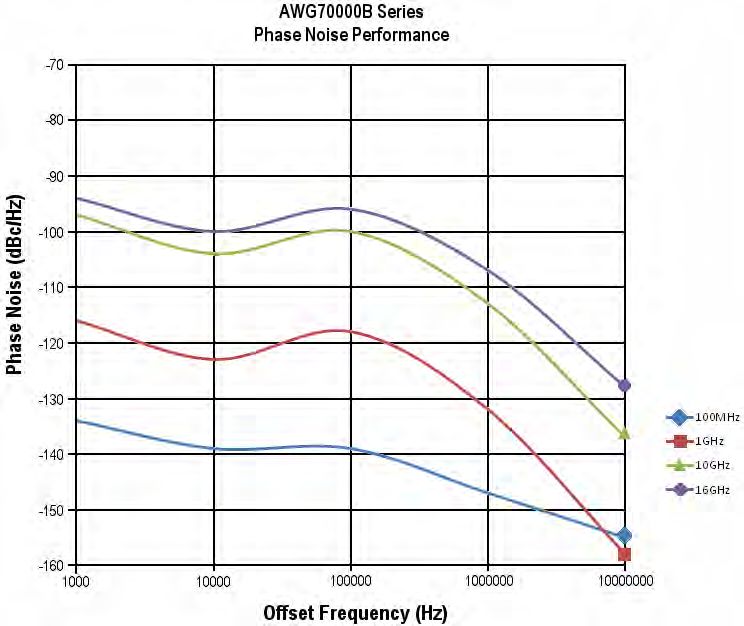
Datasheet

                                                                                  Since the AWG70000B Series is an analog waveform source, it is the
                                                                                  perfect single-box solution used to create digital data streams and mimic
                                                                                  the analog imperfections that occur in real-world environments. The use of
                                                                                  direct synthesis techniques allow engineers to create signals that simulate
                                                                                  the effects of propagation through a transmission line. Rise times, pulse
                                                                                  shapes, delays, and aberrations can all be controlled. When used in
                                                                                  conjunction with the High Speed Serial (HSS) plug-in, engineers are
                                                                                  provided control over every aspect of their digital signals, reaching speeds
                                                                                  of up to 50 Gb/s. This is exactly what is needed for rigorous receiver testing
                                                                                  requirements.

Generic OFDM creation
In today's wireless world, OFDM is becoming the modulation method of
choice for transmitting large amounts of digital data over short and medium
distances. The need for wide bandwidths and multiple carriers create
challenges for engineers who need to create OFDM signals to test their RF
receivers. The AWG70000B Series, when coupled with the OFDM plug-in,              Easily create digital data impairments with the AWG70000B and HSS plug-in
allows users to configure every part of the OFDM signal definition.
Engineers can build signals symbol-by-symbol to create a complete OFDM            The HSS plug-in allows the AWG70000B Series instruments to create a
frame or let the plug-in choose default values for some signal aspects. The       variety of digital data impairments such as jitter (Random, Periodic,
combined AWG and OFDM plug-in supports a variety of data coding                   Sinusoidal), noise, pre/de-emphasis, duty cycle distortion, Inter-symbol
formats that include Reed Solomon, Convolution, and Scrambling. Users             Interference (ISI), Duty Cycle Distortion (DCD), and Spread Spectrum
also have the ability to define each subcarrier in the symbol which can be        Clocking (SSC). The transmission environments of both boards and cables
configured independently for type, modulation, and base data. The OFDM            can be emulated using S-parameter files that can be applied to any
plug-in gives visibility into all aspects of the OFDM signal by providing a       waveform. The AWG70000B and the HSS plug-in also provides base
symbol table that gives a summary of all the carriers in the selected             pattern waveforms for many of today's high-speed serial applications such
symbol. OFDM packets/ frames can be built by specifying the spacing               as SATA, Display Port, SAS, PCI-E, USB, and Fibre Channel.
between the symbols/frames and parts of the OFDM packets can be                   For high-speed serial applications, the AWG70000B Series offers the
stressed by adding gated noise.                                                   industry's best solution for addressing challenging signal stimulus issues
                                                                                  faced by digital designers who need to verify, characterize, and debug
                                                                                  complex digital designs. The file-based architecture uses direct synthesis to
High-speed serial signal generation                                               create complex data streams and provides users with the simplicity,
Serial signals are made up entirely of binary data — simple ones and              repeatability, and flexibility required to solve the toughest signal generation
zeros. As clock rates have increased, these simple ones and zeros have            challenges in high-speed serial communication applications.
begun to look more like analog waveforms because analog events are
embedded in the digital data. The zero rise time and the perfectl flat tops of
textbook digital signals no longer represent reality. Electronic environments
have noise, jitter, crosstalk, distributed reactances, power supply variations,
and other shortcomings. Each takes its toll on the signal. A real-world
digital "square wave" rarely resembles its theoretical counterpart.

4 www.tek.com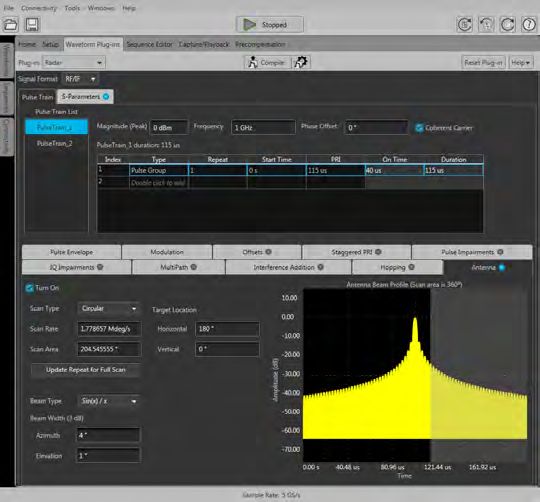
AWG70000B Series Arbitrary Waveform Generators

                                                                                Streaming ID
                                                                                Managing a dynamic reproduction of an RF test environment can
                                                                                sometimes mean keeping track of thousands of individual waveforms. The
                                                                                new Streaming Waveform ID (Streaming WID) option adds a dedicated
                                                                                ethernet port to the rear panel of the instrument. This port allows for direct
                                                                                access to the sequencer hardware via UDP-formatted packets enabling
                                                                                immediate access to over 16000 sequence steps available in system
                                                                                memory. Replicate the chaos of the real world with unprecedented
                                                                                accuracy and accomplish more in less time with Streaming WIDs.

                                                                                Option AC
                                                                                The AWG70001B, with Option AC, provides you with an additional high
                                                                                output amplitude connector. Option AC adds a single-ended AC coupled
                                                                                connector to the front panel of the single channel AWG70001B Arbitrary
                                                                                Waveform Generator. User controls are added to allow switching the output
                                                                                path between the standard Direct output connectors or the AC output
Digital data with de-emphasis added using the AWG70000B and the HSS plug-in
                                                                                connector. When switched to the AC path, additional user controlled
                                                                                amplification and attenuation is added to the signal path.
Create correction coefficients                                                  In AC output mode, you can chose one of the four signal filter paths and set
                                                                                the output amplitude, letting the instrument automatically set the step
Compensate for imperfections in your test setup introduced by cabling,
                                                                                attenuators in the selected filter path. For greater control, you can manually
passive and active RF components and devices to achieve a flat frequency
                                                                                set the attenuation of the step attenuators for your selected filter path.
and linear phase response from your AWG. The Precompensation plug-in
for current Tektronix AWG instruments and the PC SourceXpress software              No filter: -70 to +25 dBm at 1 GHz CW calibration frequency
allows users to compensate for the first and second Nyquist zones of the
AWG. Users can define the LO frequency and choose to get correction                 11.5 GHz Low Pass: -70 to +25 dBm at 1 GHz CW calibration
coefficients for either lower side band or upper side band, as well as define       frequency
the carrier frequency. In all the modes, users can define the bandwidth of          10 GHz - 14.5 GHz Band Pass: -77 to +18 dBm at 11 GHz CW
compensation either by specifying start and end frequencies (RF & IF) or            calibration frequency
bandwidth (in IQ/IQ with modulator).
                                                                                    13 GHz - 18 GHz Band Pass: -90 to +20 dBm at 14 GHz CW
                                                                                    calibration frequency

                                                                                LXI Class C
                                                                                Using the LXI Web Interface, you can connect to the AWG70000B Series
                                                                                through a standard web browser by simply entering the AWG's IP address
                                                                                in the address bar of the browser. The web interface enables viewing of
                                                                                instrument status and configuration, as well as status and modification of
                                                                                network settings. All web interaction conforms to the LXI Class C
The AWG70000B with the Generic Precompensation plug-in
                                                                                specification.

                                                                                                                                             www.tek.com 5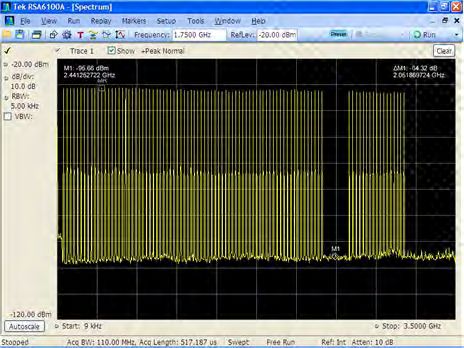
Datasheet

Specifications
All specifications are typical unless noted otherwise. All specifications apply to all models unless noted otherwise.

Model overview
                                                                                    AWG70001B                                       AWG70002B
     Digital to analog converter
           Sample rate                                                              1.5 kS/s - 50 GS/s                              1.5 kS/s - 25 GS/s
           Resolution                                                               10 bit (no markers selected), 9 bit (one marker selected), or 8 bit (two markers selected)
     Number of channels                                                             1                                               2

Hardware characteristics
    Run modes
         Continuous                          Waveform is continuously repeated
         Triggered                           Waveform is output only once after a trigger is received
         Triggered Continuous                Waveform is continuously repeated after a trigger is received

    Waveform memory
         AWG70001B                           Standard: up to 2 GSamples
                                             With extended memory: up to 32 GSamples
         AWG70002B                           Standard: up to 2 GSamples per channel
                                             With extended memory: up to 16 GSamples per channel

    Minimum waveform length
         Triggered run modes                 AWG70001B: 4800 points
                                             AWG70002B: 2400 points
         Continuous run mode                 1 point

    Waveform granularity
         Continuous run mode                 1 point
         Triggered run modes                 AWG70001B: 2 points
                                             AWG70002B: 1 point

    Waveform interleaving
         AWG70001B                           Non-interleaved when ≤ 25GS/s
                                             Interleaved when > 25GS/s
         AWG70002B                           Non-interleaved at all sample rates

    DAC Resolution                           8-bit, 9-bit, or 10-bit

6 www.tek.com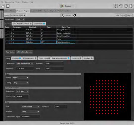
AWG70000B Series Arbitrary Waveform Generators

Analog output characteristics
  Number of channels
      AWG70001B                1 channel
      AWG70001B                2 channels

  Connector type               Aeroflex/Weinschel Planar Crown Universal Connector System with SMA female adapter

  Output impedance             50 Ω

  Effective frequency output   Fmaximum (specified) is determined as "sample rate / oversampling rate" or "SR / 2.5".
      AWG70001B                20 GHz
      AWG70002B                10 GHz

  Bandwidth                    Measured with a multi-sine waveform with equal amplitude across the band. The Sin(x)/x response is mathematically removed
                               from the measured response before recording the -3 dB crossing.
      AWG70001B                15 GHz
      AWG70002B                13.5 GHz

  Output amplitude             Amplitude levels are measured between differential outputs (+) to (-). For single-ended output, the amplitude level will be one-half
                               the specified voltage levels.
      Range                    500 mVp-p to 1 Vp-p
      Resolution               1.0 mV
      Accuracy                 ±(2% of amplitude + 1 mV)

  Rise/fall time               Rise/fall time measured at 20% to 80% levels, related by a factor of 0.75 to the industry standard of 10% to 90% levels.
      AWG70001B                Sampling rate ≤ 25 GS/s: < 23 ps
                               Sampling rate at 50 GS/s: < 27 ps
      AWG70002B                < 22 ps

  Serial data bit rate         Bit rate determined as "sample rate / 4 points per cycle", allowing full impairment generation.
      AWG70001B                12.5 Gb/s
      AWG70002B                6.25 Gb/s

  Output flatness
      AWG70001B                ±1.8 dB up to 10 GHz,
                               +1.8 dB to -3 dB from 10 GHz to 15 GHz
      AWG70002B                +0.8 dB to -1.5 dB up to 10 GHz

  Output match, SWR
      AWG70001B                DC to 5 GHz = 1.32:1
                               5 GHz to 10 GHz = 1.52:1
                               10 GHz to 20 GHz = 1.73:1
      AWG70002B                DC to 10 GHz = 1.61:1

                                                                                                                                                 www.tek.com 7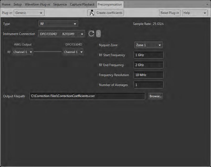
Datasheet

Analog output characteristics
   Frequency response
      AWG70001B             AWG70001B frequency response at 50 GS/s with Sin(x)/x response mathematically removed from measured data.

                            AWG70001B measured frequency response and ideal Sin(x)/x response at 50 GS/s.

      AWG70002B             AWG70002B frequency response at 25 GS/s with Sin(x)/x response mathematically removed from measured data.

                            AWG70002B measured frequency response and ideal Sin(x)/x response at 25 GS/s.

8 www.tek.com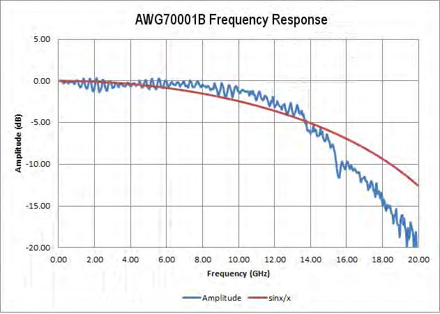
AWG70000B Series Arbitrary Waveform Generators

Analog output characteristics

Waveform characteristics
  Waveform file import capability   Import waveform format by series:
                                    .AWGX file created by Tektronix AWG5200/70000 Series

                                    .AWG file created by Tektronix AWG5000 or AWG7000 Series

                                    .PAT and *.WFM file formats created by Tektronix AWG400/500/600/700 Series

                                    .IQT file format created by Tektronix RSA3000 Series

                                    .TIQ file format created by Tektronix RSA6000/5000 Series or MDO4000 Series

                                    .WFM or *.ISF file formats created by Tektronix TDS/DPO/MSO/DSA Series

                                    .TXT file format

                                    .MAT Matlab file format

                                    .SEQX file format created by Tektronix AWG5200 Series

                                    .SEQ file format created by the Tektronix AWG400/500/600/700 Series

                                    .TMP or .PRM file formats; Midas Blue (Data Type 1000/1001; Scalar and complex data; 8-,16-, 32-, and 64-bit integer and 32-
                                    and 64-bit float data format types)

  Waveform file export capability
                                    .WFMX file format, AWG5200/70000 series native format
                                    .WFM file format, AWG400/500/600/700 waveform file
                                    .TIQ file format, RSA6000 IQ Pair
                                    .TXT file format

                                                                                                                                                 www.tek.com 9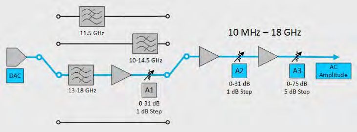
Datasheet

Trigger input characteristics
   Number                               2 (A and B)

   Connector                            SMA (rear panel)

   Polarity                             Positive or negative selectable

   Impedance                            50 Ω, 1 kΩ

   Range
       50 Ω
AWG70000B Series Arbitrary Waveform Generators
Spurious Free Dynamic Range (SFDR)
Spurious free dynamic range Frequency output of AWG 1 2
(SFDR) characteristics
AWG70001B operating at In band performance Adjacent band performance
50 GS/s
Analog channel output Measured across Specification Measured across Specification
frequency
100 MHz DC - 1 GHz -80 dBc DC - 10 GHz -72 dBc
DC - 500 MHz DC - 500 MHz -70 dBc DC - 1.5 GHz -66 dBc
DC - 1 GHz DC - 1 GHz -63 dBc DC - 3 GHz -63 dBc
DC - 2 GHz DC - 2 GHz -62 dBc DC - 6 GHz -60 dBc
DC - 3 GHz DC - 3 GHz -60 dBc DC - 6 GHz -52 dBc
DC - 5 GHz DC - 5 GHz -52 dBc DC - 6 GHz -52 dBc
5 GHz - 6 GHz 5 GHz - 6 GHz -52 dBc 3 GHz - 9 GHz -40 dBc
6 GHz - 7 GHz 6 GHz - 7 GHz -42 dBc 4 GHz - 10 GHz -42 dBc
7 GHz - 8 GHz 7 GHz - 8 GHz -60 dBc 6 GHz - 12.5 GHz -52 dBc
8 GHz - 10 GHz 8 GHz - 10 GHz -50 dBc 6 GHz - 12.5 GHz -52 dBc
10 GHz - 12 GHz 10 GHz - 12 GHz -53 dBc 6 GHz - 12.5 GHz -50 dBc
12 GHz - 13 GHz 12 GHz - 13 GHz -22 dBc 10 GHz - 15 GHz -22 dBc
13 GHz - 14 GHz 13 GHz - 14 GHz -54 dBc 11 GHz - 16 GHz -20 dBc
14 GHz - 16 GHz 14 GHz - 16 GHz -46 dBc 13 GHz - 18 GHz -38 dBc
16 GHz - 18.5 GHz 16 GHz - 18.5 GHz -42 dBc 14 GHz - 20 GHz -30 dBc
18.5 GHz - 20 GHz 18.5 GHz - 20 GHz -28 dBc 16 GHz - 20 GHz -24 dBc
AWG70001B and AWG70002B In band performance Adjacent band performance
operating at 25 GS/s
Analog channel output Measured across Specification Measured across Specification
frequency
100 MHz DC - 1 GHz -80 dBc DC - 10 GHz -72 dBc
0 - 500 MHz DC - 500 MHz -70 dBc DC - 1.5 GHz -66 dBc
DC - 1 GHz DC - 1 GHz -63 dBc DC - 3 GHz -63 dBc
DC - 2 GHz DC - 2 GHz -62 dBc DC - 6 GHz -60 dBc
DC - 3 GHz DC - 3 GHz -60 dBc DC - 6 GHz -52 dBc
DC - 5 GHz DC - 5 GHz -52 dBc DC - 6 GHz -52 dBc
5 GHz - 6 GHz 5 GHz - 6 GHz -52 dBc 3 GHz - 9 GHz -40 dBc
6 GHz - 7 GHz 6 GHz - 7 GHz -42 dBc 4 GHz - 10 GHz -42 dBc
7 GHz - 8 GHz 7 GHz - 8 GHz -55 dBc 6 GHz - 12.5 GHz -50 dBc
8 GHz - 10 GHz 8 GHz - 10 GHz -50 dBc 6 GHz - 12.5 GHz -50 dBc
1 Measured with Balun at maximum sample rate.
2 SFDR is determined as a function of the directly generated carrier frequency. Harmonics not included.
www.tek.com 11Datasheet
Output distortions
Harmonic distortion Sample rate = 25 GS/s
2nd harmonic, at output Frequency range Value
frequency
< 2 GHz < -60 dBc
2 GHz - 6 GHz < -50 dBc
> 6 GHz < -42 dBc
3rd harmonic, at output Frequency range Value
frequency
< 1 GHz < -60 dBc
1 GHz - 2 GHz < -50 dBc
> 2 GHz < -40 dBc
Effective number of bits (ENOB)
AWG70001B 4.6 bits at 14.99 GHz
All noise and distortion DC - 20 GHz
AWG70002B 5.6 bits at 9.99 GHz
All noise and distortion DC - 12.5 GHz
Phase noise Phase noise in reduced jitter mode.
Jitter
Random jitter 250 fs RMS
Total jitter 10 ps p-p at 12.5 Gb/s
12 www.tek.comAWG70000B Series Arbitrary Waveform Generators
Channel timing characteristics
These specifications apply to the AWG70002B only.
Channel to channel skew ±5 ps
Output skew control
Range -100 ps to 100 ps
Resolution 500 fs
Accuracy ±5 ps
Intra-channel skewDatasheet
Marker characteristics
Number
AWG70001B Total of 2
AWG70002B Total of 4 (2 per channel)
Style Differential
Connector SMA (front panel)
Impedance 50 Ω
Level into 50 Ω
Characteristic Value
Window -1.4 V to 1.4 V
Amplitude 0.5 V p-p to 1.4 V p-p
Resolution 10 mV
Accuracy ±(10% of setting + 50 mV) into 50 Ω
Rise/fall time (20% - 80%)AWG70000B Series Arbitrary Waveform Generators
Auxiliary Outputs
Auxiliary Outputs can be configured as sequencer flags or timers.
Connector SMB (rear panel)
Number of outputs
AWG70001B 4
AWG70002B 8
Impedance 50 Ω
Amplitude
High 3.3 V into 50 Ω
Low 0V
Period When configured as a timer.
1 Hz (1 s) to 100 kHz (10 μs)
Pattern jump
Pin assignments Pin Pin Pin
1 GND 6 GND 11 Data bit 5, input
2 Data bit 0, input 7 Strobe, input 12 Data bit 6, input
3 Data bit 1, input 8 GND 13 Data bit 7, input
4 Data bit 2, input 9 GND 14 GND
5 Data bit 3, input 10 Data bit 4, input 15 GND
Input impedance 1 kΩ pull-down to GND
Input levels 3.3 V LVCMOS
5 V TTL compliant
Number of destinations 256
Strobe polarity Negative edge
Strobe Minimum Pulse Width 64 ns
Strobe Setup and Hold
Setup 5 ns
Hold 5 ns
www.tek.com 15Datasheet
AWG70001B Option AC output characteristics
These characteristics apply to the optional AC output connector available with the AWG70001B models.
Connector Aeroflex/Weinschel Planar Crown Universal Connector System with SMA female adapter
Number of analog AC outputs 1
Type of outputs single ended
Output impedance 50 Ω
Frequency range Filter Value
No filter 10 MHz to 18 GHz
Low pass 10 MHz to 11.5 GHz
Band pass (10 to 14.5 GHz) 10 GHz to 14.5 GHz
Band pass (13 to 18 GHz) 14 GHz to 18 GHz
Amplitude
Range (for a CW signal at Filter Value
specified frequencies in each
No filter 25 dBm to -70 dBm at 1 GHz
path)
18 dBm to -77 dBm at 13 GHz
Low pass 25 dBm to -70 dBm at 1 GHz
Band pass (10 to 14.5 GHz) 18 dBm to -77 dBm at 11 GHz
Band pass (13 to 18 GHz) 20 dBm to -90 dBm at 14 GHz
18 dBm to -90 dBm at 18 GHz
Accuracy (at calibration Filter Value
frequency)
No filter ±0.5 dB at 1 GHz, ambient 16 °C to 26 °C
±1.5 dB at 1 GHz, ambient 0 °C to 50 °C
Low pass ±0.5 dB at 1 GHz, ambient 16 °C to 26 °C
±1.5 dB at 1 GHz, ambient 0 °C to 50 °C
Band pass (10 to 14.5 GHz) ±1.5 dB at 11 GHz, ambient 16 °C to 26 °C
±3.0 dB at 11 GHz, ambient 0 °C to 50 °C
Band pass (13 to 18 GHz) ±1.5 dB at 14 GHz, ambient 16 °C to 26 °C
±3.5 dB at 14 GHz, ambient 0 °C to 50 °C
Resolution 0.01 dB
Amplitude flatness Specifications include the sin(x)/x roll off of the DAC at 50 GS/s.
Filter Value
No filter ± 3 dB, 10 MHz to 10 GHz
± 4 dB, 10 MH to 13 GHz
Low pass ± 3 dB, 10 MHz to 10 GHz
Band pass (10 to 14.5 GHz) ± 3.5 dB, 10 GHz to 14.5 GHz
Band pass (13 to 18 GHz) ± 4.5 dB from 13 GHz to 18 GHz
16 www.tek.comAWG70000B Series Arbitrary Waveform Generators
AWG70001B Option AC output characteristics
Harmonic distortion Operating at 50 GS/s.
2nd Harmonic at output Frequency range Value
frequency
< 1 GHz < -34 dBc
1 GHz - 4 GHz < -30 dBc
> 4 GHz < -28 dBc
3rdHarmonic at output Frequency range Value
frequency
< 1 GHz < -50 dBc
1 GHz - 4 GHz < -45 dBc
> 4 GHz < -33 dBc
Amplifier 1 dB compression
Operating at 50 GS/s Filter Frequency Value
No filter 1 GHz > 25 dBm
13 GHz > 22 dBm
Low pass 1 GHz > 25 dBm
Band pass (10 to 14.5 GHz) 11 GHz > 22 dBm
Band pass (13 to 18 GHz) 14 GHz > 22 dBm
18 GHz > 20 dBm
Switching time The time required for the attenuators and amplifiers to settle to the specified output amplitude after an amplitude change.
20 ms
Power source
AC line input 100 to 240 V AC, 50/60 Hz
Consumption 500 Watts
www.tek.com 17Datasheet
Computer system
Operating system / peripherals / IO Microsoft Windows 10 operating system
16 GB
≥ 1 TB solid state drive
6 USB ports (2 front - USB 2.0 ) (4 rear - USB 3.0)
RJ-45 Ethernet connector (rear panel) supports 10/100/1000BASE-T
VGA video (rear panel) for external monitor
eSATA (rear panel)
Display characteristics LED backlit touch screen display, 132 x 99 mm (165 mm diagonal), 1024 × 768 pixels
Software driver for third-part IVI-COM driver
applications
IVI-C driver
Instrument control / data transfer
GPIB through USB B device Remote control and data transfer (conforms to IEEE-Std 488.1, compatible with IEEE-Std 488.2 and SCPI-1999.0)
port (requires external adapter
TEK-USB-488)
Ethernet Remote control and data transfer (conforms to IEEE-Std 802.3)
LAN eXtensions for Class LXI Class C Version 1.4
Instrumentation (LXI)
Physical characteristics
Dimensions
Height 153.6 mm (6.05 in)
Width 460.5 mm (18.13 in)
Depth 603 mm (23.76 in)
Weight
Net weight without packaging 37.0 lb (16.8 kg)
38.56 lb (17.49 kg) (AWG70001B with option AC)
Net weight with packaging 49.4 lb (22.4 kg)
50.96 lb (23.12 kg) (AWG70001B with option AC)
Cooling clearance
Top 0 in
Bottom 0 in
Left side 50 mm (2 in)
Right side 50 mm (2 in)
Rear 0 in
18 www.tek.comAWG70000B Series Arbitrary Waveform Generators
EMC, environment, and safety
Temperature
Operating 0 ºC to +50 ºC (+32 ºF to +122 ºF)
Non-operating -20 ºC to +60 ºC (-4 ºF to +140 ºF)
Humidity
Operating 5% to 90% relative humidity (% RH) at up to 30 °C
5% to 45% relative humidity above 30 °C up to 50 °C
Non-condensing
Non-operating 5% to 90% relative humidity (% RH) at up to 30 °C
5% to 45% relative humidity above 30 °C up to 60 °C
Non-condensing
Altitude
Operating Up to 3,000 meters (9,843 feet)
Derate maximum operating temperature by 1 °C per 300 meters above 1500 meters.
Non-operating Up to 12,000 meters (39,370 feet)
Vibration
Operating Sine: 0.33 mm p-p (0.013 in p-p) constant displacement, 5 to 55 Hz
Random: 0.27 GRMS from 5 to 500 Hz, 10 minutes per axis
Nonoperating Random: 2.28 GRMS from 5 to 500 Hz, 10 minutes per axis
Mechanical shock
Operating Half-sine mechanical shocks, 30 g peak, 11 ms duration, 3 drops in each direction of each axis
Regulatory
Safety UL61010-1, CAN/CSA-22.2, No.61010-1, EN61010-1, IEC61010-1
Emissions EN55011 (Class A), IEC61000-3-2, IEC61000-3-3
Immunity IEC61326, IEC61000-4-2/3/4/5/6/8/11
Regional certifications Europe Australia/New Zealand
EN61326 AS/NZS 2064
www.tek.com 19Datasheet
Ordering information
Models
AWG70001B 10 bit, 2 GSamples record length, 1-channel arbitrary waveform generator
AWG70000-150 50 Gs/s Sample Rate
AWG70000-MEM Waveform record length expansion to 32 G
AWG70001B AC Adds a single-ended AC coupled output connector with additional amplification and attenuation
AWG70001B SEQ Adds Sequencing
AWG70001B STRID Adds Streaming ID (requires AWG70001B SEQ)
AWG70002B 10 bit, 2 GSamples record length, 2-channel arbitrary waveform generator.
AWG70000-208 8 Gs/s Sample Rate
AWG70000-216 16 Gs/s Sample Rate
AWG70000-225 25 Gs/s Sample Rate
AWG70000-MEM Waveform record length expansion to 16 G per channel
AWG70002B SEQ Adds Sequencing
AWG70002B STRID Adds Streaming ID (requires AWG70002B SEQ)
Instrument options
Power plug options
Opt. A0 North America power plug (115 V, 60 Hz)
Opt. A1 Universal Euro power plug (220 V, 50 Hz)
Opt. A2 United Kingdom power plug (240 V, 50 Hz)
Opt. A3 Australia power plug (240 V, 50 Hz)
Opt. A4 North America power plug (240 V, 50 Hz)
Opt. A5 Switzerland power plug (220 V, 50 Hz)
Opt. A6 Japan power plug (100 V, 50/60 Hz)
Opt. A10 China power plug (50 Hz)
Opt. A11 India power plug (50 Hz)
Opt. A12 Brazil power plug (60 Hz)
Opt. A99 No power cord
Language options
Opt. L0 English manual
Opt. L5 Japanese manual
Opt. L7 Simplified Chinese manual
Opt. L8 Traditional Chinese manual
Opt. L10 Russian manual
Opt. L99 No manual
20 www.tek.comAWG70000B Series Arbitrary Waveform Generators
Service options
Opt. C3 Calibration Service 3 Years
Opt. C5 Calibration Service 5 Years
Opt. D1 Calibration Data Report
Opt. D3 Calibration Data Report 3 Years (with Opt. C3)
Opt. D5 Calibration Data Report 5 Years (with Opt. C5)
Opt. G3 Complete Care 3 Years (includes loaner, scheduled calibration, and more)
Opt. G5 Complete Care 5 Years (includes loaner, scheduled calibration, and more)
Opt. R3 Repair Service 3 Years (including warranty)
Opt. R5 Repair Service 5 Years (including warranty)
CA1 Single calibration or functional verification
R5DW Repair service coverage 5 years
R2PW Repair service coverage 2 years post warranty
R1PW Repair service coverage 1 year post warranty
www.tek.com 21Datasheet
Standard accessories
131-8689-xx Analog output Planar Crown 7005A-1 SMA female adapters (preinstalled)
AWG70001B: two (three with Option AC)
AWG70002B: four
015-1022-xx One 50 Ω SMA terminator per channel
119-7054-xx USB mouse
119-7275-xx Compact USB keyboard
— Installation and safety manual (Specify language option at time of order.)
— Certificate of calibration
— Power cord (Specify power cord option at time of order.)
Recommended accessories
Recommended accessories
Item Description Part number
Synchronization Hub Enables fast synchronization of multiple AWG70000 series AWGSYNC01 Synchronization Hub
instruments
GPIB to USB Adapter Enables GPIB control through USB B port TEK-USB-488
Rack mount kit Rack mount kit for AWG70000 Series AWGRACK
MDC4500-4B DC amplifier for MIPI applications MDC4500-4B
Baluns 200 kHz - 17 GHz Picosecond Pulse Labs 5315A
300 kHz - 26.5 GHz Marki BAL-0026
5 MHz - 20 GHz Hyperlabs HL9402
Bias Ts 10 kHz - 50 GHz Picosecond Pulse Labs 5542
200 kHz - 12 GHz Mini-Circuits ZX85-12G-S+
Power Splitters 1.5 kHz - 18 GHz Mini-Circuits ZX10-2-183-S+
DC-18 GHz Aeroflex/Weinschel 1515
Amplifiers 2.5 kHz - 10 GHz, 26 dB gain Picosecond Pulse Labs 5866
25 kHz - 45 GHz, 16 dB gain Picosecond Pulse Labs 5882
0.01 - 20 GHz, 30 dB gain RF-Lambda RAMP00G20GA
Adapter SMB female to SMA female Mouser 565-72979
Programmer manual Programming commands, English only 077-1452-xx (Visit the Tektronix website)
22 www.tek.comAWG70000B Series Arbitrary Waveform Generators
Product upgrades
The following instrument upgrades are available post sales.
See the Plug-ins section for a list of software waveform plug-ins available post sales.
AWG70001B
AWG701BUP AC Adds a single-ended AC coupled output connector with additional amplification and attenuation (factory upgrade only)
AWG701BUP SSD Replacement / additional Solid State Disc Drive
AWG701BUP MEM Increases waveform record length to 32 G
AWG701BUP SEQ Adds Sequencing
AWG701BUP STRID Adds Streaming ID
AWG70002B
AWG702BUP SSD Replacement / additional Solid State Disc Drive
AWG702BUP MEM Increases waveform record length to 16 G per channel
AWG702BUP 0816 Increases sampling rate from 8 GS/s to 16 GS/s
AWG702BUP 0825 Increases sampling rate from 8 GS/s to 25 GS/s
AWG702BUP 1625 Increases sampling rate from 16 GS/s to 25 GS/s
AWG702BU SEQ Adds Sequencing
AWG702BU STRID Adds Streaming ID
Plug-ins
Plug-ins increase the capabilities of the arbitrary waveform generators. Various plug-ins are available providing unique types of waveforms or additional compensation. Each
plug-in has its own installation file which installs seamlessly into the generators. After installation, it simply becomes a new menu selection. No other configuration is
necessary.
Plug-in Description Nomenclature Licensed enhancements
Multitone & Chirp plug-in Create chirps, notches, and tones MTONENL-SS01
MTONEFL-SS01
PreCompensation plug-in Create correction coefficients that can be PRECOMNL-SS01
applied on waveforms to get flat PRECOMFL-SS01
frequency and linear phase response
High Speed Serial plug-in Create pre-distorted waveforms to test a HSSNL-SS01 S-Parameters and Intersymbol
device's conformance to standards HSSFL-SS01 Interference unlocked with S-Parameters
HSSPACKNL-SS01 plug-in license
HSSPACKFL-SS01 Spread Spectrum Clocking unlocked with
Spread Spectrum Clocking plug-in
license
(Licensed enhancements are included
with HSSPACK)
RF Generic plug-in Create digitally modulated signals with RFGENNL-SS01 S-Parameters unlocked with S-
multiple carrier groups RFGENFL-SS01 Parameters plug-in license
Optical plug-in Create waveforms with complex OPTICALNL-SS01 S-Parameters unlocked with S-
modulation schemes for optical testing OPTICALFL-SS01 Parameters plug-in license
Spread Spectrum Clocking unlocked with
Spread Spectrum Clocking plug-in
license
OFDM plug-in Create Single or Multiple OFDM based OFDMNL-SS01 S-Parameters unlocked with S-
Frames with one or more bursts OFDMFL-SS01 Parameters plug-in license
www.tek.com 23Datasheet
Plug-in Description Nomenclature Licensed enhancements
RADAR plug-in Create RADAR pulsed waveforms with RADARNL-SS01 S-Parameters unlocked with S-
various modulations and impairments RADARFL-SS01 Parameters plug-in license
RADAR and Environment waveform RDRPACK1NL-SS01
creation plug-ins packaged together RDRPACK1FL-SS01
RADAR, Environment, and OFDM RDRPACK2NL-SS01
waveform creation plug-ins packaged RDRPACK2FL-SS01
together
Environment plug-in Create real world scenarios for ENVNL-SS01
commercial, electronic warfare, and ENVFL-SS01
simulations for monitoring and receiver
testing
Spread Spectrum Clocking plug-in Adds SSC capability to the High Speed SSCFLNL-SS01
Serial and Optical plug-ins SSCFLFL-SS01
S-Parameters plug-in Adds S-Parameter capability to the RF SPARANL-SS01
Generic, High Speed Serial, Optical, SPARAFL-SS01
OFDM, and RADAR plug-ins
Plug-ins require the purchase of a license before they are fully functional.
There are two types of licenses available for each plug-in: node-locked (NL) and floating (FL).
Node Locked Licenses (NL) provide your own copy of the application on your instrument and are permanently assigned to a product model/serial number.
Floating Licenses (FL) can be moved between product models.
Warranty
One-year parts and labor.
Tektronix is registered to ISO 9001 and ISO 14001 by SRI Quality System Registrar.
Product(s) complies with IEEE Standard 488.1-1987, RS-232-C, and with Tektronix Standard Codes and Formats.
24 www.tek.comAWG70000B Series Arbitrary Waveform Generators
www.tek.com 25Datasheet
ASEAN / Australasia (65) 6356 3900 Austria 00800 2255 4835* Balkans, Israel, South Africa and other ISE Countries +41 52 675 3777
Belgium 00800 2255 4835* Brazil +55 (11) 3759 7627 Canada 1 800 833 9200
Central East Europe and the Baltics +41 52 675 3777 Central Europe & Greece +41 52 675 3777 Denmark +45 80 88 1401
Finland +41 52 675 3777 France 00800 2255 4835* Germany 00800 2255 4835*
Hong Kong 400 820 5835 India 000 800 650 1835 Italy 00800 2255 4835*
Japan 81 (3) 6714 3086 Luxembourg +41 52 675 3777 Mexico, Central/South America & Caribbean 52 (55) 56 04 50 90
Middle East, Asia, and North Africa +41 52 675 3777 The Netherlands 00800 2255 4835* Norway 800 16098
People's Republic of China 400 820 5835 Poland +41 52 675 3777 Portugal 80 08 12370
Republic of Korea +822 6917 5084, 822 6917 5080 Russia & CIS +7 (495) 6647564 South Africa +41 52 675 3777
Spain 00800 2255 4835* Sweden 00800 2255 4835* Switzerland 00800 2255 4835*
Taiwan 886 (2) 2656 6688 United Kingdom & Ireland 00800 2255 4835* USA 1 800 833 9200
* European toll-free number. If not accessible, call: +41 52 675 3777
For Further Information. Tektronix maintains a comprehensive, constantly expanding collection of application notes, technical briefs and other resources to help engineers working on the cutting edge of technology. Please visit www.tek.com.
Copyright © Tektronix, Inc. All rights reserved. Tektronix products are covered by U.S. and foreign patents, issued and pending. Information in this publication supersedes that in all previously published material. Specification and
price change privileges reserved. TEKTRONIX and TEK are registered trademarks of Tektronix, Inc. All other trade names referenced are the service marks, trademarks, or registered trademarks of their respective companies.
15 Feb 2019 76W-61412-0
www.tek.com
For More Information: Vicom Australia Vicom New Zealand
1064 Centre Rd Grd Floor, 60 Grafton Road
Oakleigh South Vic Auckland 1010
3167 Australia 1300 New Zealand
360 251 +64 9 379 4596
info@vicom.com.au info@vicom.co.nz
www.vicom.com.au www.vicom.co.nzYou can also read